EP2228151A2 - Outil destiné à élargir une pièce usinée - Google Patents
Outil destiné à élargir une pièce usinée Download PDFInfo
- Publication number
- EP2228151A2 EP2228151A2 EP09177530A EP09177530A EP2228151A2 EP 2228151 A2 EP2228151 A2 EP 2228151A2 EP 09177530 A EP09177530 A EP 09177530A EP 09177530 A EP09177530 A EP 09177530A EP 2228151 A2 EP2228151 A2 EP 2228151A2
- Authority
- EP
- European Patent Office
- Prior art keywords
- tube
- pipe
- workpiece
- support portion
- deformation member
- Prior art date
- Legal status (The legal status is an assumption and is not a legal conclusion. Google has not performed a legal analysis and makes no representation as to the accuracy of the status listed.)
- Granted
Links
- 238000010438 heat treatment Methods 0.000 claims description 5
- 238000003754 machining Methods 0.000 description 15
- 238000003780 insertion Methods 0.000 description 14
- 230000037431 insertion Effects 0.000 description 14
- 238000005520 cutting process Methods 0.000 description 6
- 238000003825 pressing Methods 0.000 description 6
- 239000000463 material Substances 0.000 description 4
- 239000002131 composite material Substances 0.000 description 2
- 230000006835 compression Effects 0.000 description 2
- 238000007906 compression Methods 0.000 description 2
- 238000006073 displacement reaction Methods 0.000 description 2
- 239000002184 metal Substances 0.000 description 2
- 239000011324 bead Substances 0.000 description 1
- 230000005540 biological transmission Effects 0.000 description 1
- 239000013590 bulk material Substances 0.000 description 1
- 239000007788 liquid Substances 0.000 description 1
- 238000004519 manufacturing process Methods 0.000 description 1
- 210000003205 muscle Anatomy 0.000 description 1
- 239000011343 solid material Substances 0.000 description 1
- 125000006850 spacer group Chemical group 0.000 description 1
Images

Classifications
-
- B—PERFORMING OPERATIONS; TRANSPORTING
- B21—MECHANICAL METAL-WORKING WITHOUT ESSENTIALLY REMOVING MATERIAL; PUNCHING METAL
- B21D—WORKING OR PROCESSING OF SHEET METAL OR METAL TUBES, RODS OR PROFILES WITHOUT ESSENTIALLY REMOVING MATERIAL; PUNCHING METAL
- B21D41/00—Application of procedures in order to alter the diameter of tube ends
- B21D41/02—Enlarging
-
- B—PERFORMING OPERATIONS; TRANSPORTING
- B21—MECHANICAL METAL-WORKING WITHOUT ESSENTIALLY REMOVING MATERIAL; PUNCHING METAL
- B21D—WORKING OR PROCESSING OF SHEET METAL OR METAL TUBES, RODS OR PROFILES WITHOUT ESSENTIALLY REMOVING MATERIAL; PUNCHING METAL
- B21D17/00—Forming single grooves in sheet metal or tubular or hollow articles
- B21D17/02—Forming single grooves in sheet metal or tubular or hollow articles by pressing
-
- B—PERFORMING OPERATIONS; TRANSPORTING
- B21—MECHANICAL METAL-WORKING WITHOUT ESSENTIALLY REMOVING MATERIAL; PUNCHING METAL
- B21D—WORKING OR PROCESSING OF SHEET METAL OR METAL TUBES, RODS OR PROFILES WITHOUT ESSENTIALLY REMOVING MATERIAL; PUNCHING METAL
- B21D39/00—Application of procedures in order to connect objects or parts, e.g. coating with sheet metal otherwise than by plating; Tube expanders
- B21D39/08—Tube expanders
Definitions
- the present invention relates to an apparatus for processing a workpiece, in particular a pipe, with features according to the main claim.
- an O-ring whose outer diameter is greater than the inner diameter of the tube, not already pressed into the notch upon insertion into the tube, and a guided in the tube material (in particular a liquid and / or gas and / or Solid material, such as bulk material, can flow axially past the position of the O-ring, thereby ensuring that in the unpressed state there is always a leak in the connection between the fitting and the pipe to alert an installer in particular of a pressure drop during pressing For compression, the plastic deformation can then be radially outwardly deformed by applying a pressing tool to the tube outer wall, whereby the leakage produced by the notch and passing through the O-ring is produced by pressing the tube inner wall in the area of leakage to the OR ing canceled by plastic deformation of the pipe inner wall radially inward again.
- a guided in the tube material in particular a liquid and / or gas and / or Solid material, such as bulk material
- the DE 20 2008 005 983 U1 shows for this purpose a tool for expanding a workpiece with a round inner cross-section, in which a mandrel into one in the pipe inserted sleeve is introduced from one side of an open pipe end.
- the mandrel then presses on a jaw, which extends parallel to the tube longitudinal axis and then causes an at least partially deformation of the tube wall radially outward.
- the aim of the invention is therefore to provide a device for machining, in particular expansion, of workpieces, in particular pipes (ie metal pipes, plastic pipes and / or composite pipes) or workpieces which have at least rotational symmetry, which does not have any axial force during the machining of the pipe the open tube end exerts, through which the device according to the invention is introduced into the tube interior.
- pipes ie metal pipes, plastic pipes and / or composite pipes
- workpieces which have at least rotational symmetry, which does not have any axial force during the machining of the pipe the open tube end exerts, through which the device according to the invention is introduced into the tube interior.
- a radial direction is a direction perpendicular to the rotation axis of the support portion
- an axial direction is a direction parallel to the axis of symmetry of the support portion.
- the axis of symmetry of the support portion is parallel to an axis of rotational symmetry of the workpiece, in particular, the axis of symmetry of the support portion and the rotationally symmetric axis of the workpiece lie on each other.
- the axis of symmetry of the support section lies on the longitudinal axis of the device.
- the invention solves this problem by the subject of the main claim.
- the subclaims are directed to advantageous embodiments of the invention, wherein features of different embodiments can be combined.
- the apparatus for machining a workpiece in particular a tube, advantageously includes a deformation member for deforming a wall of the workpiece, a deflection portion which engages the deformation member and a support portion which is supported on a wall of the workpiece (advantageously an inner wall of a tube) and with is connected to the deflection section.
- machining of a workpiece is understood in particular to mean the deformation or change in the geometry of the workpiece, for example an at least regional radial expansion and / or round pressing and / or caking of a particular cylindrical and / or hollow cylindrical workpiece.
- the workpiece is in particular a tube, which may contain a metal and / or a plastic.
- the tube may therefore be a composite tube, for example.
- Further machining can also be understood as a deburring of the workpiece, ie, in the case of a pipe, in particular the removal of burrs at an open pipe end.
- the machining may further include calibrating a pipe, that is, in particular, adapting a wall thickness of the pipe jacket to a desired wall thickness, in particular at an open end of the pipe.
- the expansion of the tube means an enlargement of the tube diameter in at least one region of the tube wall (which is also referred to below as a partial expansion region), ie a deformation defined in its geometry and arrangement on the tube.
- the partial widening region is advantageously on the tube shell and in particular near an open end of the tube (which is also referred to below as the tube end).
- the deformation member is used for controlled deformation or deformation of a wall of the workpiece, ie in particular for partial expansion of a tube.
- a controlled deformation is to be understood as meaning, in particular, a deformation of the workpiece according to a fixed plan before the machining.
- the deformation member may be disposed on an outer surface or outer circumferential surface of an advantageously hollow cylindrical or advantageously at least rotationally symmetrical support section, wherein the cutout of the cylinder surface, on which the deformation member is arranged, during the deformation of a wall of the workpiece (in particular tube inner wall) is opposite.
- the cylinder axis of the support section is advantageously in the axial direction during machining.
- the support portion is inserted into the interior of the workpiece, for example, the support portion is then opposite in all directions of the pipe inner wall.
- the support portion is advantageously formed as a hollow cylinder and has arranged the deformation member on its outer circumferential surface.
- the support portion is arranged in its longitudinal direction within a support portion, wherein the longitudinal directions of support portion and support portion preferably lie parallel to each other.
- the hollow cylinder of the support portion thus has an outer diameter, which is advantageously smaller than the inner diameter of the support portion.
- the device according to the invention advantageously has a support section which is supported on a wall of the workpiece.
- the support portion is supported against a portion of a pipe inner wall (a support portion).
- the support region comprises at least one region which is diametrically opposed to the partial expansion region. But he can also rearrange this area, in particular be arranged around it.
- the support portion advantageously has a hollow cylindrical shape or at least a rotationally symmetrical shape and at least partially rearranges the support section.
- the support portion advantageously has an opening in its hollow cylinder shell through which the deformation member can pass to engage the workpiece.
- the hollow cylindrical support section advantageously has a cylinder axis which coincides with the axis of rotation of the deflection section or lies at least parallel thereto.
- the support portion exerts a counter force to the deformation force, wherein the deformation force is the force with which the deformation member deforms the workpiece.
- the support portion is advantageously at least partially inserted into a pipe opening and then abuts against the inner surface of the pipe (hereinafter also referred to as pipe inner surface).
- the device according to the invention advantageously includes a deflection section which moves the deformation member so that it engages the workpiece and can deform it.
- the deflection section is mounted rotatably relative to the support section in particular in the support section about an axis of rotation of the deflection section pointing in the longitudinal direction of the deflection section.
- the deflection portion is preferably cylindrical and / or hollow cylindrical and may be arranged with its part mounted in the support portion concentric with the support portion in this. In particular, the support portion in this part is therefore also cylindrical or hollow cylindrical.
- the outer diameter of the support portion is larger than the outer diameter of the Auslenkabitess in this case. If the support section is hollow-cylindrical, then the deflection section is preferably inserted into the interior of the hollow cylinder so that the longitudinal axes of the two sections are parallel to one another and in particular to one another.
- the deflection section can be driven by a control unit (in particular a motor or electric motor), for example by connection to a transmission, to rotate about its axis of rotation. This allows the machining of the workpiece without the need for an operator to spend his muscle power.
- the deflection section can also be manually driven by an operator to rotate about its axis of rotation.
- a manual drive device may be provided in particular at the open end of the deflection section lying outside the tube, which may for example take the form of a curve and / or a twist grip.
- the deflection section can be supported with a support region against the support section, so that the deformation force of the deformation element transmitted via the support section to the deflection section can be transmitted via the support section to a region of the inner wall of the pipe which is diametrically opposite to the partial expansion area.
- Deformation force is understood in this context to be, in particular, that force with which the deformation member deforms the workpiece.
- the support section can in particular have a greater wall thickness of its hollow cylinder than in its region introduced into the tube interior.
- the axis of rotation of the Auslenkabitess can coincide with the cylinder axis of a hollow cylindrical support portion or at least parallel to this.
- the deflection section comprises an eccentric, which in particular has a cylindrical and / or hollow cylindrical or at least rotationally symmetrical shape.
- This eccentric may have the shape of a shaft which has a surface in a specific part, in which eccentricity is to be effected, whose distance from the axis of rotation of the advantageously hollow-cylindrical deflection section is greater than the distance of a surface region of the shaft diametrically opposite this surface region.
- the longitudinal axis of the shaft, in the region in which the eccentric is arranged on it, not on the axis of rotation about which rotates the shaft; the two But axes are advantageously parallel to each other.
- the support section can move relative to the tube, in particular rotate about an axis of rotation which lies parallel to the tube longitudinal axis and slide along the tube inner surface.
- the shaft is rotatably mounted with the eccentric relative to the support portion, so that the deformation member can be moved radially outwardly through the opening of the support portion to engage the pipe inner wall.
- the support portion are rotated relative to the pipe wall, the eccentric are further rotated and the deformation member are applied at a different processing location than the aforementioned again to the pipe inner wall.
- the support section has at least one, advantageously two, calibrating sections which, in particular, run around the support section (ie, around the entire circumference of the support section) in the form of annular bulges and are advantageously integrally formed integrally with the support section.
- a Kalibrierabêt is interrupted or has a gap along its circumference when it hits in its course on the opening of the support portion through which the deformation member can be moved. The gap in the calibration section then coincides with the opening of the support section.
- the calibration sections advantageously form the only components of the support section which abut against the tube inner wall.
- the term inner wall of the pipe in particular does not refer to the edges of the pipe jacket at an open pipe end, but rather to the inner surface of the pipe (which is particularly close to the end of the pipe).
- the purpose of the calibration sections is to use the To calibrate geometry of the workpiece, in particular the tube shell or an end portion of the tube.
- the calibration sections serve to adapt its geometry to a desired geometry or to obtain its desired geometry during machining during the machining of the tube.
- the desired geometry may in particular be a nominal diameter of a pipe.
- the calibration sections are advantageously positively and / or precisely fitting to the inner wall of the pipe and exert a force on the inner circumference of the pipe (in particular in the area of its contact surface) on the inner wall, so that a selective pressure force of the deformation element does not affect the partial expansion area leads to a particular oval deformation of the tubular jacket in a region which is greater than the partial expansion area.
- the device according to the invention includes a deburrer for deburring an end portion of the workpiece.
- the deburrer can be formed or formed on the support portion and is advantageously during the machining of the workpiece outside of the workpiece, in particular outside the tube shell.
- the deburrer may be formed as a projecting portion of the support portion which engages the base of the tube shell and / or the edges of the tube shell at the open tube end through which the device according to the invention, in particular the deformation member is introduced into the tube or has been ,
- This protruding portion advantageously rearranges the said areas of the tubular jacket or lies opposite them.
- the deburrer advantageously has a diameter which is greater than the outer diameter of the tube, that is to say may preferably comprise the tube circumference at the tube end or may rest against it.
- the deburrer may be formed around the full circumference of the support portion or may be provided only in a sector on the circumference of the support portion.
- the deburrer can advantageously separate at a point which bears against an inner edge of the tubular jacket, a cutting section and / or a chip removal section or planer for removing burrs, which have arisen, for example, during the manufacture of the pipe to be machined from a longer pipe to cut off.
- This cutting section or Abspanabites can be designed, for example in the form of blades that separate the ridges.
- the Abspanabites to a larger diameter than the hollow cylindrical portion of the support portion, in particular, the Abspanabites has a diameter which is greater than the diameter of the annular Kalibrierabitese.
- the Abspanabites is thus also advantageously fully arranged around a portion of the support portion.
- the cutting section or Abspanabites include a groove into which the jacket of the open pipe end is inserted to oppose the deburring pressure on the inner edge of the pipe jacket a back pressure, or clamp the pipe jacket. The radially outer region of such a groove thus acts as a counterpart to the Abspanabites or cutting section. This is to prevent that during deburring the last portion of the tube shell is pressed in front of the open end radially outward beyond its nominal diameter.
- a bearing is arranged between the eccentric and the deformation member.
- the bearing is located between the eccentric and the support section.
- This bearing can be a tapered roller bearing or a ball bearing.
- a bearing runs in a space between the eccentric and support section, in particular along the entire inner circumference of a hollow cylindrical support section. This makes it possible for the eccentric to move relative to the deformation member, in particular to be able to rotate relative to it. Rotation of the eccentric with the eccentricity in a direction away from the position of the deformation member then causes the deformation member to move in an inward radial direction (ie, pull in) of the deformation member through the opening of the support portion.
- a rotation of the eccentric with the greater eccentricity in the direction of the deformation member then causes a displacement of the deformation member in a radial outward direction (ie a push-out) through the opening of the support portion.
- the deformation member is pressed against this inner wall and can deform the inner wall by the force exerted therewith, in particular radially expand to the outside and thus at least partially increase the pipe diameter (especially in the partial expansion area).
- the support portion thus advantageously has an opening through which the deformation member can be moved, in particular retracted and extended.
- a retraction is understood in the context of this invention that the deformation member is moved radially inwardly relative to the radius of the advantageously hollow cylindrical support portion.
- a movement in the opposite direction ie in particular radially outward relative to the support section.
- the movement is translational, i. in a linear direction along a radius of the support portion.
- the support section is not arranged rotatably relative to the support section.
- the support portion can then not rotate relative to the support portion, since at any time the deformation member is at least partially in the opening of the support portion and thus prevents rotation of the support portion relative to the support portion.
- the deformation member at least partially moves out of the opening radially outward, i. is at least partially more outer relative to the radius of the support portion than the outer periphery of the support portion when it is extended through the opening.
- the deformation member is formed linearly in the form of an elevation on the support portion, thus having a longitudinal axis parallel to the axis of rotation of the eccentric extension, which is greater than the transverse extent of the deformation member, wherein the direction of the transverse extension in particular perpendicular to the direction of the axis of rotation of the eccentric.
- the opening of the support portion, through which the deformation member can be moved advantageously has a geometry which allows a passage of the deformation member. In this respect, it is advantageous if the opening has a similar to the geometry of the deformation member linear configuration.
- the surface of the deformation member which faces during processing of the pipe inner wall or is applied to this, is advantageously rounded.
- This rounding may have a larger, equal or smaller curvature than the tube inner wall. This prevents a square widening area, which is angular in its base area, from being forced out of the tube wall, which could lead to greater mechanical stresses and possibly a breakage of the tube wall.
- the deformation member has a length in the axial direction, with which a deformation in the pipe inner wall, for example in the form of a notch can be formed so that the longitudinal extent of this deformation at least one, advantageously two O-rings opposite, between the pipe inner wall and a in the Pipe inserted fitting or connecting part are arranged. This ensures that in the unpressed state there is a leak in the connection between the fitting and the pipe so that material carried in the pipe can flow past the position of the O-rings.
- the length of the deformation member in the axial direction is dimensioned so that it is at least as large as the distance between the non-axially opposite each other and in particular pointing in different axial directions surfaces of two O-rings, which are arranged on a pipe to be inserted into the fitting.
- the deformation member can also be designed to advantageously form a marking notch in a front-side end of the workpiece, in particular of a tube into which the device according to the invention is inserted, during the course of or during the machining.
- the deformation member may also have a length in the axial direction, so that it is opposite to an end portion of the pipe wall (ie in particular an end portion of the pipe inner wall at the open end of the pipe through which the device according to the invention is introduced).
- This can during processing a permanent (advantageous plastic) deformation, in particular a radially outwardly protruding from the pipe wall notch (which is also referred to as a notch hereinafter) are formed in this end region of the pipe wall, in particular pressed.
- This notch is advantageously arranged to lie between the pipe end and an O-ring of a fitting inserted into the pipe, the O-ring being the closest to the pipe end in the axial direction attached to the fitting O-ring. But it may in particular extend in the axial direction to the open end of the tube and in the open-lying circumference of the tubular jacket (ie in particular frontally at the tube end) to be formed.
- the deformation member may also include a marking area, which protrudes further outwardly, in particular in the radial direction during machining than axially further away from the pipe end portions of the deformation member and / or a cutting device or separating device includes.
- this identification area can be a marking notch in the form of a recess (ie one example in the axial direction extending material-free area in the pipe wall) are formed or cut in the pipe wall.
- the marking notch advantageously serves to make an installer recognize, even after pressing the pipe with a fitting, that a deformation has been formed to create a leak prior to compression into the pipe. Finally, this deformation was plastically deformed back into the tube wall by the pressing, so that the tube can not visually recognize externally under certain circumstances, whether it has been processed or not.
- the device according to the invention may include a heating device for heating the deformation member.
- the deformation member can be heated to heat the material of the tube at least within the partial expansion range, to facilitate a deformation, in particular a plastic deformation.
- This can be applied to the deformation member, for example, an electrical resistance heating, which heats at least the attacking on the pipe inner surface of the deformation member to the temperature, which increases depending on the material of the pipe wall, the deformability of the pipe wall, for example, with respect to their deformability at room temperature.
- Part of the invention is also a system of an apparatus described above for processing a workpiece and a workpiece, in particular a pipe.
- the device described above may be introduced into the tube to allow processing, but the device and the tube may also be present separately from one another in the system.
- FIG. 1 shows a cross section through an inserted into a pipe device according to the invention.
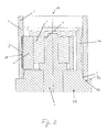
- FIG. 2 shows a longitudinal section through the device according to the invention when it is inserted into a tube.
- FIG. 1 shows a cross section through an inserted into a pipe device according to the invention, wherein the cross section intersects the deformation member 10 perpendicular to its axial extent.
- the device comprises a hollow cylindrical support section 1 with an opening in the form of a slot 13, through which a web 3 fixed to a hollow cylindrical support section 2 can be moved with a deformation member 10.
- the slot interrupts the circumference of the support portion 1 and runs in its longitudinal extent parallel to the longitudinal axis 14 of the support portion 1.
- a shaft 5 is used with an eccentric 6, whose longitudinal axis is spaced by a distance d from the longitudinal axis of the hollow cylindrical support portion 1.
- the longitudinal axis of the support section 1 advantageously comprises the axis of rotation of the shaft 5 and of the eccentric 6.
- the distance d is equal to the maximum elevation of the semi-circular deformation section 10 radially outward relative to the outer periphery of the support section 1.
- a camp 4 fully formed. So the camp has advantageous also hollow cylinder shape.
- the bearing 4 is radially outwardly adjacent to the inner surface of the hollow cylindrical support portion 2.
- the bearing 4 is also arranged rotatable about a longitudinal direction of the device according to the invention relative to the support portion 2. In FIG.
- the device according to the invention is introduced into a tube 7, wherein it can be seen that the deformation portion 10 presses into the inner wall of the tube 7.
- the processing according to the invention in particular deformation of the tubular jacket (at least on its inner side) becomes possible.
- FIG. 2 shows a longitudinal section through the device according to the invention, when it is inserted into a tube 7.
- the cut lies in a radial longitudinal plane of the web 3, on which the deformation member 10 is arranged.
- the support section 1 an insertion section 1a, which is inserted into the interior of the tube and in particular the inner surface of the tube 7 opposite, and a base portion 1b, which is located outside the tube opening and in particular integrally with the deburrer 9, its groove 9b and the outer part 9a of the groove 9b is formed comprises.
- a shaft 5 is coaxially mounted, which projects into a hollow cylindrical interior of the insertion section 1 a and has an eccentric 6.
- the longitudinal axis of the shaft 5 is spaced by a distance d from the axis of rotation of the shaft 5.
- the shaft 5 is not rotationally symmetrical to the axis of rotation 11.
- the support portion 1 is advantageously divided into two areas, wherein the base portion 1b is formed as a hollow cylinder with a thicker wall thickness than the insertion portion 1a.
- a wall portion of the base portion 1b is axially opposed to the free inner volume of the insertion portion 1a; the insertion section 1a is thus advantageously arranged on a radially outer wall region of the base section 1b.
- the insertion section 1a does not touch the inner wall of the tube 7, but has two calibrating sections 8, which for example advantageously run completely along the outer wall of the insertion section 1a as a bead or annular elevations.
- These calibration sections 8 space the outer surface of the insertion section 1a by the amount of its bead-shaped elevation over this outer surface of the inner wall of the tube 7.
- the deburrer 9 (which here comprises, for example, a rubbing surface, in particular a planer and / or a file) at least one inner surface Touched edge of the pipe end.
- the deburrer 9 comprises, for example, a rubbing surface, in particular a planer and / or a file
- the deburrer 9 By a particular rotating movement of the Entgraters 9 relative to the jacket of the tube 7 can thus be removed, in particular cutting or filing of burrs on the inner edge.
- This relative movement can take place in particular in that the support section 1 or at least the base section 1b (when this is formed rotatably about the longitudinal axis 14 relative to the insertion section 1a) take place.
- the groove 9b is adapted to receive the wall thickness of the tube 7 and thus to provide by the outer region 9a for a counter pressure during deburring.
- the calibration sections 8 take on the function of supporting sections of the support section 1 against the inner wall of the tube 7, so that a counter-pressure is created against the deformation force exerted by the deformation member 10 on the wall of the tube 7.
- the calibration sections 8 are also shown bead-like in cross-section, in order to facilitate insertion into the interior of a hollow cylindrical tube or along the inner edge of the tube end or to simplify.
- the stroke that is to say the maximum change (in particular reduction) of the distance of the longitudinal axis 12 of the eccentric 6 from the axis of rotation 11 of the shaft 5, can be limited at least in a direction of movement of the deformation member 10 pointing radially inward.
- a spacing part for example in the form of a bead-shaped or web-shaped elevation, which advantageously extends parallel to the longitudinal axis of the hollow cylindrical support section 2
- a corresponding spacer part can also be provided at the opposite point of the hollow cylindrical inner surface of the support section 1, in particular of the insertion section 1a.
- the web 13 is designed so that it can be released from the tube 7 without self-locking, when the deformation member 10 just engages in the inner surface of the tube 7.
- the outer region 9a of the groove 9b can also take over the function of the deburrer 9 for removing burrs on the outer edge of the pipe wall at the pipe opening.
- the outer region 9 a represents an outer deburrer, which may have features such as the deburrer 9. In particular, it can be constructed in the same way as the deburrer 9.
- the calibration sections 8 preferably have an outer diameter, which rests snugly on the inner wall of a tube having a pipe outer diameter of in particular 32 mm. It is also possible to construct the calibration sections 8 such that their outer diameter can rest against tubes having a different outer pipe diameter, in particular less than 32 mm or more than 32 mm.
- the base portion 1b advantageously serves as a handle for manual operation of the device according to the invention.
- the basic section 1b can have a double function as handle and carrier of the deburrer 9.
- a manual operation in particular a manual rotation of the base portion 1b for deburring and / or the shaft 5 for moving the eccentric 6 and thus the deformation member 10 is provided, in particular on the outside of the tube 7 located end of the shaft 5 may be arranged a rotating device, for example, take the form of a crank or a rotary handle.
Landscapes
- Engineering & Computer Science (AREA)
- Mechanical Engineering (AREA)
- Jigs For Machine Tools (AREA)
- Shaping Metal By Deep-Drawing, Or The Like (AREA)
- Shaping Of Tube Ends By Bending Or Straightening (AREA)
Applications Claiming Priority (1)
| Application Number | Priority Date | Filing Date | Title |
|---|---|---|---|
| DE202009003387 | 2009-03-09 |
Publications (3)
| Publication Number | Publication Date |
|---|---|
| EP2228151A2 true EP2228151A2 (fr) | 2010-09-15 |
| EP2228151A3 EP2228151A3 (fr) | 2014-01-01 |
| EP2228151B1 EP2228151B1 (fr) | 2015-05-13 |
Family
ID=42315694
Family Applications (1)
| Application Number | Title | Priority Date | Filing Date |
|---|---|---|---|
| EP20090177530 Not-in-force EP2228151B1 (fr) | 2009-03-09 | 2009-11-30 | Outil destiné à élargir une pièce usinée |
Country Status (1)
| Country | Link |
|---|---|
| EP (1) | EP2228151B1 (fr) |
Cited By (4)
| Publication number | Priority date | Publication date | Assignee | Title |
|---|---|---|---|---|
| CN107737846A (zh) * | 2017-11-14 | 2018-02-27 | 范科晨 | 带双驱动结构的铜管胀管器 |
| CN107876643A (zh) * | 2017-11-14 | 2018-04-06 | 范科晨 | 双向铜管胀管器 |
| CN107900240A (zh) * | 2017-11-14 | 2018-04-13 | 范科晨 | 带棘爪结构的行星式胀管装置 |
| CN116117012A (zh) * | 2023-04-13 | 2023-05-16 | 德州黄河建业工程有限责任公司维修养护分公司 | 一种用于水利工程管道扩口的冲压设备以及方法 |
Citations (1)
| Publication number | Priority date | Publication date | Assignee | Title |
|---|---|---|---|---|
| DE202008005983U1 (de) | 2008-04-30 | 2008-07-31 | Ipa Produktions- Und Vertriebsges.M.B.H. | Werkzeug zum Aufweiten eines Werkstücks |
Family Cites Families (3)
| Publication number | Priority date | Publication date | Assignee | Title |
|---|---|---|---|---|
| FR1352265A (fr) * | 1963-01-03 | 1964-02-14 | Machine à onduler les viroles de fûts métalliques | |
| JP3846643B2 (ja) * | 1996-01-29 | 2006-11-15 | 株式会社ショーワ | ガスシリンダ装置のシリンダ溝加工装置及び加工方法 |
| DE10325979B4 (de) * | 2003-06-07 | 2005-05-12 | Daimlerchrysler Ag | Spreizwerkzeug |
-
2009
- 2009-11-30 EP EP20090177530 patent/EP2228151B1/fr not_active Not-in-force
Patent Citations (1)
| Publication number | Priority date | Publication date | Assignee | Title |
|---|---|---|---|---|
| DE202008005983U1 (de) | 2008-04-30 | 2008-07-31 | Ipa Produktions- Und Vertriebsges.M.B.H. | Werkzeug zum Aufweiten eines Werkstücks |
Cited By (4)
| Publication number | Priority date | Publication date | Assignee | Title |
|---|---|---|---|---|
| CN107737846A (zh) * | 2017-11-14 | 2018-02-27 | 范科晨 | 带双驱动结构的铜管胀管器 |
| CN107876643A (zh) * | 2017-11-14 | 2018-04-06 | 范科晨 | 双向铜管胀管器 |
| CN107900240A (zh) * | 2017-11-14 | 2018-04-13 | 范科晨 | 带棘爪结构的行星式胀管装置 |
| CN116117012A (zh) * | 2023-04-13 | 2023-05-16 | 德州黄河建业工程有限责任公司维修养护分公司 | 一种用于水利工程管道扩口的冲压设备以及方法 |
Also Published As
| Publication number | Publication date |
|---|---|
| EP2228151B1 (fr) | 2015-05-13 |
| EP2228151A3 (fr) | 2014-01-01 |
Similar Documents
| Publication | Publication Date | Title |
|---|---|---|
| EP2918375B1 (fr) | Mordache, procédé de fabrication d'un raccord tubulaire fixe, raccord et système comprenant une mordache et un raccord | |
| DE10392402T5 (de) | Umlaufende, mit Rollen versehene Rillenbildungseinrichtung für ein Rohr | |
| EP2228151B1 (fr) | Outil destiné à élargir une pièce usinée | |
| WO2013030102A1 (fr) | Appareil de montage préalable de bague coupante pour raccords filetés pour tube | |
| DE4410146C2 (de) | Vorrichtung zur Herstellung von Pressfittings | |
| DE102011008068A1 (de) | Vorrichtung und Verfahren zur Herstellung von Tubenrohren für Verpackungstuben | |
| WO2011113954A1 (fr) | Procédé et dispositif de fabrication de bagues profilées | |
| EP1186820B1 (fr) | Dispositif pour réaliser une liaison permanente entre l'extrémité d'un tuyau et un raccord | |
| DE2651889C3 (de) | Einziehwerkzeug | |
| DE2851944A1 (de) | Vorrichtung zur herstellung von rohrkoerpern mit axial aufeinanderfolgenden querwellen | |
| EP2882556B1 (fr) | Agencement d'outil avec dispositif de centrage | |
| EP3315231B1 (fr) | Ouitl d'usinage d'extrémité de tube | |
| WO2017036610A1 (fr) | Tête d'étanchéité, dispositif et procédé de production de tubes bimétalliques | |
| EP3034190B1 (fr) | Procede de preparation d'un corps tubulaire rainure d'un echangeur de chaleur et bobine de tuyau rainure | |
| DE4336261C2 (de) | Verfahren zum Herstellen von Pressfittings und Vorrichtung zur Durchführung des Verfahrens | |
| EP2446980A2 (fr) | Tuyau et procédé destinés au traitement d'extrémités de tuyaux | |
| DE102008061442A1 (de) | Multidimensions-Rohraufweitvorrichtung | |
| DE102014112754A1 (de) | Stauchverfahren und Stauchvorrichtung | |
| DE930252C (de) | Rohrkupplung | |
| WO2012107031A1 (fr) | Dispositif de bordage d'extrémités de tuyaux | |
| EP3427897A1 (fr) | Dispositif d'usinage de tubes et d'autres corps ronds | |
| DE102017128474B3 (de) | Rohrschneidemaschine mit Schneiddorn | |
| WO2015117781A1 (fr) | Ensemble cylindre-piston muni d'un élément rapporté | |
| CH703639A1 (de) | Verfahren zur Umformung eines vorlaufenden Endabschnitts eines Stangenmaterials. | |
| DE10026461A1 (de) | Vorrichtung zum Bearbeiten eines Endabschnitts einer röhrenartigen Leitung, insbesondere Schneidwerkzeug für Schlauchenden |
Legal Events
| Date | Code | Title | Description |
|---|---|---|---|
| PUAI | Public reference made under article 153(3) epc to a published international application that has entered the european phase |
Free format text: ORIGINAL CODE: 0009012 |
|
| AK | Designated contracting states |
Kind code of ref document: A2 Designated state(s): AT BE BG CH CY CZ DE DK EE ES FI FR GB GR HR HU IE IS IT LI LT LU LV MC MK MT NL NO PL PT RO SE SI SK SM TR |
|
| PUAL | Search report despatched |
Free format text: ORIGINAL CODE: 0009013 |
|
| AK | Designated contracting states |
Kind code of ref document: A3 Designated state(s): AT BE BG CH CY CZ DE DK EE ES FI FR GB GR HR HU IE IS IT LI LT LU LV MC MK MT NL NO PL PT RO SE SI SK SM TR |
|
| RIC1 | Information provided on ipc code assigned before grant |
Ipc: B21D 17/02 20060101ALI20131128BHEP Ipc: B21D 41/02 20060101AFI20131128BHEP Ipc: B21D 39/08 20060101ALI20131128BHEP |
|
| 17P | Request for examination filed |
Effective date: 20140626 |
|
| RBV | Designated contracting states (corrected) |
Designated state(s): AT BE BG CH CY CZ DE DK EE ES FI FR GB GR HR HU IE IS IT LI LT LU LV MC MK MT NL NO PL PT RO SE SI SK SM TR |
|
| GRAP | Despatch of communication of intention to grant a patent |
Free format text: ORIGINAL CODE: EPIDOSNIGR1 |
|
| RIC1 | Information provided on ipc code assigned before grant |
Ipc: B21D 17/02 20060101ALI20141222BHEP Ipc: B21D 39/08 20060101ALI20141222BHEP Ipc: B21D 41/02 20060101AFI20141222BHEP |
|
| INTG | Intention to grant announced |
Effective date: 20150120 |
|
| GRAS | Grant fee paid |
Free format text: ORIGINAL CODE: EPIDOSNIGR3 |
|
| GRAA | (expected) grant |
Free format text: ORIGINAL CODE: 0009210 |
|
| AK | Designated contracting states |
Kind code of ref document: B1 Designated state(s): AT BE BG CH CY CZ DE DK EE ES FI FR GB GR HR HU IE IS IT LI LT LU LV MC MK MT NL NO PL PT RO SE SI SK SM TR |
|
| REG | Reference to a national code |
Ref country code: GB Ref legal event code: FG4D Free format text: NOT ENGLISH |
|
| REG | Reference to a national code |
Ref country code: CH Ref legal event code: EP |
|
| REG | Reference to a national code |
Ref country code: IE Ref legal event code: FG4D Free format text: LANGUAGE OF EP DOCUMENT: GERMAN |
|
| REG | Reference to a national code |
Ref country code: AT Ref legal event code: REF Ref document number: 726631 Country of ref document: AT Kind code of ref document: T Effective date: 20150615 |
|
| REG | Reference to a national code |
Ref country code: DE Ref legal event code: R096 Ref document number: 502009011024 Country of ref document: DE Effective date: 20150625 |
|
| REG | Reference to a national code |
Ref country code: NL Ref legal event code: MP Effective date: 20150513 |
|
| REG | Reference to a national code |
Ref country code: LT Ref legal event code: MG4D |
|
| PG25 | Lapsed in a contracting state [announced via postgrant information from national office to epo] |
Ref country code: PT Free format text: LAPSE BECAUSE OF FAILURE TO SUBMIT A TRANSLATION OF THE DESCRIPTION OR TO PAY THE FEE WITHIN THE PRESCRIBED TIME-LIMIT Effective date: 20150914 Ref country code: FI Free format text: LAPSE BECAUSE OF FAILURE TO SUBMIT A TRANSLATION OF THE DESCRIPTION OR TO PAY THE FEE WITHIN THE PRESCRIBED TIME-LIMIT Effective date: 20150513 Ref country code: HR Free format text: LAPSE BECAUSE OF FAILURE TO SUBMIT A TRANSLATION OF THE DESCRIPTION OR TO PAY THE FEE WITHIN THE PRESCRIBED TIME-LIMIT Effective date: 20150513 Ref country code: NO Free format text: LAPSE BECAUSE OF FAILURE TO SUBMIT A TRANSLATION OF THE DESCRIPTION OR TO PAY THE FEE WITHIN THE PRESCRIBED TIME-LIMIT Effective date: 20150813 Ref country code: ES Free format text: LAPSE BECAUSE OF FAILURE TO SUBMIT A TRANSLATION OF THE DESCRIPTION OR TO PAY THE FEE WITHIN THE PRESCRIBED TIME-LIMIT Effective date: 20150513 Ref country code: LT Free format text: LAPSE BECAUSE OF FAILURE TO SUBMIT A TRANSLATION OF THE DESCRIPTION OR TO PAY THE FEE WITHIN THE PRESCRIBED TIME-LIMIT Effective date: 20150513 |
|
| PG25 | Lapsed in a contracting state [announced via postgrant information from national office to epo] |
Ref country code: IS Free format text: LAPSE BECAUSE OF FAILURE TO SUBMIT A TRANSLATION OF THE DESCRIPTION OR TO PAY THE FEE WITHIN THE PRESCRIBED TIME-LIMIT Effective date: 20150913 Ref country code: GR Free format text: LAPSE BECAUSE OF FAILURE TO SUBMIT A TRANSLATION OF THE DESCRIPTION OR TO PAY THE FEE WITHIN THE PRESCRIBED TIME-LIMIT Effective date: 20150814 Ref country code: LV Free format text: LAPSE BECAUSE OF FAILURE TO SUBMIT A TRANSLATION OF THE DESCRIPTION OR TO PAY THE FEE WITHIN THE PRESCRIBED TIME-LIMIT Effective date: 20150513 Ref country code: BG Free format text: LAPSE BECAUSE OF FAILURE TO SUBMIT A TRANSLATION OF THE DESCRIPTION OR TO PAY THE FEE WITHIN THE PRESCRIBED TIME-LIMIT Effective date: 20150813 |
|
| PG25 | Lapsed in a contracting state [announced via postgrant information from national office to epo] |
Ref country code: EE Free format text: LAPSE BECAUSE OF FAILURE TO SUBMIT A TRANSLATION OF THE DESCRIPTION OR TO PAY THE FEE WITHIN THE PRESCRIBED TIME-LIMIT Effective date: 20150513 Ref country code: DK Free format text: LAPSE BECAUSE OF FAILURE TO SUBMIT A TRANSLATION OF THE DESCRIPTION OR TO PAY THE FEE WITHIN THE PRESCRIBED TIME-LIMIT Effective date: 20150513 |
|
| REG | Reference to a national code |
Ref country code: DE Ref legal event code: R097 Ref document number: 502009011024 Country of ref document: DE |
|
| PG25 | Lapsed in a contracting state [announced via postgrant information from national office to epo] |
Ref country code: PL Free format text: LAPSE BECAUSE OF FAILURE TO SUBMIT A TRANSLATION OF THE DESCRIPTION OR TO PAY THE FEE WITHIN THE PRESCRIBED TIME-LIMIT Effective date: 20150513 Ref country code: RO Free format text: LAPSE BECAUSE OF NON-PAYMENT OF DUE FEES Effective date: 20150513 Ref country code: CZ Free format text: LAPSE BECAUSE OF FAILURE TO SUBMIT A TRANSLATION OF THE DESCRIPTION OR TO PAY THE FEE WITHIN THE PRESCRIBED TIME-LIMIT Effective date: 20150513 Ref country code: SK Free format text: LAPSE BECAUSE OF FAILURE TO SUBMIT A TRANSLATION OF THE DESCRIPTION OR TO PAY THE FEE WITHIN THE PRESCRIBED TIME-LIMIT Effective date: 20150513 |
|
| PLBE | No opposition filed within time limit |
Free format text: ORIGINAL CODE: 0009261 |
|
| STAA | Information on the status of an ep patent application or granted ep patent |
Free format text: STATUS: NO OPPOSITION FILED WITHIN TIME LIMIT |
|
| 26N | No opposition filed |
Effective date: 20160216 |
|
| PG25 | Lapsed in a contracting state [announced via postgrant information from national office to epo] |
Ref country code: IT Free format text: LAPSE BECAUSE OF FAILURE TO SUBMIT A TRANSLATION OF THE DESCRIPTION OR TO PAY THE FEE WITHIN THE PRESCRIBED TIME-LIMIT Effective date: 20150513 |
|
| PG25 | Lapsed in a contracting state [announced via postgrant information from national office to epo] |
Ref country code: SI Free format text: LAPSE BECAUSE OF FAILURE TO SUBMIT A TRANSLATION OF THE DESCRIPTION OR TO PAY THE FEE WITHIN THE PRESCRIBED TIME-LIMIT Effective date: 20150513 |
|
| PG25 | Lapsed in a contracting state [announced via postgrant information from national office to epo] |
Ref country code: MC Free format text: LAPSE BECAUSE OF FAILURE TO SUBMIT A TRANSLATION OF THE DESCRIPTION OR TO PAY THE FEE WITHIN THE PRESCRIBED TIME-LIMIT Effective date: 20150513 Ref country code: LU Free format text: LAPSE BECAUSE OF FAILURE TO SUBMIT A TRANSLATION OF THE DESCRIPTION OR TO PAY THE FEE WITHIN THE PRESCRIBED TIME-LIMIT Effective date: 20151130 |
|
| REG | Reference to a national code |
Ref country code: CH Ref legal event code: PL |
|
| GBPC | Gb: european patent ceased through non-payment of renewal fee |
Effective date: 20151130 |
|
| PG25 | Lapsed in a contracting state [announced via postgrant information from national office to epo] |
Ref country code: LI Free format text: LAPSE BECAUSE OF NON-PAYMENT OF DUE FEES Effective date: 20151130 Ref country code: CH Free format text: LAPSE BECAUSE OF NON-PAYMENT OF DUE FEES Effective date: 20151130 |
|
| REG | Reference to a national code |
Ref country code: IE Ref legal event code: MM4A |
|
| REG | Reference to a national code |
Ref country code: FR Ref legal event code: ST Effective date: 20160729 |
|
| PG25 | Lapsed in a contracting state [announced via postgrant information from national office to epo] |
Ref country code: GB Free format text: LAPSE BECAUSE OF NON-PAYMENT OF DUE FEES Effective date: 20151130 Ref country code: IE Free format text: LAPSE BECAUSE OF NON-PAYMENT OF DUE FEES Effective date: 20151130 |
|
| PG25 | Lapsed in a contracting state [announced via postgrant information from national office to epo] |
Ref country code: FR Free format text: LAPSE BECAUSE OF NON-PAYMENT OF DUE FEES Effective date: 20151130 |
|
| PG25 | Lapsed in a contracting state [announced via postgrant information from national office to epo] |
Ref country code: HU Free format text: LAPSE BECAUSE OF FAILURE TO SUBMIT A TRANSLATION OF THE DESCRIPTION OR TO PAY THE FEE WITHIN THE PRESCRIBED TIME-LIMIT; INVALID AB INITIO Effective date: 20091130 Ref country code: SM Free format text: LAPSE BECAUSE OF FAILURE TO SUBMIT A TRANSLATION OF THE DESCRIPTION OR TO PAY THE FEE WITHIN THE PRESCRIBED TIME-LIMIT Effective date: 20150513 |
|
| PG25 | Lapsed in a contracting state [announced via postgrant information from national office to epo] |
Ref country code: CY Free format text: LAPSE BECAUSE OF FAILURE TO SUBMIT A TRANSLATION OF THE DESCRIPTION OR TO PAY THE FEE WITHIN THE PRESCRIBED TIME-LIMIT Effective date: 20150513 Ref country code: SE Free format text: LAPSE BECAUSE OF FAILURE TO SUBMIT A TRANSLATION OF THE DESCRIPTION OR TO PAY THE FEE WITHIN THE PRESCRIBED TIME-LIMIT Effective date: 20150513 Ref country code: NL Free format text: LAPSE BECAUSE OF FAILURE TO SUBMIT A TRANSLATION OF THE DESCRIPTION OR TO PAY THE FEE WITHIN THE PRESCRIBED TIME-LIMIT Effective date: 20150513 |
|
| PG25 | Lapsed in a contracting state [announced via postgrant information from national office to epo] |
Ref country code: MT Free format text: LAPSE BECAUSE OF FAILURE TO SUBMIT A TRANSLATION OF THE DESCRIPTION OR TO PAY THE FEE WITHIN THE PRESCRIBED TIME-LIMIT Effective date: 20150513 Ref country code: TR Free format text: LAPSE BECAUSE OF FAILURE TO SUBMIT A TRANSLATION OF THE DESCRIPTION OR TO PAY THE FEE WITHIN THE PRESCRIBED TIME-LIMIT Effective date: 20150513 |
|
| PG25 | Lapsed in a contracting state [announced via postgrant information from national office to epo] |
Ref country code: MK Free format text: LAPSE BECAUSE OF FAILURE TO SUBMIT A TRANSLATION OF THE DESCRIPTION OR TO PAY THE FEE WITHIN THE PRESCRIBED TIME-LIMIT Effective date: 20150513 |
|
| PGFP | Annual fee paid to national office [announced via postgrant information from national office to epo] |
Ref country code: DE Payment date: 20181120 Year of fee payment: 10 Ref country code: AT Payment date: 20181121 Year of fee payment: 10 |
|
| PGFP | Annual fee paid to national office [announced via postgrant information from national office to epo] |
Ref country code: BE Payment date: 20181120 Year of fee payment: 10 |
|
| REG | Reference to a national code |
Ref country code: DE Ref legal event code: R119 Ref document number: 502009011024 Country of ref document: DE |
|
| REG | Reference to a national code |
Ref country code: AT Ref legal event code: MM01 Ref document number: 726631 Country of ref document: AT Kind code of ref document: T Effective date: 20191130 |
|
| REG | Reference to a national code |
Ref country code: BE Ref legal event code: MM Effective date: 20191130 |
|
| PG25 | Lapsed in a contracting state [announced via postgrant information from national office to epo] |
Ref country code: DE Free format text: LAPSE BECAUSE OF NON-PAYMENT OF DUE FEES Effective date: 20200603 |
|
| PG25 | Lapsed in a contracting state [announced via postgrant information from national office to epo] |
Ref country code: AT Free format text: LAPSE BECAUSE OF NON-PAYMENT OF DUE FEES Effective date: 20191130 Ref country code: BE Free format text: LAPSE BECAUSE OF NON-PAYMENT OF DUE FEES Effective date: 20191130 |