EP2228178A2 - Dispositif d'entraînement guidé manuellement pour un appareil de pressage ainsi que procédé de commande d'un dispositif d'entraînement guidé manuellement pour un appareil de pressage - Google Patents
Dispositif d'entraînement guidé manuellement pour un appareil de pressage ainsi que procédé de commande d'un dispositif d'entraînement guidé manuellement pour un appareil de pressage Download PDFInfo
- Publication number
- EP2228178A2 EP2228178A2 EP10155961A EP10155961A EP2228178A2 EP 2228178 A2 EP2228178 A2 EP 2228178A2 EP 10155961 A EP10155961 A EP 10155961A EP 10155961 A EP10155961 A EP 10155961A EP 2228178 A2 EP2228178 A2 EP 2228178A2
- Authority
- EP
- European Patent Office
- Prior art keywords
- hydraulic
- pressing
- drive
- actual value
- drive device
- Prior art date
- Legal status (The legal status is an assumption and is not a legal conclusion. Google has not performed a legal analysis and makes no representation as to the accuracy of the status listed.)
- Granted
Links
Images
Classifications
-
- B—PERFORMING OPERATIONS; TRANSPORTING
- B25—HAND TOOLS; PORTABLE POWER-DRIVEN TOOLS; MANIPULATORS
- B25B—TOOLS OR BENCH DEVICES NOT OTHERWISE PROVIDED FOR, FOR FASTENING, CONNECTING, DISENGAGING, OR HOLDING
- B25B27/00—Hand tools, specially adapted for fitting together or separating parts or objects whether or not involving some deformation, not otherwise provided for
- B25B27/02—Hand tools, specially adapted for fitting together or separating parts or objects whether or not involving some deformation, not otherwise provided for for connecting objects by press fit or detaching same
- B25B27/10—Hand tools, specially adapted for fitting together or separating parts or objects whether or not involving some deformation, not otherwise provided for for connecting objects by press fit or detaching same inserting fittings into hoses
-
- B—PERFORMING OPERATIONS; TRANSPORTING
- B21—MECHANICAL METAL-WORKING WITHOUT ESSENTIALLY REMOVING MATERIAL; PUNCHING METAL
- B21D—WORKING OR PROCESSING OF SHEET METAL OR METAL TUBES, RODS OR PROFILES WITHOUT ESSENTIALLY REMOVING MATERIAL; PUNCHING METAL
- B21D39/00—Application of procedures in order to connect objects or parts, e.g. coating with sheet metal otherwise than by plating; Tube expanders
- B21D39/04—Application of procedures in order to connect objects or parts, e.g. coating with sheet metal otherwise than by plating; Tube expanders of tubes with tubes; of tubes with rods
- B21D39/046—Connecting tubes to tube-like fittings
-
- B—PERFORMING OPERATIONS; TRANSPORTING
- B25—HAND TOOLS; PORTABLE POWER-DRIVEN TOOLS; MANIPULATORS
- B25F—COMBINATION OR MULTI-PURPOSE TOOLS NOT OTHERWISE PROVIDED FOR; DETAILS OR COMPONENTS OF PORTABLE POWER-DRIVEN TOOLS NOT PARTICULARLY RELATED TO THE OPERATIONS PERFORMED AND NOT OTHERWISE PROVIDED FOR
- B25F5/00—Details or components of portable power-driven tools not particularly related to the operations performed and not otherwise provided for
- B25F5/005—Hydraulic driving means
-
- H—ELECTRICITY
- H01—ELECTRIC ELEMENTS
- H01R—ELECTRICALLY-CONDUCTIVE CONNECTIONS; STRUCTURAL ASSOCIATIONS OF A PLURALITY OF MUTUALLY-INSULATED ELECTRICAL CONNECTING ELEMENTS; COUPLING DEVICES; CURRENT COLLECTORS
- H01R43/00—Apparatus or processes specially adapted for manufacturing, assembling, maintaining, or repairing of line connectors or current collectors or for joining electric conductors
- H01R43/04—Apparatus or processes specially adapted for manufacturing, assembling, maintaining, or repairing of line connectors or current collectors or for joining electric conductors for forming connections by deformation, e.g. crimping tool
- H01R43/042—Hand tools for crimping
- H01R43/0427—Hand tools for crimping fluid actuated hand crimping tools
-
- H—ELECTRICITY
- H01—ELECTRIC ELEMENTS
- H01R—ELECTRICALLY-CONDUCTIVE CONNECTIONS; STRUCTURAL ASSOCIATIONS OF A PLURALITY OF MUTUALLY-INSULATED ELECTRICAL CONNECTING ELEMENTS; COUPLING DEVICES; CURRENT COLLECTORS
- H01R43/00—Apparatus or processes specially adapted for manufacturing, assembling, maintaining, or repairing of line connectors or current collectors or for joining electric conductors
- H01R43/04—Apparatus or processes specially adapted for manufacturing, assembling, maintaining, or repairing of line connectors or current collectors or for joining electric conductors for forming connections by deformation, e.g. crimping tool
- H01R43/042—Hand tools for crimping
- H01R43/0428—Power-driven hand crimping tools
Definitions
- the invention relates to a handleable drive device for a pressing device and a method for controlling a hand-held drive device for a pressing device.
- the present invention relates to a pressing device with such a drive device.
- hand-held pressing devices which consist of a drive device and an end attached via a coupling adapted to the particular application pressing tool.
- the drive device is formed electrohydraulically in the present type of such pressing devices.
- a mains or battery-powered, electric drive motor drives a hydraulic pump, which may be designed as a piston or gear pump.
- the hydraulic pump acts on an actuating device in the form of a hydraulic motor.
- such a hydraulic motor is designed as a piston-cylinder unit with a hydraulic piston arranged in a hydraulic piston whose piston rod acts on the pressing tool. During movement of the piston rod, one or more pressing jaws are moved in the pressing tool in the pressing direction.
- To the hydraulic pump includes a hydraulic reservoir, from which the hydraulic pump sucks hydraulic fluid through its suction side and promotes via its pressure side in the pressure chamber of the piston-cylinder unit.
- the hydraulic system also includes a connection between the pressure side of the hydraulic motor and the hydraulic reservoir.
- a pressure relief valve is arranged, which is initially closed during the pressing process and only when reaching a certain maximum pressure, also called cut-off pressure, opens to the hydraulic reservoir.
- the cut-off pressure is designed so high that in a normal pressing operation opening only takes place when the pressing process is completed, so that the pressing tool has reached its final pressing position.
- a press device which is provided with a fault monitoring function.
- a physical variable such as, for example, the electrical current or the force to be applied, is monitored via an actual value pickup and compared with a desired value curve. As soon as the actual value course deviates from the target value course in an inadmissible manner, this is indicated via a signal device or the drive motor is switched off.
- the EP 1 230 998 A2 a method for automatic control of electro-hydraulic hand tools and in particular hand presses, in which the drive motor is automatically switched off after completion of the pressing operation. As an indicator of the completion of the pressing process, each current drop is monitored after opening the pressure relief valve.
- the object of the invention is to provide a hand-held drive device for pressing devices, in which the reliability is improved. It is another object of the invention to provide a corresponding method for controlling a hand-held drive device for pressing devices.
- the object is achieved according to the invention by a handleable drive device according to claim 1 or a method for controlling a handleable drive device according to claim 12.
- the hand-operable drive device for pressing devices has an actual value sensor for detecting a physical quantity, which correlates with the compression resistance and is assigned to the drive motor.
- the Istwertaufillon is connected to an evaluation, in which at least one setpoint range is stored. Within the at least one stored setpoint range, the actual value of the physical variable should lie when the cutoff pressure is reached.
- the evaluation device also has a comparison device which compares the detected actual value with the setpoint range. By means of a signal device, an indication is given as to whether the actual value range lies within the specified desired value range or not.
- the invention is therefore based on the consideration to make a plausibility check at the end of the pressing process.
- the pressing process is terminated in a first control, when the pressure relief valve opens and thus a predetermined pressure, which correlates to the pressing pressure, is constructed.
- a predetermined pressure which correlates to the pressing pressure
- it is also checked whether the recorded data confirms that the drive motor is also in an operating condition that corresponds to a successful pressing process. An operator is then informed whether or not the pressing operation has been completed properly.
- the electric current supplied to the drive can be used.
- the Istwertaufillon is designed to detect the rotational speed of the drive motor and in the evaluation at least one target load speed range is stored, in which the load speed of the drive motor should be on reaching the cut-off. In other words, the speed of the drive motor at the time of opening the pressure relief valve is monitored as the characteristic value.
- the rotational speed correlates directly with the pressing force, with a high speed equal to a low load and a low speed indicative of a high load.
- a target load speed can be defined, which must be undercut for reaching a prescribed pressing force. Falling below this predefined target load speed means that the required pressing force has been achieved.
- the setpoint load speed forms the upper limit of a downwardly open setpoint load speed range, which in the Evaluation device is stored.
- a lower limit for the permissible target load speed range can also be defined in order to detect overshoots of the permissible pressing force in this way.
- the evaluation device detects the idling speed before the beginning of a compression and predetermines the target load speed range as a function of the measured idling speed. In this embodiment, therefore, first the idle speed is measured. This is the speed with which the press unit moves without load to a fitting. If the idle speed is low, so will the load speed when opening the pressure relief valve will be lower, and in reverse, the idle speed is high, so the load speed will be higher. Accordingly, the target load speed range is predetermined as a function of the idle speed measured before the pressing process. This can be determined empirically.
- the drive device can have a control device for influencing the drive motor, wherein the evaluation device is connected to the control device or forms part of it.
- the control device is preferably designed so that it controls the drive motor in dependence on the actual value, which is detected by the Istonneaufsacrificing.
- the control device can switch off the drive motor if the evaluation device detects an increase in the actual rotational speed detected by the actual value pickup after opening the pressure relief valve.
- the Istwertaufsacrificing a held on the output shaft of the drive motor or elsewhere in the drive train signal generator, distributed over the circumference, in particular at equal or unequal intervals contactors, and a device-fixed sensor, which emanates from the contactors Detects contacts and outputs corresponding signals to the control device has, wherein the control device determines the actual speed from the detected signals.
- the speed sensor carry at its periphery a magnet or more magnets as a contactor and the sensor detects the emanating from the magnet magnetic fields and emit appropriate signals to the controller.
- Optical contactors are also possible.
- the speed sensor receives one or more pulses from the magnets attached to the output shaft of the drive motor or elsewhere in the drive train per engine compartment rotation, which are counted. Due to the design-related pulsating load of a hydraulic piston pump, a smoothing of the speed curve may be necessary. This is done by calculation and is dependent on the structure of the pump and the gear ratio. An advantage of this method is that only counts the pulses and the speed is calculated from the number of pulses. An AD converter as in current or voltage measurements is not required here, which makes the evaluation easy.
- the hydraulic motor can be designed in a manner known per se as a piston-cylinder unit with a hydraulic cylinder and a hydraulic piston.
- the pressure relief valve in the hydraulic piston and / or in a piston rod of the hydraulic piston is arranged (see. DE 203 03 877 UI and DE 20 2004 000 215 U1 ).
- a control valve may also be provided in addition, as it DE 20 2004 000 215 Ui can be taken, the content of which is hereby made the disclosure of the present application.
- the invention relates to a method for controlling a hand-held drive device for a pressing device, wherein the method is preferably carried out with the drive device described above.
- a hydraulic pump via a hydraulic system with to carry out a pressing operation Hydraulic motor of a drive motor, which is in particular an electric motor driven.
- Hydraulic motor of a drive motor which is in particular an electric motor driven.
- a pressure relief valve is opened, so that the hydraulic medium is in particular returned to a hydraulic reservoir.
- a physical quantity is detected according to the invention, which is correlated with the compression resistance and assigned to the drive motor.
- the first physical quantity is compared with at least one predetermined setpoint range.
- the setpoint range defines the actual value of the physical variable in which it should lie when the cutoff pressure is reached. It also indicates whether the actual value lies within the specified setpoint range.
- the Istwertauf choir detects an actual speed of the drive motor, wherein the drive motor is preferably controlled by means of a control device in response to the detected actual value in particular the detected actual speed when reaching the cut-off.
- the detected after opening the pressure relief valve actual speed is compared with a stored target speed range in an evaluation.
- a stored target speed range By means of such a comparison, it can be ensured in the context of the plausibility check that a correct compression has been carried out when the detected actual rotational speed is within the desired rotational speed range.
- it can be displayed by means of a signaling device, whether the actual speed is within the stored target speed range and thus a proper compression was performed.
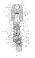
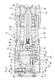
- the illustrated pressing apparatus 1 has an elongated drive unit 2, at one end of which a pressing tool 3 is coupled, which is suitable for the compression of press fittings, which serve to connect pipe ends.
- the drive unit 2 has, at the end opposite the pressing tool 3, a drive motor 4 whose output shaft 5 is coupled to a pump shaft 6 of a hydraulic pump designated as a whole by 7.
- the pump shaft 6 is guided in the hydraulic pump 7 in two bearings 8, 9 and has between the two bearings an eccentric 10 which acts via a needle bearing 11 on a radially displaceably guided pump piston 12.
- the pump piston 12 is moved radially back and forth.
- the housing of the hydraulic pump 7 is surrounded on the outside by an elastomeric hose 13 which encloses a hydraulic reservoir 14 between them and the outside of the hydraulic pump 7 in a liquid-tight manner.
- the ends of the tube 13 engage in grooves 15, 16 and are held there from the outside by pushed-over fixing rings 17, 18 in position.
- the hydraulic pump 7 is flanged in the axial direction on the side facing away from the electric motor 4 to a hydraulic motor in the form of a piston-cylinder unit 19.
- the piston-cylinder unit 19 has a hydraulic cylinder 20 which is closed on the hydraulic pump side with an end plate 21.
- a hydraulic piston 22 is guided displaceably. He divides the interior of the hydraulic cylinder 20 in an end plate-side pressure chamber 23 and a rear space 24 a.
- the hydraulic piston 22 is seated on a piston rod 25 which extends on the side facing away from the end plate 21 in the direction of the pressing tool 3.
- a hat-shaped sealing element 26 is inserted, which rests on the inside of the piston rod 25 and thus seals the rear space 24.
- the sealing element 26 also serves to support a piston spring 25 surrounding the coil spring 27, which is supported at the other end on the side remote from the pressure chamber 23 of the hydraulic piston 22.
- the coil spring 27 is formed as a compression spring and consequently endeavors to move the hydraulic piston 22 in the direction of the end plate 21.
- the hydraulic piston 22 remote from the end of the Kolbentsange 25 is rigidly connected outside of the rear space 24 with a spreader 28.
- the spreader 28 has a bearing body 29, are mounted on the two spreader rollers 30, 31 transversely to the axis of the pressing device 1 side by side and freely rotatable in mutual contact.
- Attached to the rear space-side end of the hydraulic cylinder 20 is a holder 32, the two Clutch plates 33, 34 forms, which extend in the axial direction of the pressing device 1.
- the coupling tabs 33, 34 have such a distance from each other that the spreader 28 can move between them.
- end coupling bores are provided which extend transversely to the longitudinal axis of the pressing device 1 and are aligned.
- two mutually parallel pressing tool tabs of which in FIG. 1 only the rear pressing tool tab 35 can be seen.
- Both press tool tabs 35 also have coupling holes that are aligned with each other and have the same diameter as the coupling holes in the coupling tabs 33, 34.
- connection between the coupling tabs 33, 34 and thus the drive unit 2 is made by a coupling pin 36 through passed through all four coupling holes and locked for the purpose of its positional fixation. In this way, the pressing tool 3 is pivotally connected to the drive unit 2.
- the press tool flaps 35 are of identical construction and are arranged congruently and at a distance. They are connected to each other via two hinge pins 37, 38. In the intermediate space between the press tool tabs 35, mirror-shaped press jaw levers 39, 40 are mounted pivotably on the hinge pins 37, 38.
- the pressing jaw levers 39, 40 form semicircular pressing jaws 41, 42 at their outer ends, which in the illustrated, closed state of the pressing tool 3 enclose a pressing space 43.
- a compression spring 44 ensures that the pressing jaw lever 39, 40 take the illustrated closed final pressing position in the idle state.
- the pressing jaw levers 39, 40 form drive surfaces 45, 46, which interact with the cylindrical surfaces of the spreading rollers 30, 31 during the pressing process.
- the hydraulic pump 7, i. their limited by the pump piston 12 pressure chamber has not shown here hydraulic channels on the one hand connection to the hydraulic reservoir 14 and the other to the pressure chamber 23 in the piston-cylinder unit 19.
- a check valve in the hydraulic line to the hydraulic reservoir 14 ensures that the pump piston 12th Upon movement in one direction, hydraulic oil sucks from the hydraulic reservoir 14 and, when moved in the other direction, conveys the sucked-in hydraulic oil into the pressure chamber 23.
- the hydraulic piston 22 and thus also the piston rod 25 and the spreader 28 connected thereto are moved in the direction of the pressing tool 3.
- a pressure relief valve 47 is formed in the form of a needle valve.
- the hydraulic piston 22 has a pressure opening 23 open valve opening 48, which serves as a valve seat for a valve body 49 on the inside. This is loaded in the direction of the valve opening 48 by means of a pressure acting on the rear side of the valve body 49 compression spring 50.
- the compression spring 50 is designed so that it allows a lifting of the valve body 49 only at a certain cut-off pressure in the Druchraum 23.
- the valve body 49 defines a valve chamber 51, which has a connection to the rear space 24 via a hydraulic channel, not shown here. This in turn is connected via a hydraulic channel, also not shown, with the hydraulic reservoir 14. All above-described hydraulic channels form a total of a hydraulic system.
- an emergency valve 52 which is also designed as a needle valve. It has a connecting channel 53 direct connection to the pressure chamber 23.
- the connecting channel 53 narrows into a valve seat insert 54, which forms a valve seat on the inside, on which a valve needle 55 sealingly abuts.
- the valve needle 55 with a Compressed spring 56 loaded.
- This compression spring 56 is designed so that the valve needle 55 only lifts off from the valve seat insert 54 and thus the emergency valve 52 opens when the pressure in the pressure chamber 23 has reached a value which is at least equal to the cut-off, at which the pressure relief valve 47 at normal function opens, but can also lie about it.
- the valve chamber of the emergency valve 52 has a channel, not shown here, connection to the hydraulic reservoir 14, so that the hydraulic fluid in the pressure chamber 23 can flow into the hydraulic reservoir 14 when opening the emergency valve 50.
- a manual override device 57 is provided, with the aid of which it is possible to effect an opening of the emergency valve 52 by external action.
- the manual actuation device 57 has an actuation tappet 58, which is displaceably guided transversely to the axial extension of the valve needle 55 and ends near the tube 13 within the hydraulic reservoir 14.
- actuation tappet 58 is displaceably guided transversely to the axial extension of the valve needle 55 and ends near the tube 13 within the hydraulic reservoir 14.
- a transverse pin 60 passing through the actuating tappet 58 prevents rotation of the actuating tappet 58 and forms a stop for the starting position.
- valve needle 55 At the valve needle end of the actuating plunger 58 is penetrated by the valve needle 55 and forms there an inclined surface 61, against which a contact surface 62 of the valve needle 55 is applied. Due to this coupling, the valve needle 55 is lifted from the valve seat insert 54 against the action of the compression spring 56 when the actuating plunger 58 is moved by applying pressure to the hose 13 in the direction of the valve needle 55. Independently of this, the coupling between actuation tappet 58 and valve needle 55 allows the valve needle 55 to move freely in the opening direction, so that the actuation tappet 58 has no influence on the automatic opening behavior of the emergency valve 52.
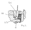
- the output shaft 5 carries a speed sensor 63, on the circumference of the same or unequal distances magnets 64 are distributed.
- the speed sensor 63 opposite is rotationally fixed Speed sensor 65 is arranged, which is capable of detecting the outgoing magnetic fields from the magnet 64 and emits corresponding signals to a control device not shown here. The signals are counted there, the speed of the drive motor 4 being determined from the number determined.
- the control device serves to control the course of the press via the drive motor, as is fundamentally understood from US Pat EP 0 860 220 is known.
- the control device additionally carries out a plausibility check at the end of a pressing operation in order to determine whether a pressing operation has been carried out successfully.
- a measured after opening the pressure relief valve 47 actual load speed of the drive motor 4 is in a predetermined target speed range.
- the upper limit of the target speed range determines the speed that must be fallen below to ensure that a predetermined pressing force has been reached.
- the lower limit for the allowable target load speed range is defined in order to detect overshoots of the permissible pressing force.
- the control device detects the idling speed before the beginning of a compression and predetermines the target load speed range as a function of the measured idling speed. If the determined idle speed is low, so will the load speed when opening the pressure relief valve will be lower, and in the reverse manner, the idle speed is high, so the load speed will be higher. Accordingly, depending on the before the pressing process measured idle speed of the target load speed range specified. This can be determined empirically, for example, and stored in the control device.
- the pressing device 1 is attached to the press fitting after previously compressed the two pressing jaw lever 39, 40 by hand to the spreader 28 adjacent ends against the action of the compression spring 44 and thus the pressing jaws 44 are removed from each other so that the end a mouth-like opening results.
- the pressing tool 3 can then be applied radially to the intended location of the press fitting, wherein the pressing jaws 41, 42 initially come to rest on the press fitting and accordingly the drive surfaces 45, 46 are approximated to each other.
- the electric motor 4 is set in motion via a switch not shown here.
- the idling speed is detected, and in dependence on it a target load speed range is defined, in which the speed of the electric motor 4 must be at the end of a successfully completed pressing operation.
- the hydraulic pump 7 sucks hydraulic fluid from the hydraulic reservoir 14 and conveys it into the pressure chamber 23.
- the lateral surfaces come the spreading rollers 30, 31 on the drive surfaces 45, 46 of the pressing jaw lever 39, 40 for conditioning and spread apart them gradually.
- the pressing jaws 41, 42 approach each other and thus ensure a compression of the press fitting radially inward. This continues until the pressing jaws 41, 42 come into mutual contact, so reach their final pressing position. This gradually increases the pressure in the Pressure chamber 23.
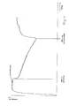
- the speed of the drive motor 4 decreases continuously, as in the FIG. 4 is recognizable.
- the pressure in the pressure chamber 23 still increases until the predetermined cut-off pressure is reached at which the pressure relief valve 47 opens by lifting the valve body 49 of the valve port 48.
- the control device detects the rotational speed of the electric motor 4 when opening the pressure relief valve. If the detected speed is within the predetermined target load speed range, the operator is notified via the signaling device that the pressing operation has been completed successfully.
- the operator turns off the electric motor 4, so that the hydraulic circulation is interrupted.
- an automatic shutdown of the electric motor 4 can take place.
- the rotational speed of the electric motor 4 increases steeply after the opening of the pressure relief valve 47. This speed increase can be used by the control device as a criterion to turn off the electric motor 4.
- the coil spring 27 then pushes the hydraulic piston 22 back towards the end plate 21. In this case, a pressure is generated in the pressure chamber 23, which is sufficient to keep the pressure relief valve 47 open during the entire return movement of the hydraulic piston 22 until the hydraulic piston 22 has reached the starting position shown in the figures again. Then the pressure relief valve 47 closes.
Landscapes
- Engineering & Computer Science (AREA)
- Mechanical Engineering (AREA)
- Manufacturing & Machinery (AREA)
- Fluid-Pressure Circuits (AREA)
- Press Drives And Press Lines (AREA)
Applications Claiming Priority (1)
| Application Number | Priority Date | Filing Date | Title |
|---|---|---|---|
| DE202009003197U DE202009003197U1 (de) | 2009-03-10 | 2009-03-10 | Handführbare Antriebseinrichtung für ein Pressgerät |
Publications (3)
| Publication Number | Publication Date |
|---|---|
| EP2228178A2 true EP2228178A2 (fr) | 2010-09-15 |
| EP2228178A3 EP2228178A3 (fr) | 2011-09-28 |
| EP2228178B1 EP2228178B1 (fr) | 2012-08-22 |
Family
ID=42145927
Family Applications (1)
| Application Number | Title | Priority Date | Filing Date |
|---|---|---|---|
| EP20100155961 Active EP2228178B1 (fr) | 2009-03-10 | 2010-03-09 | Dispositif d'entraînement guidé manuellement pour un appareil de pressage ainsi que procédé de commande d'un dispositif d'entraînement guidé manuellement pour un appareil de pressage |
Country Status (2)
| Country | Link |
|---|---|
| EP (1) | EP2228178B1 (fr) |
| DE (1) | DE202009003197U1 (fr) |
Cited By (2)
| Publication number | Priority date | Publication date | Assignee | Title |
|---|---|---|---|---|
| EP2501523B1 (fr) | 2009-11-17 | 2015-04-29 | Novopress GmbH Pressen und Presswerkzeuge & Co. KG | Presse à guidage manuel |
| EP3643422A1 (fr) * | 2018-10-25 | 2020-04-29 | Von Arx AG | Machine de pressage destinée au pressage d'outils |
Families Citing this family (1)
| Publication number | Priority date | Publication date | Assignee | Title |
|---|---|---|---|---|
| DE202010015365U1 (de) * | 2010-11-11 | 2012-02-15 | Novopress Gmbh Pressen Und Presswerkzeuge & Co. Kg | Prüfgerät |
Citations (2)
| Publication number | Priority date | Publication date | Assignee | Title |
|---|---|---|---|---|
| EP1230998A2 (fr) | 2001-02-12 | 2002-08-14 | Rothenberger Werkzeuge Aktiengesellschaft | Méthode de contrôle automatique d'un outil électro-hydraulique et arrangement approprié |
| US20070033984A1 (en) | 2000-04-28 | 2007-02-15 | Hans-Jorg Goop | Pressing tool and pressing process for extruding press fittings |
Family Cites Families (6)
| Publication number | Priority date | Publication date | Assignee | Title |
|---|---|---|---|---|
| US5125324A (en) | 1988-02-10 | 1992-06-30 | Daia Industry Co. Ltd. | Portable hydraulically operated device incorporating automatic drain valve |
| DE29703052U1 (de) | 1997-02-21 | 1997-04-03 | Novopress GmbH Pressen und Presswerkzeuge & Co KG, 41460 Neuss | Preßgerät zum Verbinden von Werkstücken |
| DE50111613D1 (de) | 2000-05-25 | 2007-01-25 | Arx Ag | Presswerkzeug für die Verpressung von Kupplungselementen |
| US6745611B2 (en) * | 2002-02-19 | 2004-06-08 | Fci Americas Technology, Inc. | Battery powered hydraulic tool |
| DE20303877U1 (de) | 2003-03-10 | 2003-05-08 | Novopress GmbH Pressen und Presswerkzeuge & Co KG, 41460 Neuss | Handgeführtes Preßgerät |
| DE202004000215U1 (de) | 2004-01-08 | 2004-04-01 | Novopress Gmbh Pressen Und Presswerkzeuge & Co Kg | Handgeführtes Preßgerät |
-
2009
- 2009-03-10 DE DE202009003197U patent/DE202009003197U1/de not_active Expired - Lifetime
-
2010
- 2010-03-09 EP EP20100155961 patent/EP2228178B1/fr active Active
Patent Citations (2)
| Publication number | Priority date | Publication date | Assignee | Title |
|---|---|---|---|---|
| US20070033984A1 (en) | 2000-04-28 | 2007-02-15 | Hans-Jorg Goop | Pressing tool and pressing process for extruding press fittings |
| EP1230998A2 (fr) | 2001-02-12 | 2002-08-14 | Rothenberger Werkzeuge Aktiengesellschaft | Méthode de contrôle automatique d'un outil électro-hydraulique et arrangement approprié |
Cited By (3)
| Publication number | Priority date | Publication date | Assignee | Title |
|---|---|---|---|---|
| EP2501523B1 (fr) | 2009-11-17 | 2015-04-29 | Novopress GmbH Pressen und Presswerkzeuge & Co. KG | Presse à guidage manuel |
| EP3643422A1 (fr) * | 2018-10-25 | 2020-04-29 | Von Arx AG | Machine de pressage destinée au pressage d'outils |
| US11772349B2 (en) | 2018-10-25 | 2023-10-03 | Emerson Professional Tools Ag | Pressing tool for pressing workpieces |
Also Published As
| Publication number | Publication date |
|---|---|
| EP2228178B1 (fr) | 2012-08-22 |
| DE202009003197U1 (de) | 2010-05-06 |
| EP2228178A3 (fr) | 2011-09-28 |
Similar Documents
| Publication | Publication Date | Title |
|---|---|---|
| EP2228177B1 (fr) | Dispositif d'entrainement guidé manuellement pour un appareil de pressage ainsi que procédé de commande d'un dispositif d'entraînement guidé manuellement pour un appareil de pressage | |
| DE102008024018B4 (de) | Verfahren zum Betreiben eines motorisch betätigten Handverpressgerätes und Handverpressgerät | |
| EP0860220B1 (fr) | Presse | |
| EP3378581A1 (fr) | Dispositif d'assemblage en plusieurs étapes et procédé d'assemblage correspondant | |
| EP1858740B1 (fr) | Procede et dispositif pour commander une chaine cinematique de vehicule a moteur | |
| WO2015185444A1 (fr) | Procédé pour faire fonctionner un système de pinces destiné à être utilisé sur une installation de forage, système de pinces correspondant, programme informatique de mise en œuvre de ce procédé et installation de forage équipée d'un système de pinces | |
| DE102016117313A1 (de) | Verfahren zum Betrieb eines Arbeitsgerätes und Arbeitsgerät | |
| EP3513911B1 (fr) | Machine de pressage | |
| EP3643422B1 (fr) | Machine de pressage destinée au pressage d'outils | |
| EP2228178B1 (fr) | Dispositif d'entraînement guidé manuellement pour un appareil de pressage ainsi que procédé de commande d'un dispositif d'entraînement guidé manuellement pour un appareil de pressage | |
| DE4413190B4 (de) | Druckbegrenzungsventil und Verfahren zum Einstellen eines Öffnungsdruckes an dem Druckbegrenzungsventil | |
| EP3416783A1 (fr) | Dispositif et procédé de conversion d'une force mécanique pour l'entraînement d'un dispositif de compression de raccords à compression | |
| EP3221619A1 (fr) | Procédé pour faire fonctionner un dispositif de boîte de vitesses automatique ainsi que dispositif de boîte de vitesses automatique correspondant | |
| DE202004000215U1 (de) | Handgeführtes Preßgerät | |
| DE10016752A1 (de) | Presswerkzeug und Pressverfahren | |
| EP1388404A1 (fr) | Ensemble hydraulique pour une machine de moulage par injection | |
| EP2189247B1 (fr) | Dispositif d'entraînement pour un appareil de pressage et appareil de pressage doté d'un tel dispositif d'entraînement | |
| EP2286936B1 (fr) | Outil de presse | |
| DE102016219220B4 (de) | Hydraulikantrieb | |
| DE102006032914A1 (de) | Kupplungssteller zur automatischen Betätigung einer Reibungskupplung | |
| DE3109684C2 (de) | Stellvorrichtung zur Erzeugung verschieden großer Linearbewegungen | |
| DE102014216676A1 (de) | Antriebsvorrichtung, Verfahren zum Betreiben der Antriebsvorrichtung und elektro-mechanische Presse | |
| DE102005042593A1 (de) | Vorrichtung und Verfahren zum Betrieb einer kombinierten, hydraulischen Betriebs-und Festellbremse | |
| DE202008002200U1 (de) | Handgeführtes Pressgerät |
Legal Events
| Date | Code | Title | Description |
|---|---|---|---|
| PUAI | Public reference made under article 153(3) epc to a published international application that has entered the european phase |
Free format text: ORIGINAL CODE: 0009012 |
|
| AK | Designated contracting states |
Kind code of ref document: A2 Designated state(s): AT BE BG CH CY CZ DE DK EE ES FI FR GB GR HR HU IE IS IT LI LT LU LV MC MK MT NL NO PL PT RO SE SI SK SM TR |
|
| AX | Request for extension of the european patent |
Extension state: AL BA ME RS |
|
| PUAL | Search report despatched |
Free format text: ORIGINAL CODE: 0009013 |
|
| AK | Designated contracting states |
Kind code of ref document: A3 Designated state(s): AT BE BG CH CY CZ DE DK EE ES FI FR GB GR HR HU IE IS IT LI LT LU LV MC MK MT NL NO PL PT RO SE SI SK SM TR |
|
| AX | Request for extension of the european patent |
Extension state: AL BA ME RS |
|
| RIC1 | Information provided on ipc code assigned before grant |
Ipc: B25B 27/10 20060101AFI20110825BHEP Ipc: H01R 43/042 20060101ALI20110825BHEP Ipc: B25F 5/00 20060101ALI20110825BHEP Ipc: B21D 39/04 20060101ALI20110825BHEP |
|
| 17P | Request for examination filed |
Effective date: 20111119 |
|
| GRAP | Despatch of communication of intention to grant a patent |
Free format text: ORIGINAL CODE: EPIDOSNIGR1 |
|
| RIC1 | Information provided on ipc code assigned before grant |
Ipc: B21D 39/04 20060101ALI20120127BHEP Ipc: B25B 27/10 20060101AFI20120127BHEP Ipc: H01R 43/042 20060101ALI20120127BHEP Ipc: B25F 5/00 20060101ALI20120127BHEP |
|
| GRAS | Grant fee paid |
Free format text: ORIGINAL CODE: EPIDOSNIGR3 |
|
| GRAA | (expected) grant |
Free format text: ORIGINAL CODE: 0009210 |
|
| AK | Designated contracting states |
Kind code of ref document: B1 Designated state(s): AT BE BG CH CY CZ DE DK EE ES FI FR GB GR HR HU IE IS IT LI LT LU LV MC MK MT NL NO PL PT RO SE SI SK SM TR |
|
| REG | Reference to a national code |
Ref country code: GB Ref legal event code: FG4D Free format text: NOT ENGLISH |
|
| REG | Reference to a national code |
Ref country code: CH Ref legal event code: EP |
|
| REG | Reference to a national code |
Ref country code: IE Ref legal event code: FG4D Free format text: LANGUAGE OF EP DOCUMENT: GERMAN |
|
| REG | Reference to a national code |
Ref country code: AT Ref legal event code: REF Ref document number: 571697 Country of ref document: AT Kind code of ref document: T Effective date: 20120915 |
|
| REG | Reference to a national code |
Ref country code: DE Ref legal event code: R096 Ref document number: 502010001121 Country of ref document: DE Effective date: 20121018 |
|
| REG | Reference to a national code |
Ref country code: CH Ref legal event code: NV Representative=s name: ISLER AND PEDRAZZINI AG, CH |
|
| REG | Reference to a national code |
Ref country code: NL Ref legal event code: VDEP Effective date: 20120822 |
|
| REG | Reference to a national code |
Ref country code: LT Ref legal event code: MG4D Effective date: 20120822 |
|
| PG25 | Lapsed in a contracting state [announced via postgrant information from national office to epo] |
Ref country code: FI Free format text: LAPSE BECAUSE OF FAILURE TO SUBMIT A TRANSLATION OF THE DESCRIPTION OR TO PAY THE FEE WITHIN THE PRESCRIBED TIME-LIMIT Effective date: 20120822 Ref country code: IS Free format text: LAPSE BECAUSE OF FAILURE TO SUBMIT A TRANSLATION OF THE DESCRIPTION OR TO PAY THE FEE WITHIN THE PRESCRIBED TIME-LIMIT Effective date: 20121222 Ref country code: LT Free format text: LAPSE BECAUSE OF FAILURE TO SUBMIT A TRANSLATION OF THE DESCRIPTION OR TO PAY THE FEE WITHIN THE PRESCRIBED TIME-LIMIT Effective date: 20120822 Ref country code: HR Free format text: LAPSE BECAUSE OF FAILURE TO SUBMIT A TRANSLATION OF THE DESCRIPTION OR TO PAY THE FEE WITHIN THE PRESCRIBED TIME-LIMIT Effective date: 20120822 Ref country code: NO Free format text: LAPSE BECAUSE OF FAILURE TO SUBMIT A TRANSLATION OF THE DESCRIPTION OR TO PAY THE FEE WITHIN THE PRESCRIBED TIME-LIMIT Effective date: 20121122 |
|
| PG25 | Lapsed in a contracting state [announced via postgrant information from national office to epo] |
Ref country code: PT Free format text: LAPSE BECAUSE OF FAILURE TO SUBMIT A TRANSLATION OF THE DESCRIPTION OR TO PAY THE FEE WITHIN THE PRESCRIBED TIME-LIMIT Effective date: 20121224 Ref country code: SE Free format text: LAPSE BECAUSE OF FAILURE TO SUBMIT A TRANSLATION OF THE DESCRIPTION OR TO PAY THE FEE WITHIN THE PRESCRIBED TIME-LIMIT Effective date: 20120822 Ref country code: SI Free format text: LAPSE BECAUSE OF FAILURE TO SUBMIT A TRANSLATION OF THE DESCRIPTION OR TO PAY THE FEE WITHIN THE PRESCRIBED TIME-LIMIT Effective date: 20120822 Ref country code: LV Free format text: LAPSE BECAUSE OF FAILURE TO SUBMIT A TRANSLATION OF THE DESCRIPTION OR TO PAY THE FEE WITHIN THE PRESCRIBED TIME-LIMIT Effective date: 20120822 Ref country code: GR Free format text: LAPSE BECAUSE OF FAILURE TO SUBMIT A TRANSLATION OF THE DESCRIPTION OR TO PAY THE FEE WITHIN THE PRESCRIBED TIME-LIMIT Effective date: 20121123 |
|
| PG25 | Lapsed in a contracting state [announced via postgrant information from national office to epo] |
Ref country code: NL Free format text: LAPSE BECAUSE OF FAILURE TO SUBMIT A TRANSLATION OF THE DESCRIPTION OR TO PAY THE FEE WITHIN THE PRESCRIBED TIME-LIMIT Effective date: 20120822 |
|
| PG25 | Lapsed in a contracting state [announced via postgrant information from national office to epo] |
Ref country code: RO Free format text: LAPSE BECAUSE OF FAILURE TO SUBMIT A TRANSLATION OF THE DESCRIPTION OR TO PAY THE FEE WITHIN THE PRESCRIBED TIME-LIMIT Effective date: 20120822 Ref country code: EE Free format text: LAPSE BECAUSE OF FAILURE TO SUBMIT A TRANSLATION OF THE DESCRIPTION OR TO PAY THE FEE WITHIN THE PRESCRIBED TIME-LIMIT Effective date: 20120822 Ref country code: DK Free format text: LAPSE BECAUSE OF FAILURE TO SUBMIT A TRANSLATION OF THE DESCRIPTION OR TO PAY THE FEE WITHIN THE PRESCRIBED TIME-LIMIT Effective date: 20120822 Ref country code: ES Free format text: LAPSE BECAUSE OF FAILURE TO SUBMIT A TRANSLATION OF THE DESCRIPTION OR TO PAY THE FEE WITHIN THE PRESCRIBED TIME-LIMIT Effective date: 20121203 |
|
| PG25 | Lapsed in a contracting state [announced via postgrant information from national office to epo] |
Ref country code: SK Free format text: LAPSE BECAUSE OF FAILURE TO SUBMIT A TRANSLATION OF THE DESCRIPTION OR TO PAY THE FEE WITHIN THE PRESCRIBED TIME-LIMIT Effective date: 20120822 Ref country code: PL Free format text: LAPSE BECAUSE OF FAILURE TO SUBMIT A TRANSLATION OF THE DESCRIPTION OR TO PAY THE FEE WITHIN THE PRESCRIBED TIME-LIMIT Effective date: 20120822 |
|
| PLBE | No opposition filed within time limit |
Free format text: ORIGINAL CODE: 0009261 |
|
| STAA | Information on the status of an ep patent application or granted ep patent |
Free format text: STATUS: NO OPPOSITION FILED WITHIN TIME LIMIT |
|
| 26N | No opposition filed |
Effective date: 20130523 |
|
| PG25 | Lapsed in a contracting state [announced via postgrant information from national office to epo] |
Ref country code: BG Free format text: LAPSE BECAUSE OF FAILURE TO SUBMIT A TRANSLATION OF THE DESCRIPTION OR TO PAY THE FEE WITHIN THE PRESCRIBED TIME-LIMIT Effective date: 20121122 |
|
| REG | Reference to a national code |
Ref country code: DE Ref legal event code: R097 Ref document number: 502010001121 Country of ref document: DE Effective date: 20130523 |
|
| BERE | Be: lapsed |
Owner name: NOVOPRESS G.M.B.H. PRESSEN UND PRESSWERKZEUGE & C Effective date: 20130331 |
|
| PG25 | Lapsed in a contracting state [announced via postgrant information from national office to epo] |
Ref country code: MC Free format text: LAPSE BECAUSE OF NON-PAYMENT OF DUE FEES Effective date: 20130331 |
|
| PG25 | Lapsed in a contracting state [announced via postgrant information from national office to epo] |
Ref country code: CY Free format text: LAPSE BECAUSE OF FAILURE TO SUBMIT A TRANSLATION OF THE DESCRIPTION OR TO PAY THE FEE WITHIN THE PRESCRIBED TIME-LIMIT Effective date: 20120822 |
|
| REG | Reference to a national code |
Ref country code: FR Ref legal event code: ST Effective date: 20131129 |
|
| REG | Reference to a national code |
Ref country code: IE Ref legal event code: MM4A |
|
| PG25 | Lapsed in a contracting state [announced via postgrant information from national office to epo] |
Ref country code: IE Free format text: LAPSE BECAUSE OF NON-PAYMENT OF DUE FEES Effective date: 20130309 Ref country code: BE Free format text: LAPSE BECAUSE OF NON-PAYMENT OF DUE FEES Effective date: 20130331 Ref country code: FR Free format text: LAPSE BECAUSE OF NON-PAYMENT OF DUE FEES Effective date: 20130402 |
|
| PG25 | Lapsed in a contracting state [announced via postgrant information from national office to epo] |
Ref country code: MT Free format text: LAPSE BECAUSE OF FAILURE TO SUBMIT A TRANSLATION OF THE DESCRIPTION OR TO PAY THE FEE WITHIN THE PRESCRIBED TIME-LIMIT Effective date: 20120822 |
|
| GBPC | Gb: european patent ceased through non-payment of renewal fee |
Effective date: 20140309 |
|
| PG25 | Lapsed in a contracting state [announced via postgrant information from national office to epo] |
Ref country code: GB Free format text: LAPSE BECAUSE OF NON-PAYMENT OF DUE FEES Effective date: 20140309 |
|
| PG25 | Lapsed in a contracting state [announced via postgrant information from national office to epo] |
Ref country code: SM Free format text: LAPSE BECAUSE OF FAILURE TO SUBMIT A TRANSLATION OF THE DESCRIPTION OR TO PAY THE FEE WITHIN THE PRESCRIBED TIME-LIMIT Effective date: 20120822 |
|
| PG25 | Lapsed in a contracting state [announced via postgrant information from national office to epo] |
Ref country code: TR Free format text: LAPSE BECAUSE OF FAILURE TO SUBMIT A TRANSLATION OF THE DESCRIPTION OR TO PAY THE FEE WITHIN THE PRESCRIBED TIME-LIMIT Effective date: 20120822 |
|
| PG25 | Lapsed in a contracting state [announced via postgrant information from national office to epo] |
Ref country code: HU Free format text: LAPSE BECAUSE OF FAILURE TO SUBMIT A TRANSLATION OF THE DESCRIPTION OR TO PAY THE FEE WITHIN THE PRESCRIBED TIME-LIMIT; INVALID AB INITIO Effective date: 20100309 Ref country code: MK Free format text: LAPSE BECAUSE OF FAILURE TO SUBMIT A TRANSLATION OF THE DESCRIPTION OR TO PAY THE FEE WITHIN THE PRESCRIBED TIME-LIMIT Effective date: 20120822 Ref country code: LU Free format text: LAPSE BECAUSE OF NON-PAYMENT OF DUE FEES Effective date: 20130309 |
|
| PGFP | Annual fee paid to national office [announced via postgrant information from national office to epo] |
Ref country code: AT Payment date: 20160318 Year of fee payment: 7 |
|
| REG | Reference to a national code |
Ref country code: AT Ref legal event code: MM01 Ref document number: 571697 Country of ref document: AT Kind code of ref document: T Effective date: 20170309 |
|
| PG25 | Lapsed in a contracting state [announced via postgrant information from national office to epo] |
Ref country code: AT Free format text: LAPSE BECAUSE OF NON-PAYMENT OF DUE FEES Effective date: 20170309 |
|
| P01 | Opt-out of the competence of the unified patent court (upc) registered |
Effective date: 20230530 |
|
| PGFP | Annual fee paid to national office [announced via postgrant information from national office to epo] |
Ref country code: IT Payment date: 20250331 Year of fee payment: 16 |
|
| PGFP | Annual fee paid to national office [announced via postgrant information from national office to epo] |
Ref country code: CH Payment date: 20250401 Year of fee payment: 16 |
|
| REG | Reference to a national code |
Ref country code: CH Ref legal event code: U11 Free format text: ST27 STATUS EVENT CODE: U-0-0-U10-U11 (AS PROVIDED BY THE NATIONAL OFFICE) Effective date: 20260401 |
|
| PGFP | Annual fee paid to national office [announced via postgrant information from national office to epo] |
Ref country code: DE Payment date: 20260316 Year of fee payment: 17 |
|
| PGFP | Annual fee paid to national office [announced via postgrant information from national office to epo] |
Ref country code: CZ Payment date: 20260224 Year of fee payment: 17 |