EP2501523B1 - Presse à guidage manuel - Google Patents
Presse à guidage manuel Download PDFInfo
- Publication number
- EP2501523B1 EP2501523B1 EP10781667.0A EP10781667A EP2501523B1 EP 2501523 B1 EP2501523 B1 EP 2501523B1 EP 10781667 A EP10781667 A EP 10781667A EP 2501523 B1 EP2501523 B1 EP 2501523B1
- Authority
- EP
- European Patent Office
- Prior art keywords
- pressing
- electric motor
- motor
- manually guided
- control device
- Prior art date
- Legal status (The legal status is an assumption and is not a legal conclusion. Google has not performed a legal analysis and makes no representation as to the accuracy of the status listed.)
- Active
Links
Images

Classifications
-
- B—PERFORMING OPERATIONS; TRANSPORTING
- B25—HAND TOOLS; PORTABLE POWER-DRIVEN TOOLS; MANIPULATORS
- B25B—TOOLS OR BENCH DEVICES NOT OTHERWISE PROVIDED FOR, FOR FASTENING, CONNECTING, DISENGAGING, OR HOLDING
- B25B27/00—Hand tools, specially adapted for fitting together or separating parts or objects whether or not involving some deformation, not otherwise provided for
- B25B27/02—Hand tools, specially adapted for fitting together or separating parts or objects whether or not involving some deformation, not otherwise provided for for connecting objects by press fit or detaching same
- B25B27/10—Hand tools, specially adapted for fitting together or separating parts or objects whether or not involving some deformation, not otherwise provided for for connecting objects by press fit or detaching same inserting fittings into hoses
-
- B—PERFORMING OPERATIONS; TRANSPORTING
- B21—MECHANICAL METAL-WORKING WITHOUT ESSENTIALLY REMOVING MATERIAL; PUNCHING METAL
- B21D—WORKING OR PROCESSING OF SHEET METAL OR METAL TUBES, RODS OR PROFILES WITHOUT ESSENTIALLY REMOVING MATERIAL; PUNCHING METAL
- B21D39/00—Application of procedures in order to connect objects or parts, e.g. coating with sheet metal otherwise than by plating; Tube expanders
- B21D39/04—Application of procedures in order to connect objects or parts, e.g. coating with sheet metal otherwise than by plating; Tube expanders of tubes with tubes; of tubes with rods
- B21D39/048—Application of procedures in order to connect objects or parts, e.g. coating with sheet metal otherwise than by plating; Tube expanders of tubes with tubes; of tubes with rods using presses for radially crimping tubular elements
-
- Y—GENERAL TAGGING OF NEW TECHNOLOGICAL DEVELOPMENTS; GENERAL TAGGING OF CROSS-SECTIONAL TECHNOLOGIES SPANNING OVER SEVERAL SECTIONS OF THE IPC; TECHNICAL SUBJECTS COVERED BY FORMER USPC CROSS-REFERENCE ART COLLECTIONS [XRACs] AND DIGESTS
- Y10—TECHNICAL SUBJECTS COVERED BY FORMER USPC
- Y10T—TECHNICAL SUBJECTS COVERED BY FORMER US CLASSIFICATION
- Y10T29/00—Metal working
- Y10T29/53—Means to assemble or disassemble
- Y10T29/5367—Coupling to conduit
Definitions
- the invention relates to a hand-held pressing device for connecting two workpieces.
- the pressing device according to the invention is suitable for connecting a pipe to a press fitting by pressing.
- the invention relates hand-held pressing tools for pressing cable lugs.
- Such hand-held pressing devices have a pressing tool with several pressing jaws.
- the press jaws enclose the press fitting inserted over the pipe in a press tool for pipe connections. By closing the pressing jaws a deformation or pressing of the press fitting and the tube takes place.
- pressing tools for cable lugs these are pressed by closing of pressing jaws, the lug is arranged between at least two pressing jaws.
- One of the press jaws can be fixed here.
- the pressing tool is connected to a usually electro-hydraulic or electromechanical conversion device.
- the conversion device is usually driven by an electric motor with the interposition of a transmission.
- a hydraulic conversion device has a hydraulic pump in which it is Usually is a piston pump or a gear pump. The pump is driven by a brush motor.
- the pumps used through which a high torque must be generated, require a design-related relatively low drive speed of usually 2,000 to 5,000 revolutions per minute.
- a reduction gear is interposed between the motor and the pump.
- a working piston is displaced by the hydraulic medium conveyed by the pump.
- the working piston is connected to the pressing jaws so that high pressing forces can be transmitted to the pressing jaws via the working piston.
- the pressure chamber provided for actuating the working piston is opened by a valve, which is usually designed as a needle valve, so that a sudden pressure reduction takes place in the pressure chamber.
- the pressure reduction leads to a speed increase of the pump, which is detected by a speed sensor and leads to an automatic shutdown of the electric motor.
- a return spring is then used to push back the working piston and thus open the pressing jaws.
- a drive unit for a hand-held pressing device consisting of an electric motor and a hydraulic conversion device.
- the pump driven by the motor delivers a hydraulic medium through which a working piston is displaced.
- the working piston can be connected with a pressing tool.
- Such hand-held pressing devices must be maintained at regular intervals. Investigations have shown that the maintenance interval determining component is the brush motor. Due to the frequent start-up under load and due to the provision of stop functions, in which a short circuit is generated via the brush, the brushes of the brush motor are exposed to very heavy wear.
- the object of the invention is to provide a hand-held pressing device, are realized in the longer maintenance intervals.
- the hand-held pressing device for connecting a pipe to a press fitting by pressing has a pressing tool with several pressing jaws.
- the pressing tool is driven by an electric motor with the interposition of a conversion device.
- the conversion device is, in particular, an electrohydraulic or electromechanical conversion device.
- the electric motor is a brushless electric motor.
- a brushless electric motor has the considerable advantage over the brush motor used in known pressing tools that no wear-prone brushes are provided. By using a brushless electric motor can be omitted due to the heavy loads with high wear brushes. This makes it possible to significantly extend the maintenance cycles.
- the number of compressions that can be carried out between two maintenance operations can in particular be at least doubled or even tripled.
- An inventive advantage of the use of a brushless electric motor for operating the pressing device is that additional functions can be realized in a simple manner by a brushless electric motor or the control device of the brushless electric motor.
- control of the rotational speed which is required to produce a desired torque or a desired pressing force, takes place via a control device connected to or integrated into the electric motor.
- a determination of the current engine speed and the electric motor is turned off at a speed increase.
- a brushless electric motor according to the invention has the advantage that the maintenance costs are reduced, since replacement of the brushes or the entire brush motor is not required.
- the electric motor is an external or internal rotor motor.
- the electric motor is a brushless external rotor motor.
- External rotor motors have the advantage over brushless internal rotor motors that they rotate slower and have a higher torque with the same overall dimension.
- a seven-pole external rotor motor has a stator with twelve slots, each second slot being wound. It follows that the field rotates by 60 ° when changing the phase.
- the bell surrounding the stator or the external rotor in this example has fourteen magnets or seven pole pairs, which are arranged distributed over 360 °.
- the external rotor moves seven times slower than the field, so that the outer rotor rotates by a movement of the field by 60 ° by only 8.57 °. As a result, a low speed is realized in an external rotor.
- the brushless electric motor is directly connected to the converter.
- a mandatory when using brush motors reduction gear can be omitted in this preferred embodiment of the invention.
- the output shaft of the electric motor is connected directly to the hydraulic pump, ie to the drive shaft of the hydraulic pump. Due to the possible omission of the transmission in this embodiment, the cost can be reduced. In particular, however, the required space can be significantly reduced.
- a particular advantage of using the brushless motor with omission or greatly simplifying a reduction gear is that the efficiency can be significantly improved. In particular, due to the friction occurring in the transmission losses occur which can be greatly reduced by a great simplification or even by completely omitting the transmission.
- the output shaft of the electric motor is arranged such that it is coaxial with the drive shaft of the hydraulic pump.
- a simple connection of the shafts can be realized in a small space.
- a determination of the current rotational speed takes place via a control device connected to or integrated into the electric motor.
- the voltage induced in the windings can be used to draw conclusions about the engine speed.
- This speed increase of the motor can be determined in a simple manner via the control device and used to switch off the electric motor.
- the speed sensor required in known pressing devices which is absolutely necessary for determining the speed increase when opening the valve, can be eliminated by the inventive use of a brushless electric motor. As a result, the manufacturing cost can be reduced. In particular, this has the advantage that an important for the function of the pressing device component is replaced by the control device of the engine and thereby a much more reliable speed determination is carried out. Failure of the speed sensor, which can lead to significant damage to the pressing tool, can no longer occur.
- a determination or calculation of the engine torque and / or the pressing force generated by the pressing jaws takes place directly via the parameters of the brushless electric motor.
- the valve which opens the pressure chamber in conventional pressing devices can be omitted or at least greatly simplified.
- the valve, which is opened in known pressing devices upon reaching the pressing force can be simplified in this preferred embodiment, at least in such a way that it is only an emergency valve, which avoids damaging the pressing device in the event of failure of the control device.
- Another advantage of using a brushless electric motor, in particular in connection with the already existing or connected to the electric motor control device, is that upon reaching the set pressing force or when errors occur, the motor can be decelerated by appropriate control commands or by software , The high wear occurring in brush motors, which occurs when braking the motor via the generated short circuit, can thus be avoided.
- Another advantage of using a brushless electric motor is that sensorless commutation is possible.
- the provision of error-prone tachometer for pressing force monitoring or flow control is therefore no longer necessary.
- an adjustment device is provided.
- pressing parameters can be entered in a simple manner, for example, via keys and a display. These are transmitted to the control device of the electric motor, so that an immediate simple control of the electric motor and thus the entire pressing device is possible.
- the desired pressing force it is thus possible for the desired pressing force to be input only via the setting device.
- a mechanical change by which, for example, the pressure point at which the valve opens is varied is not required.
- the construction of the pressing device is considerably simplified. Furthermore, eliminates mechanical components that, in particular due to the high forces that occur, possibly damaged or at least maintenance-intensive.
- the type of pressing tool used it is possible, for example via the setting, to enter the type of pressing tool used.
- This has the advantage that a hand-held pressing device can be provided, in which the pressing tool is replaceable.
- a complex adaptation of the pressing device to the pressing tool is no longer necessary. It is only necessary to enter, for example, a code of the pressing tool.
- an automatic recognition of the type of pressing tool by the pressing device This can be done by an identification of the pressing tool, which is detected in particular automatically by the control device. The user can thus replace the pressing tool and does not have to take care that the corresponding pressing parameters are adjusted. As a result, it is avoided, for example, that the maximum permissible pressing force for a particular pressing tool is exceeded.
- a signal output device is connected to the control device of the brushless electric motor.
- the signal output device can be signaled in a simple way the completion of the compression. Also, the occurrence of disturbances or the need to perform maintenance can be signaled by the signal output device.
- the signal output device may be an acoustic and / or tactile (vibration) signal output device. The particular acoustic signal output can in this case be realized directly by the control device.
- the signal output device may also have a display.
- the hand-held pressing device is operated in a preferred embodiment such that the control device connected to the electric motor, as described above, is used for determining the rotational speed and / or the torque and / or other pressing parameters.
- the controller may also be used to control a signal output device.
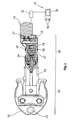
- the hand-held pressing device for connecting pipes by means of a press fitting by pressing has a brushless electric motor 10, the output shaft 12 is connected to an eccentric. About the eccentric pump piston 16 is operated. Further, the brushless electric motor 10 is not for power supply with one represented rechargeable battery, such as a battery or a power supply or the network connected.
- a control valve 18 Via a control valve 18, the hydraulic fluid is supplied to a chamber 20.
- a moving piston 22 in the drawing is moved to the left.
- the left in the figure the end of the working piston 22 is connected to the pressing jaws 24 of the pressing tool 26 -.
- the pressing jaws 24 enclose the pipe, not shown, and surrounding the pipe press fitting, which are arranged in a recess 25.
- the illustrated pressing device thus has three main components, the pressing tool 26, a converting device 28 and the electric motor 10.
- a needle valve 30 is provided which opens the chamber 20 upon reaching the pressing force, so that the pressure in the chamber abruptly decreases. Due to this pressure decrease in the chamber 20, the engine speed increases significantly. This speed increase is detected by a control device 32 which is connected to the brushless electric motor 10, and leads to the switching off of the electric motor 10. As soon as the electric motor 10 is switched off, the working piston 22 is returned to its, in Fig. 1 pushed back home position shown.
- control device 32 may be connected to an adjusting device 34, which is provided in particular on the housing, not shown, of the pressing device.
- the adjustment 34 which has, for example, a display 36 and input buttons 38, pump parameters, press forces, etc. can be selected.
- the inventively provided Brushless electric motor can be used as a signal output device. This can be an acoustic signal output, a tactile signal output, such as the generation of vibrations, or else an optical signal output via a display.
- the already existing display 36 of the adjustment can be used for signal output.
- a further preferred embodiment of a pressing device is a pressing device for cable lugs ( Fig. 2 ).
- This in Fig. 2 schematically illustrated pressing device for cable lugs is shown in a non-sectional side view, the operation of that of the basis Fig. 1 corresponds to described pressing tool.
- a brushless electric motor 10 is also provided according to the invention, which is also connected to an eccentric.
- Within a housing 41 are thus the same components, as by reference Fig. 1 visible, arranged. Only provided for receiving the pressing jaws, substantially cylindrical intermediate part 42 (FIG. Fig. 1 ) deleted. Instead, with the working piston 22 (FIG. Fig. 1 ) Pressing jaws 44 ( Fig. 2 ) connected.
- the pressing jaws 44 are arranged within a pressing jaw head 46.
- the pressing jaw head 46 has an opening 48 into which the crimping cable lug is inserted.
- the structure of the in Fig. 2 illustrated pressing tool, in particular with regard to the design of the drive for the pressing jaws, the basis Fig. 1 described pressing tool.
Landscapes
- Engineering & Computer Science (AREA)
- Mechanical Engineering (AREA)
- Control Of Motors That Do Not Use Commutators (AREA)
- Auxiliary Devices For And Details Of Packaging Control (AREA)
- Battery Mounting, Suspending (AREA)
- Control Of Presses (AREA)
- Press Drives And Press Lines (AREA)
Claims (8)
- Appareil de serrage à main destiné à relier deux pièces, notamment un tuyau équipé d'une monture de serrage par compression, ledit appareil comprenant
un outil de serrage (26) comportant plusieurs mâchoires de serrage (24) et
un moyen de conversion (28) relié à l'outil de serrage (26) et entraîné par un moteur électrique (10),
caractérisé en ce que
le moteur électrique (10) est conçu comme un moteur électrique sans balais,
le moteur électrique (10) est relié à un moyen de commande (32) servant à commander la vitesse de rotation et la détermination de la vitesse de rotation courante du moteur est effectuée à l'aide du moyen de commande (32) et le moteur électrique (10) est arrêté lorsque la vitesse de rotation augmente. - Appareil de serrage à main selon la revendication 1, caractérisé en ce que le moteur électrique (10) est conçu sous la forme d'un moteur à rotor extérieur sans balais.
- Appareil de serrage à main selon la revendication 1, caractérisé en ce que le moteur électrique (10) est conçu sous la forme d'un rotor interne sans balais.
- Appareil de serrage à main selon l'une des revendications 1 à 3, caractérisé en ce que le moteur électrique (10) est relié directement au moyen de conversion (28), notamment à une pompe hydraulique (16) du moyen de conversion (28).
- Appareil de serrage à main selon la revendication 1 à 4, caractérisé en ce que la détermination du couple du moteur et/ou de la force de serrage générée par les mâchoires de serrage (24) est effectuée à l'aide du moyen de commande (32).
- Appareil de serrage à main selon l'une des revendications 1 à 5, caractérisé par un moyen de réglage (34) relié au moyen de commande (32) et servant à entrer des paramètres de serrage.
- Appareil de serrage à main selon la revendication 1 à 6, caractérisé par un moyen de sortie de signal (40) relié au moyen de commande (32).
- Procédé pour faire fonctionner un moyen de serrage à main selon l'une des revendications 1 à 7, dans lequel on démarre la compression,
on détecte la tension induite dans les enroulements du moteur,
on détermine la vitesse de rotation du moteur en se fondant sur la tension détectée et
on arrête le moteur lorsque la vitesse de rotation augmente.
Applications Claiming Priority (2)
| Application Number | Priority Date | Filing Date | Title |
|---|---|---|---|
| DE202009015515U DE202009015515U1 (de) | 2009-11-17 | 2009-11-17 | Handgeführtes Pressgerät |
| PCT/EP2010/067641 WO2011061212A1 (fr) | 2009-11-17 | 2010-11-17 | Presse à guidage manuel |
Publications (3)
| Publication Number | Publication Date |
|---|---|
| EP2501523A1 EP2501523A1 (fr) | 2012-09-26 |
| EP2501523B1 true EP2501523B1 (fr) | 2015-04-29 |
| EP2501523B2 EP2501523B2 (fr) | 2023-04-19 |
Family
ID=43536575
Family Applications (1)
| Application Number | Title | Priority Date | Filing Date |
|---|---|---|---|
| EP10781667.0A Active EP2501523B2 (fr) | 2009-11-17 | 2010-11-17 | Presse à guidage manuel |
Country Status (6)
| Country | Link |
|---|---|
| US (1) | US20120284981A1 (fr) |
| EP (1) | EP2501523B2 (fr) |
| AU (1) | AU2010320961B2 (fr) |
| DE (1) | DE202009015515U1 (fr) |
| ES (1) | ES2543168T5 (fr) |
| WO (1) | WO2011061212A1 (fr) |
Cited By (5)
| Publication number | Priority date | Publication date | Assignee | Title |
|---|---|---|---|---|
| EP3650176A1 (fr) | 2018-11-07 | 2020-05-13 | Von Arx AG | Machine à presser |
| EP3939746B1 (fr) * | 2018-12-07 | 2023-08-23 | Emerson Professional Tools AG | Machine à presser pourvue d'élément de sécurité |
| WO2024182513A1 (fr) * | 2023-03-01 | 2024-09-06 | Milwaukee Electric Tool Corporation | Outil hydraulique avec moteur électrique à rotor externe |
| US12224545B2 (en) | 2021-06-21 | 2025-02-11 | Milwaukee Electric Tool Corporation | Systems and methods for evaluating crimp applications |
| US12627107B2 (en) | 2021-08-11 | 2026-05-12 | Milwaukee Electric Tool Corporation | System and methods for determining crimp applications and reporting power tool usage |
Families Citing this family (21)
| Publication number | Priority date | Publication date | Assignee | Title |
|---|---|---|---|---|
| DE202009015515U1 (de) | 2009-11-17 | 2011-04-07 | Novopress Gmbh Pressen Und Presswerkzeuge & Co. Kommanditgesellschaft | Handgeführtes Pressgerät |
| DE202011101675U1 (de) * | 2011-06-10 | 2012-09-13 | Novopress Gmbh Pressen Und Presswerkzeuge & Co. Kg | Elektrohydraulisches Pressgerät |
| SE535919C2 (sv) * | 2011-06-30 | 2013-02-19 | Atlas Copco Ind Tech Ab | Elektriskt motordrivet verktyg |
| US10226826B2 (en) | 2013-10-22 | 2019-03-12 | Milwaukee Electric Tool Corporation | Hydraulic power tool |
| JP6720133B2 (ja) * | 2014-07-07 | 2020-07-08 | センブレ エス.ピー.エー. | 流体力学圧縮工具の動作方法、及び、流体力学圧縮工具 |
| DE102015102806B4 (de) | 2015-02-27 | 2025-08-07 | Gustav Klauke Gmbh | Hydraulisch betriebenes Handgerät |
| CN205977914U (zh) | 2015-05-06 | 2017-02-22 | 米沃奇电动工具公司 | 液压动力工具 |
| US10618151B2 (en) | 2015-06-15 | 2020-04-14 | Milwaukee Electric Tool Corporation | Hydraulic crimper tool |
| ITUA20161807A1 (it) * | 2016-03-18 | 2017-09-18 | Cembre Spa | Utensile oleodinamico di compressione o taglio |
| EP3307489B1 (fr) * | 2016-05-06 | 2019-07-03 | Lukas Hydraulik GmbH | Procédé permettant de faire fonctionner un outil de travail ou un appareil de sauvetage et outil de travail ou appareil de sauvetage |
| DE102016111874A1 (de) | 2016-06-29 | 2018-01-04 | Gustav Klauke Gmbh | Verfahren zum Betreiben eines hydraulisch betriebenen Handgerätes sowie hydraulisch betriebenes Handgerät |
| US11911888B2 (en) | 2017-11-28 | 2024-02-27 | Hubbell Incorporated | Force adjusting power tool with interchangeable head |
| EP3731997B1 (fr) * | 2017-12-21 | 2024-06-26 | WS Wieländer + Schill Engineering GmbH & Co. KG | Outil hydraulique pour un dispositif de traction et/ou de pressage |
| CN107900968B (zh) * | 2017-12-25 | 2023-12-15 | 南阳淅减汽车减振器有限公司 | 一种减震器油缸底盖压装装置 |
| EP3513911B2 (fr) | 2018-01-17 | 2025-03-26 | Emerson Professional Tools AG | Machine de pressage |
| JP7083915B2 (ja) * | 2018-04-17 | 2022-06-13 | ルーカス ヒュードラウリク ゲーエムベーハー | 作業装置または救助装置の動作方法、および作業装置または救助装置 |
| EP3643422B8 (fr) * | 2018-10-25 | 2023-07-26 | Emerson Professional Tools AG | Machine de pressage destinée au pressage d'outils |
| DE102019124845B4 (de) * | 2019-09-16 | 2023-11-02 | Viega Technology Gmbh & Co. Kg | Presskraftübersetzer, Presswerkzeug, System und Verfahren zur Herstellung einer dichten Verbindung eines Pressverbinders mit einem Werkstück |
| EP4005733A1 (fr) * | 2020-11-27 | 2022-06-01 | Hilti Aktiengesellschaft | Engrenage excentrique pour une machine-outil |
| EP4006382A1 (fr) | 2020-11-30 | 2022-06-01 | Hilti Aktiengesellschaft | Élément ressort sur le dispositif d'accouplement |
| USD1025732S1 (en) * | 2023-08-03 | 2024-05-07 | Qing Dai | Hydraulic tool |
Citations (24)
| Publication number | Priority date | Publication date | Assignee | Title |
|---|---|---|---|---|
| DE2730142A1 (de) | 1977-07-04 | 1979-01-11 | Papst Motoren Kg | Kollektorloser gleichstrommotor |
| US4603283A (en) | 1985-06-03 | 1986-07-29 | Bodine Electric Company | Variable speed control for a brushless direct current motor |
| US5339013A (en) | 1990-02-14 | 1994-08-16 | Matsushita Electric Industrial Co., Ltd. | Method and apparatus for driving a brushless motor including varying the duty cycle in response to variations in the rotational speed |
| US5353882A (en) * | 1992-12-18 | 1994-10-11 | Matsushita Electric Industrial Co., Ltd. | Screwing apparatus |
| DE29502032U1 (de) | 1995-02-08 | 1995-03-23 | Rems-Werk Christian Föll und Söhne GmbH & Co, 71332 Waiblingen | Preßwerkzeug |
| WO1996009142A2 (fr) | 1994-09-13 | 1996-03-28 | Framatome Connectors International | Outil portatif dote d'une pompe hydraulique a cylindree variable |
| DE4446504C1 (de) | 1994-12-25 | 1996-03-28 | Rothenberger Werkzeuge Masch | Preßwerkzeug zum radialen Verpressen von Werkstücken |
| US5553478A (en) | 1994-04-08 | 1996-09-10 | Burndy Corporation | Hand-held compression tool |
| US5782610A (en) | 1995-12-07 | 1998-07-21 | Sanden Corp. | Method of stopping scroll compressor that is driven by 3-phase DC motor |
| EP0860220A2 (fr) | 1997-02-21 | 1998-08-26 | NOVOPRESS GMBH PRESSEN UND PRESSWERKZEUGE & CO. KG. | Presse |
| US6123158A (en) * | 1996-08-03 | 2000-09-26 | Wacker-Werke Gmbh & Co., Kg | Electric tool with ducted cooled control electronics |
| EP1125682A2 (fr) | 2000-02-16 | 2001-08-22 | Murata Kikai Kabushiki Kaisha | Presse |
| US20010033742A1 (en) | 2000-01-07 | 2001-10-25 | Weaver J. Michael | Brushless DC motor |
| DE10106360C1 (de) | 2001-02-12 | 2002-07-11 | Rothenberger Werkzeuge Ag | Verfahren zum automatischen Steuern von elektro-hydraulischen Handwerkzeugen und Anordnung hierfür |
| US20030089511A1 (en) | 2001-11-12 | 2003-05-15 | Yukio Tsuneda | Electric tool |
| WO2005122386A1 (fr) | 2004-06-05 | 2005-12-22 | Robert Bosch Gmbh | Outil electrique portatif ou fixe dote d'une unite d'entrainement |
| DE202006001889U1 (de) | 2006-02-03 | 2007-03-08 | Novopress Gmbh Pressen Und Presswerkzeuge & Co. Kg | Antriebseinheit für ein Preßgerät |
| DE102007005837A1 (de) | 2006-02-03 | 2007-08-16 | Novopress Gmbh Pressen Und Presswerkzeuge & Co. Kg | Antriebseinheit für ein Preßgerät |
| DE102006016448A1 (de) | 2006-04-07 | 2007-10-11 | Robert Bosch Gmbh | Elektrowerkzeugmaschine und Verfahren zum Betreiben derselben |
| EP1923978A2 (fr) | 2006-11-17 | 2008-05-21 | Festool GmbH | Ponceuse orbitale avec un moteur sans balai |
| EP1930124A1 (fr) | 2005-09-07 | 2008-06-11 | Yokota Industrial Co., Ltd. | Outil de serrage à chocs électriques |
| DE202009003196U1 (de) | 2009-03-10 | 2010-04-29 | Novopress Gmbh Pressen Und Presswerkzeuge & Co. Kommanditgesellschaft | Handführbare Antriebseinrichtung für ein Pressgerät |
| EP2228178A2 (fr) | 2009-03-10 | 2010-09-15 | Novopress GmbH Pressen und Presswerkzeuge & Co. KG | Dispositif d'entraînement guidé manuellement pour un appareil de pressage ainsi que procédé de commande d'un dispositif d'entraînement guidé manuellement pour un appareil de pressage |
| DE202009015515U1 (de) | 2009-11-17 | 2011-04-07 | Novopress Gmbh Pressen Und Presswerkzeuge & Co. Kommanditgesellschaft | Handgeführtes Pressgerät |
-
2009
- 2009-11-17 DE DE202009015515U patent/DE202009015515U1/de not_active Expired - Lifetime
-
2010
- 2010-11-17 AU AU2010320961A patent/AU2010320961B2/en active Active
- 2010-11-17 US US13/509,164 patent/US20120284981A1/en not_active Abandoned
- 2010-11-17 ES ES10781667T patent/ES2543168T5/es active Active
- 2010-11-17 EP EP10781667.0A patent/EP2501523B2/fr active Active
- 2010-11-17 WO PCT/EP2010/067641 patent/WO2011061212A1/fr not_active Ceased
Patent Citations (27)
| Publication number | Priority date | Publication date | Assignee | Title |
|---|---|---|---|---|
| DE2730142A1 (de) | 1977-07-04 | 1979-01-11 | Papst Motoren Kg | Kollektorloser gleichstrommotor |
| US4603283A (en) | 1985-06-03 | 1986-07-29 | Bodine Electric Company | Variable speed control for a brushless direct current motor |
| US5339013A (en) | 1990-02-14 | 1994-08-16 | Matsushita Electric Industrial Co., Ltd. | Method and apparatus for driving a brushless motor including varying the duty cycle in response to variations in the rotational speed |
| US5353882A (en) * | 1992-12-18 | 1994-10-11 | Matsushita Electric Industrial Co., Ltd. | Screwing apparatus |
| US5553478A (en) | 1994-04-08 | 1996-09-10 | Burndy Corporation | Hand-held compression tool |
| WO1996009142A2 (fr) | 1994-09-13 | 1996-03-28 | Framatome Connectors International | Outil portatif dote d'une pompe hydraulique a cylindree variable |
| DE69530106T2 (de) | 1994-09-13 | 2003-12-18 | Fci, Paris | Durch einen motor angetriebenes hydraulisches werkzeug |
| DE4446504C1 (de) | 1994-12-25 | 1996-03-28 | Rothenberger Werkzeuge Masch | Preßwerkzeug zum radialen Verpressen von Werkstücken |
| DE29502032U1 (de) | 1995-02-08 | 1995-03-23 | Rems-Werk Christian Föll und Söhne GmbH & Co, 71332 Waiblingen | Preßwerkzeug |
| US5782610A (en) | 1995-12-07 | 1998-07-21 | Sanden Corp. | Method of stopping scroll compressor that is driven by 3-phase DC motor |
| US6123158A (en) * | 1996-08-03 | 2000-09-26 | Wacker-Werke Gmbh & Co., Kg | Electric tool with ducted cooled control electronics |
| EP0860220A2 (fr) | 1997-02-21 | 1998-08-26 | NOVOPRESS GMBH PRESSEN UND PRESSWERKZEUGE & CO. KG. | Presse |
| EP0860223B1 (fr) | 1997-02-21 | 2001-12-05 | NOVOPRESS GMBH PRESSEN UND PRESSWERKZEUGE & CO. KG. | Presse pour connecter des pièces |
| US20010033742A1 (en) | 2000-01-07 | 2001-10-25 | Weaver J. Michael | Brushless DC motor |
| EP1125682A2 (fr) | 2000-02-16 | 2001-08-22 | Murata Kikai Kabushiki Kaisha | Presse |
| EP1230998B1 (fr) | 2001-02-12 | 2009-10-21 | Rothenberger Aktiengesellschaft | Méthode de contrôle automatique d'un outil électro-hydraulique et arrangement approprié |
| DE10106360C1 (de) | 2001-02-12 | 2002-07-11 | Rothenberger Werkzeuge Ag | Verfahren zum automatischen Steuern von elektro-hydraulischen Handwerkzeugen und Anordnung hierfür |
| US20030089511A1 (en) | 2001-11-12 | 2003-05-15 | Yukio Tsuneda | Electric tool |
| WO2005122386A1 (fr) | 2004-06-05 | 2005-12-22 | Robert Bosch Gmbh | Outil electrique portatif ou fixe dote d'une unite d'entrainement |
| EP1930124A1 (fr) | 2005-09-07 | 2008-06-11 | Yokota Industrial Co., Ltd. | Outil de serrage à chocs électriques |
| DE102007005837A1 (de) | 2006-02-03 | 2007-08-16 | Novopress Gmbh Pressen Und Presswerkzeuge & Co. Kg | Antriebseinheit für ein Preßgerät |
| DE202006001889U1 (de) | 2006-02-03 | 2007-03-08 | Novopress Gmbh Pressen Und Presswerkzeuge & Co. Kg | Antriebseinheit für ein Preßgerät |
| DE102006016448A1 (de) | 2006-04-07 | 2007-10-11 | Robert Bosch Gmbh | Elektrowerkzeugmaschine und Verfahren zum Betreiben derselben |
| EP1923978A2 (fr) | 2006-11-17 | 2008-05-21 | Festool GmbH | Ponceuse orbitale avec un moteur sans balai |
| DE202009003196U1 (de) | 2009-03-10 | 2010-04-29 | Novopress Gmbh Pressen Und Presswerkzeuge & Co. Kommanditgesellschaft | Handführbare Antriebseinrichtung für ein Pressgerät |
| EP2228178A2 (fr) | 2009-03-10 | 2010-09-15 | Novopress GmbH Pressen und Presswerkzeuge & Co. KG | Dispositif d'entraînement guidé manuellement pour un appareil de pressage ainsi que procédé de commande d'un dispositif d'entraînement guidé manuellement pour un appareil de pressage |
| DE202009015515U1 (de) | 2009-11-17 | 2011-04-07 | Novopress Gmbh Pressen Und Presswerkzeuge & Co. Kommanditgesellschaft | Handgeführtes Pressgerät |
Non-Patent Citations (6)
| Title |
|---|
| "RS-775VC/WC", DATENBLATT ZU GLEICHSTROMMOTOR MABUCHI RS-775WC, XP055290688, Retrieved from the Internet <URL:http://www.mabuchi-motor.co.jp/cgi-bin/catalog/e_catalog.cgi?CAT_ID=rs_775vcwc> |
| "Switched Reluctance Motor and Drive for Laundry Application", APPLIANCE MANUFACTURER, 1 January 1999 (1999-01-01), pages 38, XP055103547 * |
| ANONYMOUS: "Außenläufer", WIKIPEDIA, XP055290644, Retrieved from the Internet <URL:https://de.wikipedia.org/wiki/Außenläufer> |
| HEIKO HEMBACH: "Systematischer Vergleich von BLDC-Motorkonzepten mit Anwendung auf nass laufende Wasserpumpen kleiner Leistung", DISSERTATION, 18 October 2007 (2007-10-18), pages 6pp, 1 - 153, XP055290677, Retrieved from the Internet <URL:http://athene-forschung.unibw.de/node?id=86268> |
| IKZ PRAXIS, 1 May 2007 (2007-05-01), XP055290689, Retrieved from the Internet <URL:http://www.ikz.de/uploads/media/IKZPX_200705_961_Produkte.pdf> |
| LEANDRO CRAVERO: "Entwurf, Auslegung und Betriebsverhalten von dauermagneterregten bürstenlosen Motoren kleiner Leistung", DISSERTATION, 26 September 2005 (2005-09-26), pages 11, XP055290673, Retrieved from the Internet <URL:https://www.db-thueringen.de/servlets/MCRFileNodeServlet/dbt_derivate_00008046/ilm1-2005000236.pdf> |
Cited By (6)
| Publication number | Priority date | Publication date | Assignee | Title |
|---|---|---|---|---|
| EP3650176A1 (fr) | 2018-11-07 | 2020-05-13 | Von Arx AG | Machine à presser |
| US11213938B2 (en) | 2018-11-07 | 2022-01-04 | Von Arx Ag | Pressing tool |
| EP3939746B1 (fr) * | 2018-12-07 | 2023-08-23 | Emerson Professional Tools AG | Machine à presser pourvue d'élément de sécurité |
| US12224545B2 (en) | 2021-06-21 | 2025-02-11 | Milwaukee Electric Tool Corporation | Systems and methods for evaluating crimp applications |
| US12627107B2 (en) | 2021-08-11 | 2026-05-12 | Milwaukee Electric Tool Corporation | System and methods for determining crimp applications and reporting power tool usage |
| WO2024182513A1 (fr) * | 2023-03-01 | 2024-09-06 | Milwaukee Electric Tool Corporation | Outil hydraulique avec moteur électrique à rotor externe |
Also Published As
| Publication number | Publication date |
|---|---|
| ES2543168T3 (es) | 2015-08-17 |
| AU2010320961A1 (en) | 2012-05-31 |
| DE202009015515U1 (de) | 2011-04-07 |
| EP2501523B2 (fr) | 2023-04-19 |
| AU2010320961B2 (en) | 2015-10-08 |
| ES2543168T5 (es) | 2023-10-04 |
| EP2501523A1 (fr) | 2012-09-26 |
| WO2011061212A1 (fr) | 2011-05-26 |
| US20120284981A1 (en) | 2012-11-15 |
| HK1175436A1 (en) | 2013-07-05 |
Similar Documents
| Publication | Publication Date | Title |
|---|---|---|
| EP2501523B2 (fr) | Presse à guidage manuel | |
| DE102013105703B4 (de) | Nietgerät | |
| EP3643422B1 (fr) | Machine de pressage destinée au pressage d'outils | |
| EP2984241A1 (fr) | Ensemble de damage par vibrations et procédé de fonctionnement d'un ensemble de damage par vibrations | |
| EP3650176B1 (fr) | Machine à presser | |
| EP2986846B1 (fr) | Mécanisme d'entraînement et procédé servant à faire fonctionner un mécanisme d'entraînement de ce type | |
| DE102010020573A1 (de) | Verfahren zum Betrieb eines Hybridantriebs und Hybridantrieb | |
| DE102016210598B4 (de) | Antrieb für einen tür- oder fensterflügel | |
| DE102014206230A1 (de) | Schwingungsdämpfer | |
| WO2014166935A2 (fr) | Presse hydraulique | |
| EP2513490B1 (fr) | Méthode d'exploitation d'une machine hydraulique | |
| DE102008044900A1 (de) | Windkraftanlagengetriebe und Hilfsantrieb für ein Windkraftanlagengetriebe | |
| DE102013007148A1 (de) | Hydraulischer Pressantrieb mit Energierückspeisung | |
| EP1930149A1 (fr) | Entrainement pour presse à excentrique | |
| WO2003040556A1 (fr) | Procede et dispositif de deceleration d'un rotor d'un convertisseur d'energie eolienne | |
| DE102012215810A1 (de) | Bolzenschneider mit ausfahrbarem Geräteelement und einer hydraulischen oder elektrischen Einheit als Antrieb | |
| EP2593679B1 (fr) | Groupe hydraulique | |
| EP2316639B1 (fr) | Procédé et dispositif de réglage de l'entraînement de presses à balles | |
| EP2545808B1 (fr) | Système de guidage pour tiroir et système d'actionnement pour élément de meuble | |
| EP2700149B1 (fr) | Dispositif d'entraînement | |
| EP2431166A1 (fr) | Système de commande pour presse de pliage | |
| EP3380314B1 (fr) | Procédé de fonctionnement d'une presse, en particulier d'une presse d'estampage à vilebrequin | |
| EP2088487A1 (fr) | Dispositif d'entraînement | |
| DE102004024770B4 (de) | Sicherheitsprüfung von Maschinenbremsen | |
| DE102010033346B3 (de) | Verfahren zum Starten eines Elektromotors in einer hydraulisch betriebenen Arbeitsmaschine |
Legal Events
| Date | Code | Title | Description |
|---|---|---|---|
| PUAI | Public reference made under article 153(3) epc to a published international application that has entered the european phase |
Free format text: ORIGINAL CODE: 0009012 |
|
| 17P | Request for examination filed |
Effective date: 20120426 |
|
| AK | Designated contracting states |
Kind code of ref document: A1 Designated state(s): AL AT BE BG CH CY CZ DE DK EE ES FI FR GB GR HR HU IE IS IT LI LT LU LV MC MK MT NL NO PL PT RO RS SE SI SK SM TR |
|
| DAX | Request for extension of the european patent (deleted) | ||
| 17Q | First examination report despatched |
Effective date: 20130430 |
|
| REG | Reference to a national code |
Ref country code: HK Ref legal event code: DE Ref document number: 1175436 Country of ref document: HK |
|
| GRAP | Despatch of communication of intention to grant a patent |
Free format text: ORIGINAL CODE: EPIDOSNIGR1 |
|
| INTG | Intention to grant announced |
Effective date: 20141022 |
|
| GRAS | Grant fee paid |
Free format text: ORIGINAL CODE: EPIDOSNIGR3 |
|
| GRAP | Despatch of communication of intention to grant a patent |
Free format text: ORIGINAL CODE: EPIDOSNIGR1 |
|
| INTG | Intention to grant announced |
Effective date: 20150306 |
|
| GRAA | (expected) grant |
Free format text: ORIGINAL CODE: 0009210 |
|
| AK | Designated contracting states |
Kind code of ref document: B1 Designated state(s): AL AT BE BG CH CY CZ DE DK EE ES FI FR GB GR HR HU IE IS IT LI LT LU LV MC MK MT NL NO PL PT RO RS SE SI SK SM TR |
|
| REG | Reference to a national code |
Ref country code: GB Ref legal event code: FG4D Free format text: NOT ENGLISH |
|
| REG | Reference to a national code |
Ref country code: CH Ref legal event code: EP |
|
| REG | Reference to a national code |
Ref country code: AT Ref legal event code: REF Ref document number: 724171 Country of ref document: AT Kind code of ref document: T Effective date: 20150515 |
|
| REG | Reference to a national code |
Ref country code: IE Ref legal event code: FG4D Free format text: LANGUAGE OF EP DOCUMENT: GERMAN |
|
| REG | Reference to a national code |
Ref country code: DE Ref legal event code: R096 Ref document number: 502010009449 Country of ref document: DE Effective date: 20150611 |
|
| REG | Reference to a national code |
Ref country code: SE Ref legal event code: TRGR |
|
| REG | Reference to a national code |
Ref country code: ES Ref legal event code: FG2A Ref document number: 2543168 Country of ref document: ES Kind code of ref document: T3 Effective date: 20150817 |
|
| REG | Reference to a national code |
Ref country code: NL Ref legal event code: VDEP Effective date: 20150429 |
|
| REG | Reference to a national code |
Ref country code: LT Ref legal event code: MG4D |
|
| PG25 | Lapsed in a contracting state [announced via postgrant information from national office to epo] |
Ref country code: NL Free format text: LAPSE BECAUSE OF FAILURE TO SUBMIT A TRANSLATION OF THE DESCRIPTION OR TO PAY THE FEE WITHIN THE PRESCRIBED TIME-LIMIT Effective date: 20150429 |
|
| PG25 | Lapsed in a contracting state [announced via postgrant information from national office to epo] |
Ref country code: HR Free format text: LAPSE BECAUSE OF FAILURE TO SUBMIT A TRANSLATION OF THE DESCRIPTION OR TO PAY THE FEE WITHIN THE PRESCRIBED TIME-LIMIT Effective date: 20150429 Ref country code: FI Free format text: LAPSE BECAUSE OF FAILURE TO SUBMIT A TRANSLATION OF THE DESCRIPTION OR TO PAY THE FEE WITHIN THE PRESCRIBED TIME-LIMIT Effective date: 20150429 Ref country code: LT Free format text: LAPSE BECAUSE OF FAILURE TO SUBMIT A TRANSLATION OF THE DESCRIPTION OR TO PAY THE FEE WITHIN THE PRESCRIBED TIME-LIMIT Effective date: 20150429 Ref country code: PT Free format text: LAPSE BECAUSE OF FAILURE TO SUBMIT A TRANSLATION OF THE DESCRIPTION OR TO PAY THE FEE WITHIN THE PRESCRIBED TIME-LIMIT Effective date: 20150831 Ref country code: NO Free format text: LAPSE BECAUSE OF FAILURE TO SUBMIT A TRANSLATION OF THE DESCRIPTION OR TO PAY THE FEE WITHIN THE PRESCRIBED TIME-LIMIT Effective date: 20150729 |
|
| REG | Reference to a national code |
Ref country code: FR Ref legal event code: PLFP Year of fee payment: 6 |
|
| PG25 | Lapsed in a contracting state [announced via postgrant information from national office to epo] |
Ref country code: LV Free format text: LAPSE BECAUSE OF FAILURE TO SUBMIT A TRANSLATION OF THE DESCRIPTION OR TO PAY THE FEE WITHIN THE PRESCRIBED TIME-LIMIT Effective date: 20150429 Ref country code: IS Free format text: LAPSE BECAUSE OF FAILURE TO SUBMIT A TRANSLATION OF THE DESCRIPTION OR TO PAY THE FEE WITHIN THE PRESCRIBED TIME-LIMIT Effective date: 20150829 Ref country code: GR Free format text: LAPSE BECAUSE OF FAILURE TO SUBMIT A TRANSLATION OF THE DESCRIPTION OR TO PAY THE FEE WITHIN THE PRESCRIBED TIME-LIMIT Effective date: 20150730 Ref country code: RS Free format text: LAPSE BECAUSE OF FAILURE TO SUBMIT A TRANSLATION OF THE DESCRIPTION OR TO PAY THE FEE WITHIN THE PRESCRIBED TIME-LIMIT Effective date: 20150429 |
|
| REG | Reference to a national code |
Ref country code: HK Ref legal event code: GR Ref document number: 1175436 Country of ref document: HK |
|
| REG | Reference to a national code |
Ref country code: DE Ref legal event code: R026 Ref document number: 502010009449 Country of ref document: DE |
|
| PG25 | Lapsed in a contracting state [announced via postgrant information from national office to epo] |
Ref country code: EE Free format text: LAPSE BECAUSE OF FAILURE TO SUBMIT A TRANSLATION OF THE DESCRIPTION OR TO PAY THE FEE WITHIN THE PRESCRIBED TIME-LIMIT Effective date: 20150429 Ref country code: DK Free format text: LAPSE BECAUSE OF FAILURE TO SUBMIT A TRANSLATION OF THE DESCRIPTION OR TO PAY THE FEE WITHIN THE PRESCRIBED TIME-LIMIT Effective date: 20150429 |
|
| PLBI | Opposition filed |
Free format text: ORIGINAL CODE: 0009260 |
|
| PLBI | Opposition filed |
Free format text: ORIGINAL CODE: 0009260 |
|
| PG25 | Lapsed in a contracting state [announced via postgrant information from national office to epo] |
Ref country code: PL Free format text: LAPSE BECAUSE OF FAILURE TO SUBMIT A TRANSLATION OF THE DESCRIPTION OR TO PAY THE FEE WITHIN THE PRESCRIBED TIME-LIMIT Effective date: 20150429 Ref country code: RO Free format text: LAPSE BECAUSE OF NON-PAYMENT OF DUE FEES Effective date: 20150429 Ref country code: SK Free format text: LAPSE BECAUSE OF FAILURE TO SUBMIT A TRANSLATION OF THE DESCRIPTION OR TO PAY THE FEE WITHIN THE PRESCRIBED TIME-LIMIT Effective date: 20150429 |
|
| 26 | Opposition filed |
Opponent name: GUSTAV KLAUKE GMBH Effective date: 20160127 |
|
| PLAX | Notice of opposition and request to file observation + time limit sent |
Free format text: ORIGINAL CODE: EPIDOSNOBS2 |
|
| 26 | Opposition filed |
Opponent name: ROTHENBERGER WERKZEUGE GMBH Effective date: 20160129 Opponent name: REHAU AG + CO Effective date: 20160129 |
|
| PG25 | Lapsed in a contracting state [announced via postgrant information from national office to epo] |
Ref country code: SI Free format text: LAPSE BECAUSE OF FAILURE TO SUBMIT A TRANSLATION OF THE DESCRIPTION OR TO PAY THE FEE WITHIN THE PRESCRIBED TIME-LIMIT Effective date: 20150429 |
|
| PLBB | Reply of patent proprietor to notice(s) of opposition received |
Free format text: ORIGINAL CODE: EPIDOSNOBS3 |
|
| PG25 | Lapsed in a contracting state [announced via postgrant information from national office to epo] |
Ref country code: LU Free format text: LAPSE BECAUSE OF FAILURE TO SUBMIT A TRANSLATION OF THE DESCRIPTION OR TO PAY THE FEE WITHIN THE PRESCRIBED TIME-LIMIT Effective date: 20151117 Ref country code: MC Free format text: LAPSE BECAUSE OF FAILURE TO SUBMIT A TRANSLATION OF THE DESCRIPTION OR TO PAY THE FEE WITHIN THE PRESCRIBED TIME-LIMIT Effective date: 20150429 |
|
| REG | Reference to a national code |
Ref country code: IE Ref legal event code: MM4A |
|
| PG25 | Lapsed in a contracting state [announced via postgrant information from national office to epo] |
Ref country code: IE Free format text: LAPSE BECAUSE OF NON-PAYMENT OF DUE FEES Effective date: 20151117 |
|
| REG | Reference to a national code |
Ref country code: FR Ref legal event code: PLFP Year of fee payment: 7 |
|
| PG25 | Lapsed in a contracting state [announced via postgrant information from national office to epo] |
Ref country code: BG Free format text: LAPSE BECAUSE OF FAILURE TO SUBMIT A TRANSLATION OF THE DESCRIPTION OR TO PAY THE FEE WITHIN THE PRESCRIBED TIME-LIMIT Effective date: 20150429 Ref country code: SM Free format text: LAPSE BECAUSE OF FAILURE TO SUBMIT A TRANSLATION OF THE DESCRIPTION OR TO PAY THE FEE WITHIN THE PRESCRIBED TIME-LIMIT Effective date: 20150429 Ref country code: HU Free format text: LAPSE BECAUSE OF FAILURE TO SUBMIT A TRANSLATION OF THE DESCRIPTION OR TO PAY THE FEE WITHIN THE PRESCRIBED TIME-LIMIT; INVALID AB INITIO Effective date: 20101117 |
|
| PG25 | Lapsed in a contracting state [announced via postgrant information from national office to epo] |
Ref country code: CY Free format text: LAPSE BECAUSE OF FAILURE TO SUBMIT A TRANSLATION OF THE DESCRIPTION OR TO PAY THE FEE WITHIN THE PRESCRIBED TIME-LIMIT Effective date: 20150429 |
|
| PG25 | Lapsed in a contracting state [announced via postgrant information from national office to epo] |
Ref country code: BE Free format text: LAPSE BECAUSE OF NON-PAYMENT OF DUE FEES Effective date: 20151130 |
|
| PG25 | Lapsed in a contracting state [announced via postgrant information from national office to epo] |
Ref country code: TR Free format text: LAPSE BECAUSE OF FAILURE TO SUBMIT A TRANSLATION OF THE DESCRIPTION OR TO PAY THE FEE WITHIN THE PRESCRIBED TIME-LIMIT Effective date: 20150429 Ref country code: MT Free format text: LAPSE BECAUSE OF FAILURE TO SUBMIT A TRANSLATION OF THE DESCRIPTION OR TO PAY THE FEE WITHIN THE PRESCRIBED TIME-LIMIT Effective date: 20150429 |
|
| REG | Reference to a national code |
Ref country code: FR Ref legal event code: PLFP Year of fee payment: 8 |
|
| APAH | Appeal reference modified |
Free format text: ORIGINAL CODE: EPIDOSCREFNO |
|
| APAW | Appeal reference deleted |
Free format text: ORIGINAL CODE: EPIDOSDREFNO |
|
| APBM | Appeal reference recorded |
Free format text: ORIGINAL CODE: EPIDOSNREFNO |
|
| APBP | Date of receipt of notice of appeal recorded |
Free format text: ORIGINAL CODE: EPIDOSNNOA2O |
|
| APBQ | Date of receipt of statement of grounds of appeal recorded |
Free format text: ORIGINAL CODE: EPIDOSNNOA3O |
|
| APBQ | Date of receipt of statement of grounds of appeal recorded |
Free format text: ORIGINAL CODE: EPIDOSNNOA3O |
|
| PG25 | Lapsed in a contracting state [announced via postgrant information from national office to epo] |
Ref country code: MK Free format text: LAPSE BECAUSE OF FAILURE TO SUBMIT A TRANSLATION OF THE DESCRIPTION OR TO PAY THE FEE WITHIN THE PRESCRIBED TIME-LIMIT Effective date: 20150429 |
|
| PG25 | Lapsed in a contracting state [announced via postgrant information from national office to epo] |
Ref country code: AL Free format text: LAPSE BECAUSE OF FAILURE TO SUBMIT A TRANSLATION OF THE DESCRIPTION OR TO PAY THE FEE WITHIN THE PRESCRIBED TIME-LIMIT Effective date: 20150429 |
|
| PLAB | Opposition data, opponent's data or that of the opponent's representative modified |
Free format text: ORIGINAL CODE: 0009299OPPO |
|
| R26 | Opposition filed (corrected) |
Opponent name: REHAU INDUSTRIES SE & CO. KG Effective date: 20160129 |
|
| APBU | Appeal procedure closed |
Free format text: ORIGINAL CODE: EPIDOSNNOA9O |
|
| REG | Reference to a national code |
Ref country code: FR Ref legal event code: PLFP Year of fee payment: 13 |
|
| PUAH | Patent maintained in amended form |
Free format text: ORIGINAL CODE: 0009272 |
|
| STAA | Information on the status of an ep patent application or granted ep patent |
Free format text: STATUS: PATENT MAINTAINED AS AMENDED |
|
| 27A | Patent maintained in amended form |
Effective date: 20230419 |
|
| AK | Designated contracting states |
Kind code of ref document: B2 Designated state(s): AL AT BE BG CH CY CZ DE DK EE ES FI FR GB GR HR HU IE IS IT LI LT LU LV MC MK MT NL NO PL PT RO RS SE SI SK SM TR |
|
| REG | Reference to a national code |
Ref country code: DE Ref legal event code: R102 Ref document number: 502010009449 Country of ref document: DE |
|
| P01 | Opt-out of the competence of the unified patent court (upc) registered |
Effective date: 20230530 |
|
| REG | Reference to a national code |
Ref country code: SE Ref legal event code: RPEO |
|
| REG | Reference to a national code |
Ref country code: HK Ref legal event code: AM43 Ref document number: 1175436 Country of ref document: HK |
|
| REG | Reference to a national code |
Ref country code: ES Ref legal event code: DC2A Ref document number: 2543168 Country of ref document: ES Kind code of ref document: T5 Effective date: 20231004 |
|
| REG | Reference to a national code |
Ref country code: CH Ref legal event code: U11 Free format text: ST27 STATUS EVENT CODE: U-0-0-U10-U11 (AS PROVIDED BY THE NATIONAL OFFICE) Effective date: 20251201 |
|
| PGFP | Annual fee paid to national office [announced via postgrant information from national office to epo] |
Ref country code: DE Payment date: 20251117 Year of fee payment: 16 |
|
| PGFP | Annual fee paid to national office [announced via postgrant information from national office to epo] |
Ref country code: GB Payment date: 20251120 Year of fee payment: 16 |
|
| PGFP | Annual fee paid to national office [announced via postgrant information from national office to epo] |
Ref country code: AT Payment date: 20251117 Year of fee payment: 16 |
|
| PGFP | Annual fee paid to national office [announced via postgrant information from national office to epo] |
Ref country code: IT Payment date: 20251128 Year of fee payment: 16 |
|
| PGFP | Annual fee paid to national office [announced via postgrant information from national office to epo] |
Ref country code: FR Payment date: 20251120 Year of fee payment: 16 |
|
| PGFP | Annual fee paid to national office [announced via postgrant information from national office to epo] |
Ref country code: CH Payment date: 20251201 Year of fee payment: 16 Ref country code: SE Payment date: 20251119 Year of fee payment: 16 |
|
| PGFP | Annual fee paid to national office [announced via postgrant information from national office to epo] |
Ref country code: CZ Payment date: 20251104 Year of fee payment: 16 |
|
| PGFP | Annual fee paid to national office [announced via postgrant information from national office to epo] |
Ref country code: ES Payment date: 20251216 Year of fee payment: 16 |