EP2228336A2 - Appareil de refroidissement et de tirage de boisson - Google Patents
Appareil de refroidissement et de tirage de boisson Download PDFInfo
- Publication number
- EP2228336A2 EP2228336A2 EP10002258A EP10002258A EP2228336A2 EP 2228336 A2 EP2228336 A2 EP 2228336A2 EP 10002258 A EP10002258 A EP 10002258A EP 10002258 A EP10002258 A EP 10002258A EP 2228336 A2 EP2228336 A2 EP 2228336A2
- Authority
- EP
- European Patent Office
- Prior art keywords
- beverage
- cooling
- piercing
- container
- holding
- Prior art date
- Legal status (The legal status is an assumption and is not a legal conclusion. Google has not performed a legal analysis and makes no representation as to the accuracy of the status listed.)
- Withdrawn
Links
- 238000001816 cooling Methods 0.000 title claims abstract description 122
- 235000013361 beverage Nutrition 0.000 claims description 270
- 238000004140 cleaning Methods 0.000 claims description 68
- 238000010079 rubber tapping Methods 0.000 claims description 27
- 230000008859 change Effects 0.000 claims description 11
- 239000007788 liquid Substances 0.000 claims description 9
- 238000004891 communication Methods 0.000 claims description 4
- 239000012530 fluid Substances 0.000 claims description 4
- 230000001105 regulatory effect Effects 0.000 claims description 4
- 230000008878 coupling Effects 0.000 claims description 3
- 238000010168 coupling process Methods 0.000 claims description 3
- 238000005859 coupling reaction Methods 0.000 claims description 3
- 238000003780 insertion Methods 0.000 claims description 3
- 230000037431 insertion Effects 0.000 claims description 3
- 235000013405 beer Nutrition 0.000 abstract description 3
- XLYOFNOQVPJJNP-UHFFFAOYSA-N water Substances O XLYOFNOQVPJJNP-UHFFFAOYSA-N 0.000 description 16
- 239000012459 cleaning agent Substances 0.000 description 7
- 238000007789 sealing Methods 0.000 description 5
- 230000001154 acute effect Effects 0.000 description 4
- 239000002826 coolant Substances 0.000 description 4
- 230000015572 biosynthetic process Effects 0.000 description 3
- 238000009434 installation Methods 0.000 description 3
- 238000004519 manufacturing process Methods 0.000 description 3
- 238000000034 method Methods 0.000 description 3
- 230000035515 penetration Effects 0.000 description 3
- 230000008569 process Effects 0.000 description 3
- 238000007599 discharging Methods 0.000 description 2
- 229920001971 elastomer Polymers 0.000 description 2
- 239000000806 elastomer Substances 0.000 description 2
- 239000000463 material Substances 0.000 description 2
- 239000000203 mixture Substances 0.000 description 2
- 230000000149 penetrating effect Effects 0.000 description 2
- 229920005830 Polyurethane Foam Polymers 0.000 description 1
- 230000009471 action Effects 0.000 description 1
- 230000008901 benefit Effects 0.000 description 1
- 230000006835 compression Effects 0.000 description 1
- 238000007906 compression Methods 0.000 description 1
- 230000001419 dependent effect Effects 0.000 description 1
- 239000003599 detergent Substances 0.000 description 1
- 230000035622 drinking Effects 0.000 description 1
- 239000006260 foam Substances 0.000 description 1
- 239000012535 impurity Substances 0.000 description 1
- 239000011810 insulating material Substances 0.000 description 1
- 230000007246 mechanism Effects 0.000 description 1
- 238000004806 packaging method and process Methods 0.000 description 1
- 230000002093 peripheral effect Effects 0.000 description 1
- 239000011496 polyurethane foam Substances 0.000 description 1
- 239000003507 refrigerant Substances 0.000 description 1
- 238000005057 refrigeration Methods 0.000 description 1
- 235000014214 soft drink Nutrition 0.000 description 1
- 239000008399 tap water Substances 0.000 description 1
- 235000020679 tap water Nutrition 0.000 description 1
- 238000005496 tempering Methods 0.000 description 1
Images


Classifications
-
- B—PERFORMING OPERATIONS; TRANSPORTING
- B67—OPENING, CLOSING OR CLEANING BOTTLES, JARS OR SIMILAR CONTAINERS; LIQUID HANDLING
- B67D—DISPENSING, DELIVERING OR TRANSFERRING LIQUIDS, NOT OTHERWISE PROVIDED FOR
- B67D1/00—Apparatus or devices for dispensing beverages on draught
- B67D1/04—Apparatus utilising compressed air or other gas acting directly or indirectly on beverages in storage containers
- B67D1/0406—Apparatus utilising compressed air or other gas acting directly or indirectly on beverages in storage containers with means for carbonating the beverage, or for maintaining its carbonation
-
- B—PERFORMING OPERATIONS; TRANSPORTING
- B67—OPENING, CLOSING OR CLEANING BOTTLES, JARS OR SIMILAR CONTAINERS; LIQUID HANDLING
- B67D—DISPENSING, DELIVERING OR TRANSFERRING LIQUIDS, NOT OTHERWISE PROVIDED FOR
- B67D1/00—Apparatus or devices for dispensing beverages on draught
- B67D1/04—Apparatus utilising compressed air or other gas acting directly or indirectly on beverages in storage containers
- B67D1/0412—Apparatus utilising compressed air or other gas acting directly or indirectly on beverages in storage containers the whole dispensing unit being fixed to the container
- B67D1/0418—Apparatus utilising compressed air or other gas acting directly or indirectly on beverages in storage containers the whole dispensing unit being fixed to the container comprising a CO2 cartridge for dispensing and carbonating the beverage
-
- B—PERFORMING OPERATIONS; TRANSPORTING
- B67—OPENING, CLOSING OR CLEANING BOTTLES, JARS OR SIMILAR CONTAINERS; LIQUID HANDLING
- B67D—DISPENSING, DELIVERING OR TRANSFERRING LIQUIDS, NOT OTHERWISE PROVIDED FOR
- B67D1/00—Apparatus or devices for dispensing beverages on draught
- B67D1/07—Cleaning beverage-dispensing apparatus
-
- B—PERFORMING OPERATIONS; TRANSPORTING
- B67—OPENING, CLOSING OR CLEANING BOTTLES, JARS OR SIMILAR CONTAINERS; LIQUID HANDLING
- B67D—DISPENSING, DELIVERING OR TRANSFERRING LIQUIDS, NOT OTHERWISE PROVIDED FOR
- B67D1/00—Apparatus or devices for dispensing beverages on draught
- B67D1/08—Details
- B67D1/0829—Keg connection means
- B67D1/0841—Details
- B67D1/0842—Multiple connectors, e.g. for simultaneously connecting several containers
-
- B—PERFORMING OPERATIONS; TRANSPORTING
- B67—OPENING, CLOSING OR CLEANING BOTTLES, JARS OR SIMILAR CONTAINERS; LIQUID HANDLING
- B67D—DISPENSING, DELIVERING OR TRANSFERRING LIQUIDS, NOT OTHERWISE PROVIDED FOR
- B67D1/00—Apparatus or devices for dispensing beverages on draught
- B67D1/08—Details
- B67D1/0857—Cooling arrangements
- B67D1/0858—Cooling arrangements using compression systems
- B67D1/0859—Cooling arrangements using compression systems the evaporator being in direct heat contact with the beverage, e.g. placed inside a beverage container
-
- B—PERFORMING OPERATIONS; TRANSPORTING
- B67—OPENING, CLOSING OR CLEANING BOTTLES, JARS OR SIMILAR CONTAINERS; LIQUID HANDLING
- B67D—DISPENSING, DELIVERING OR TRANSFERRING LIQUIDS, NOT OTHERWISE PROVIDED FOR
- B67D1/00—Apparatus or devices for dispensing beverages on draught
- B67D1/08—Details
- B67D1/0857—Cooling arrangements
- B67D1/0858—Cooling arrangements using compression systems
- B67D1/0861—Cooling arrangements using compression systems the evaporator acting through an intermediate heat transfer means
- B67D1/0865—Cooling arrangements using compression systems the evaporator acting through an intermediate heat transfer means by circulating a cooling fluid along beverage supply lines, e.g. pythons
- B67D1/0867—Cooling arrangements using compression systems the evaporator acting through an intermediate heat transfer means by circulating a cooling fluid along beverage supply lines, e.g. pythons the cooling fluid being a liquid
-
- B—PERFORMING OPERATIONS; TRANSPORTING
- B67—OPENING, CLOSING OR CLEANING BOTTLES, JARS OR SIMILAR CONTAINERS; LIQUID HANDLING
- B67D—DISPENSING, DELIVERING OR TRANSFERRING LIQUIDS, NOT OTHERWISE PROVIDED FOR
- B67D1/00—Apparatus or devices for dispensing beverages on draught
- B67D1/08—Details
- B67D1/0878—Safety, warning or controlling devices
- B67D1/0882—Devices for controlling the dispensing conditions
- B67D1/0884—Means for controlling the parameters of the state of the liquid to be dispensed, e.g. temperature, pressure
-
- B—PERFORMING OPERATIONS; TRANSPORTING
- B67—OPENING, CLOSING OR CLEANING BOTTLES, JARS OR SIMILAR CONTAINERS; LIQUID HANDLING
- B67D—DISPENSING, DELIVERING OR TRANSFERRING LIQUIDS, NOT OTHERWISE PROVIDED FOR
- B67D1/00—Apparatus or devices for dispensing beverages on draught
- B67D1/08—Details
- B67D1/0889—Supports
-
- B—PERFORMING OPERATIONS; TRANSPORTING
- B67—OPENING, CLOSING OR CLEANING BOTTLES, JARS OR SIMILAR CONTAINERS; LIQUID HANDLING
- B67D—DISPENSING, DELIVERING OR TRANSFERRING LIQUIDS, NOT OTHERWISE PROVIDED FOR
- B67D1/00—Apparatus or devices for dispensing beverages on draught
- B67D1/08—Details
- B67D1/12—Flow or pressure control devices or systems, e.g. valves, gas pressure control, level control in storage containers
- B67D1/1245—Change-over devices, i.e. connecting a flow line from an empty container to a full one
-
- B—PERFORMING OPERATIONS; TRANSPORTING
- B67—OPENING, CLOSING OR CLEANING BOTTLES, JARS OR SIMILAR CONTAINERS; LIQUID HANDLING
- B67D—DISPENSING, DELIVERING OR TRANSFERRING LIQUIDS, NOT OTHERWISE PROVIDED FOR
- B67D2210/00—Indexing scheme relating to aspects and details of apparatus or devices for dispensing beverages on draught or for controlling flow of liquids under gravity from storage containers for dispensing purposes
- B67D2210/00028—Constructional details
- B67D2210/00031—Housing
-
- B—PERFORMING OPERATIONS; TRANSPORTING
- B67—OPENING, CLOSING OR CLEANING BOTTLES, JARS OR SIMILAR CONTAINERS; LIQUID HANDLING
- B67D—DISPENSING, DELIVERING OR TRANSFERRING LIQUIDS, NOT OTHERWISE PROVIDED FOR
- B67D2210/00—Indexing scheme relating to aspects and details of apparatus or devices for dispensing beverages on draught or for controlling flow of liquids under gravity from storage containers for dispensing purposes
- B67D2210/00028—Constructional details
- B67D2210/00047—Piping
- B67D2210/0006—Manifolds
-
- B—PERFORMING OPERATIONS; TRANSPORTING
- B67—OPENING, CLOSING OR CLEANING BOTTLES, JARS OR SIMILAR CONTAINERS; LIQUID HANDLING
- B67D—DISPENSING, DELIVERING OR TRANSFERRING LIQUIDS, NOT OTHERWISE PROVIDED FOR
- B67D2210/00—Indexing scheme relating to aspects and details of apparatus or devices for dispensing beverages on draught or for controlling flow of liquids under gravity from storage containers for dispensing purposes
- B67D2210/00028—Constructional details
- B67D2210/00099—Temperature control
- B67D2210/00104—Cooling only
Definitions
- the invention relates to a beverage cooling and dispensing device according to the preamble of claim 1 and an arrangement of a beverage cooling and dispensing device and a cleaning container according to claim 14.
- beverage cooling and dispensing devices for home use are known, which are designed for dispensing drinks from low-volume beverage containers, in particular from party drums.
- party kegs are usually made dimensionally stable material and designed to hold 5 or more liters of a drink, especially beer or various soft drinks.
- Such Getränkekühl- and dispensing devices have a piercing device for piercing the beverage container, which communicates with the dispensing device via a hose or pipe system.
- a compressed gas device is provided, which is designed to provide gas, in particular compressed gas within the beverage cooling and dispensing device. The gas provided by the compressed gas device is introduced into the beverage container, thereby expelling the beverage from the beverage container.
- beverage cooling and dispensing devices are equipped with a cooling device.
- the cooling device may for example consist of a heat sink, which is in thermal communication with the beverage container and thus cools the beverage therein.
- a disadvantage of the known devices is that the change of at least one beverage container is usually very cumbersome.
- the devices usually have a puncture, which is introduced from above into an opening of the beverage container and is fixed consuming at the top of the beverage container, especially a party barrel. To change the beverage container, this sword must first be removed and reintroduced into the newly tapped beverage container. This requires practice on most currently available beverage coolers and dispensers.
- the beverage containers are usually included in the housing interior of the beverage cooling and dispensing device, so that a change of the beverage container in addition to the Anstichproblematik requires a cumbersome opening of the device housing.
- the present invention the object of demonstrating a beverage cooling and dispensing device that allows easy and quick change of the beverage container.
- the object is achieved on the basis of the features of the preamble of claim 1 by its characterizing features.
- the piercing device is part of a combined holding piercing device and is designed for the lateral piercing of the beverage container, in particular a party barrel.
- the holding piercing device has at least one first and second holding element, wherein both holding elements for receiving the beverage container are spaced from each other.
- at least one of the holding elements is designed for at least partially embracing the beverage container, wherein the piercing device is provided between the first and second holding element, preferably adjacent to the first holding element.
- the combined holding-piercing device enables a particularly simple fixation of at least one beverage container, in particular a party barrel on the beverage cooling and dispensing device with simultaneous piercing of the beverage container.
- the piercing and the fixation of the beverage container are reduced, in particular a party barrel on a job that allows an easy and quick change of the beverage container.
- the encompassing of the folds of the beverage container allows a very effective fixation of the beverage container.
- the holding piercing device is arranged on the housing of the beverage cooling and tapping device, in particular on the outside of the housing. This makes it possible to attach the drinks container without removing the housing or a part of the housing on the beverage cooling and dispensing device to remove or replace an empty beverage container for a full.
- the holding piercing device is at least partially an integral part of the housing. This has the advantage that at least parts of the holding piercing device can be integrated into the manufacturing process of the housing and thus the production costs are reduced.
- the housing of the beverage cooling and tapping device has a curved into the housing interior area in which the holding piercing device is arranged.
- the first holding element is an arcuate projection on the housing of the beverage cooling and tapping device, which is adapted to the shape and / or the rebate depth of the beverage container.
- the beverage container can be gripped very precisely and thus fixed relative to the housing, on the other hand, the first holding element can be finished together with the entire housing or at least one housing part, which in turn lowers the cost of production.
- the second holding element is a spring-loaded, pivotable, displaceable or elastically bendable latching element.
- Such a design of the second holding element allows pivoting or deformation of the locking element against the spring force or restoring force for introducing a beverage container. Without external force, the locking element pivots back into the starting position and thereby engages in a latching manner the fold at the top of the beverage container, wherein the beverage container is clamped by action of the spring-loaded second holding member like a pliers between the first and second holding element.
- the first holding element forms a hinge point for insertion of the beverage container in the holding piercing device by means of a pivoting movement. This allows a particularly easy introduction of a new beverage container in the beverage cooling and dispensing device according to the invention.
- the piercing device consists of a piercing tube with a pressurized gas supply tube located in the piercing tube interior.
- the piercing device for penetrating the beverage container is formed on the side wall in the vicinity of the underside of the beverage container.
- the piercing tube is preferably surrounded by an elastomer.
- This elastomer is so deformed during the tapping that the tapping point is sealed and the beverage contained in the beverage container can not escape laterally past the piercing device.
- a further preferred embodiment provides for a removal safety device which, depending on the operating state of the beverage cooling and dispensing device, is designed to block the removal of the at least one beverage container from the holding piercing device. This ensures that a beverage container can only be removed from the holding piercing device when the pressure in the beverage container has been reduced. Removing the container from the holding piercing device in case of overpressure in the beverage container would lead to a strong splashing of the beverage and thus to large impurities in the vicinity of the installation location of the beverage cooling and dispensing device.
- the compressed gas device is fed by at least one compressed gas cartridge, preferably by at least one 16 g compressed gas cartridge.
- compressed gas cartridges especially in a 16g standard size are commercially available and cheap, whereby the running costs of the beverage cooling and dispensing device are low.
- At least one tapping unit with quick coupling is provided for piercing the compressed gas cartridge.
- the change of the compressed gas cartridge can also be facilitated in accordance with a further preferred embodiment in that the tapping unit is arranged in a readily accessible from the outside, independently of the rest of the housing easily openable compartment within the housing.
- the cooling device of the beverage cooling and dispensing device has at least one throughflow cooler. This can ensure that cool drink can be tapped after a short time after switching on the beverage cooling and tapping without the beverage container had to be stored cool before.
- the flow cooler on each of the input and output to a device for determining the beverage temperature.
- the temperature of the same can be measured both before the beverage enters the throughflow cooler and after it leaves the beverage, with the aim of always achieving a defined, adjustable beverage temperature, and icing of the throughflow cooler due to excessive cooling to avoid.
- an adjustable pressure regulator and an indication of the pressure applied to the beverage container are provided for regulating the pressure of the compressed gas device.
- a cleaning container which can be connected to the holding piercing device instead of the at least one beverage container, wherein a liquid provided in the cleaning container can be dispensed, for example, by the compressed gas device.
- the dispensing device is designed to be removable.
- intensive cleaning for example with the aid of a brush, is made considerably easier.
- the cleaning container has a first connection element which is suitable for connection to the piercing unit.
- This connection element is matched to the tapping unit and allows a liquid-tight connection of the cleaning container to the beverage cooling and tapping device.
- the cleaning container has means for stationary fixation of the cleaning container in the holding piercing unit, which can be brought into engagement with the first and second holding elements.
- These fixing means enable a firm hold of the cleaning container in the beverage cooling and dispensing device and thereby ensure a firm connection of the connection element of the cleaning container with the tapping unit of the beverage cooling and tapping device.
- the cleaning container is shaped such that it can be inserted into the curved region of the housing and fills it substantially accurately. Due to such a design, the cleaning container is visually inconspicuous integrated into the beverage cooling and dispensing device, on the other hand can thus significantly reduce the packaging size of the beverage cooling and dispensing device.
- the cleaning container has a second connection element for connecting an external pressure or water supply.
- this second connection element it is possible to introduce liquid and / or pressure from the outside into the cleaning container without having to remove it from the beverage cooling and dispensing device. This significantly simplifies the cleaning process.
- first and / or second connection element may have a valve function for closing the cleaning container. This ensures that the cleaning container can be filled with liquid or pressurized without this / these can escape from the cleaning container.
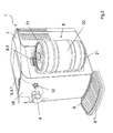
- FIGS. 1 to 3 each show a variant of a beverage cooling and tapping device 1 according to the invention in each case in a perspective view. Moreover, in FIG. 3 the beverage cooling and dispensing device 1 with removed housing side part shown to illustrate the internal structure of the beverage cooling and dispensing device 1 according to the invention.
- the beverage cooling and tapping device 1 is provided for dispensing beverages from at least one beverage container 20, wherein the beverage container 20 is made of a dimensionally stable material and preferably has a cylindrical basic shape.
- the beverage cooling and dispensing device 1 can also be designed to dispense one or different drinks from two separate beverage containers 20 or several beverage containers 20 having chambers.
- a beverage container 20 may be formed for example by a party keg, which is provided for receiving at least five liters of a beverage. Particularly preferred is provided as a beverage container 20, a 5-liter beer keg.
- the beverage cooling and dispensing device 1 has at least one piercing device 2, a cooling device 3, a dispensing device 4 and a compressed gas device 5, wherein, for example, the piercing device 2 is in fluid communication with the dispensing device 4 via the cooling device 3.
- the general mode of operation of the beverage cooling and dispensing device 1 will first be described below.
- the abovementioned devices can hereby be accommodated at least partially in a housing 7.
- the beverage cooling and dispensing device 1 provides a piercing device 2, which is designed to penetrate a wall of a beverage container 20.
- the piercing device 2 is preferably provided for discharging the beverage from the beverage container 20.
- this may be formed for supplying compressed gas into the beverage container interior, wherein said compressed gas is provided by means of the compressed gas device 5.
- the piercing device 2 thus has two functions.
- the introduction of the compressed gas can be realized in the beverage container interior via a separate, additional supply unit.
- an overpressure is created in the beverage container 20, which acts on the beverage contained in the beverage container interior, so that it is discharged via the piercing device 2.
- the piercing device 2 is connected by means of a liquid-tight connecting element, for example a hose or tube with a flow cooler 10 of the cooling device 3.
- a liquid-tight connecting element for example a hose or tube with a flow cooler 10 of the cooling device 3.
- the beverage is heated to a preset beverage temperature and fed via another liquid-tight connecting element, also for example a hose or pipe, the dispensing device 4.
- This tapping device 4 preferably forms a tap, which is at least in a closed and an open position can be brought, wherein in the closed position, the outflow of the beverage from the dispensing device 4 is suppressed and in the open position, a flow of the beverage is possible.
- the piercing device 2 is part of a combined holding piercing device 6 and the clip-on device 2 is designed for the lateral piercing of the beverage container 20, in particular a party barrel.
- the holding piercing device 6 comprises, in addition to the piercing device 2, substantially at least one first and second holding element 6.1, 6.2, which are preferably arranged at a distance from one another.
- FIG. 1 is a side view and in FIG. 4 a lateral sectional view of the holding piercing device 6 according to the invention for lateral piercing and holding the beverage container 20 exemplified.
- the holding piercing device 6 it is irrelevant in which device area, ie the device front or rear side or the two sides of the device, the holding piercing device 6 is provided.
- the first and second holding element 6.1, 6.2 have in the present embodiment, an approximately the height of the male beverage container 20 corresponding distance from each other, with quite different arrangements of the first and second holding element 6.1, 6.2 are possible, the sufficient fixation of the beverage container 20 in the Allow tapping.
- the first and second holding element 6.1, 6.2 may for example be shaped so that they surround a beverage container 20 at least partially and fix it stationary.
- the piercing device 2 is arranged, for example, on an imaginary connecting line between the first and second holding element 6.1, 6.2, preferably adjacent to the first holding element 6.1.
- a variety of drinks is now commercially available in barrel-like or substantially cylindrical beverage containers 20, which each have an annular, circumferential fold 21 on its upper and lower end faces.
- the first and second holding elements 6.1, 6.2 for example, formed such that they at least partially surround the arranged on the upper and lower end of the barrel-like beverage container 20 folds 21.
- the holding-piercing device 6 is integrated in a side wall of the housing 7, in an inwardly curved portion 7.1 of the housing side wall.
- the first holding element 6.1 is formed by a preferably arcuate projection 6.1.1 on the housing 7, wherein the shape and height of the arcuate projection 6.1.1 is adapted to the fold 21, in particular its rebate depth of the male beverage container 20.
- the first holding element 6.1 is formed as the projection 6.1.1 forming ring segment and arranged in or on the housing side wall.
- the first holding element 6.1 can also be realized as designed in the side wall of the housing 7 ring segment-shaped groove.
- the second holding element 6.2 is arranged.
- This second holding element 6.2 is pivoted, bent or displaceable, for example designed to be linearly displaceable, preferably in a direction away from the first holding element 6.1 sliding or pivoting direction, whereby the distance between the first and second holding element 6.1, 6.2 changes, in particular is increased.
- the second holding element 6.2 comprises a ring-segment-shaped groove 6.2.1 and a handle 6.2.2, wherein in the ring-segment-shaped groove 6.2.1 when receiving a beverage container 20 in the holding piercing device 6 at the from the upper end of the beverage container 20 in Direction of the second holding element 6.2 wegumble fold 21 is at least partially received.
- the handle 6.2.2 of the second holding element 6.2 is based on a horizontal plane at an acute angle obliquely upwards and serves as a grip element for actuation by a user, for inserting or dispensing a beverage container 20 in the holding piercing device 6th
- this beverage container 20 is first introduced with its arranged at the bottom fold 21 in the annular segment-shaped intermediate space formed by the arcuate projection 6.1.1 and the inwardly curved portion 7.1 of the housing side wall.
- the beverage container 20 is in this case held obliquely so that the longitudinal axis of the beverage container forms an acute angle with the longitudinal axis of the beverage cooling and dispensing device 1, wherein this acute angle opens towards the top of the beverage cooling and dispensing device 1 according to the invention.
- the beverage container 20 is pivoted with its arranged on the upper end face or top fold 21 in the direction of the second holding element 6.2, wherein the first holding element 6.1 acts as a hinge point for this pivotal movement.
- the distance of the first and second holding element 6.1, 6.2 is slightly smaller than the distance of the arranged on the top and bottom of the beverage container 20 fold 21.
- the second retaining element 6.2 is deflected upward. On the one hand, this can be done by the user pushing the second holding element 6.2 upwards on the handle 6.2.2 or that pressure is exerted on the second holding element 6.2 on the beverage container 20 in the region of the upper fold 21.
- the upper fold 21 is partially against this handle 6.2.2 and slides on this inclined surface under the second holding element 6.2, which is deflected upward. If the upper fold 21 hits the annular segment-shaped groove 6.2.1 of the second holding element 6.2, the second holding element 6.2 engages with its groove 6.2.1 on the fold 21 and surrounds it at least in a form-fitting manner.
- the holding piercing device 6 is the beverage container 20 outside the housing 7, i. is arranged at least partially visible from the outside.
- the advertising printed on the beverage container 20 is visible, i. the user sees which beverage type is currently tapable.
- the holding piercing device 6 may be received by the housing 7.
- the beverage container 20 is pierced simultaneously via the integrated piercing device 2 according to the invention.
- the piercing device 2 stands for this purpose, for example, in the radial direction with respect to the curved portion 7.1 of the housing 7 or at an acute angle from just this, wherein the protruding from the curved portion 7.1 outward element of the piercing 2 with respect to the longitudinal extent is dimensioned such that the introduced into the holding piercing device 6 beverage container 20 with its side wall already clearly before snapping into the second holding element 6.2 in contact with the protruding element of the piercing 2 occurs.
- the outwardly projecting element of the piercing device 2 is preferably formed for penetrating the side wall of the beverage container 20, namely preferably as a lancing tube 2.1.
- the piercing tube 2.1 penetrates below the pressure applied by the user of the pivoting movement of the wall.
- the lancing tube 2.1 preferably so far penetrated into the interior of the beverage container 20 that a removal of the drink by means of the piercing device 2 from the beverage container 20 via the lancing tube 2.1 possible is.
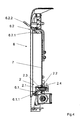
- FIG. 5 is an example of a variant of a piercing device 2 shown in a side sectional view.
- the piercing device 2 essentially consists of a piercing tube 2.1 with a round cross-sectional area, in the piercing tube interior of which a compressed gas feed tube 2.2 is preferably centered.
- the lancing tube 2.1 is preferably obliquely and preferably sharp-edged on its free end facing the beverage container 20, so that only a small portion of the cross-sectional area of the lancing tube 2.1 initially engages when the beverage container 20 is pivoted into the holding piercing device 6 the beverage container wall rests and thereby piercing is much easier.
- the lancing tube 2.1 can also be sharpened at its chamfered free end in order to additionally reduce the pressure to be applied for penetration of the piercing tube 2.1.
- annular channel is formed, through which the beverage is discharged from the beverage container 20.
- a preferably aligned perpendicular to the longitudinal axis of the channel pipe piece connects, which is liquid-tightly connected to the annular channel.
- This pipe section serves as a connecting element 2.4 for liquid-tight connection of a connecting element, which feeds the beverage to the flow cooler 10 of the cooling device 3.
- a connecting element 2.5 is provided, which serves as a connecting element between the compressed gas supply pipe 2.2 and the connecting pipe to the compressed gas device 5.
- a sealing element 2.3 is provided which surrounds the piercing tube 2.1 at its outer peripheral side projecting from the curved region 7.1 of the housing 7.
- the sealing element 2.3 is preferably frusto-conical, with the truncated cone opening in the direction of the housing 7.
- the resulting overpressure acts on the beverage located in the beverage container 20 and discharges it via the annular channel between the inner wall of the piercing tube 2.1 and the outer wall of the compressed gas feed tube 2.2 via the connecting element 2.4. It is ensured by the sealing element 2.3, that even at high pressure in the beverage container 20, the drink can not escape laterally on the lancing tube 2.1 over. Due to the position of the piercing element 2 in the immediate vicinity of the first holding element 6.1 of the beverage container 20 is pierced in the immediate vicinity of the ground on its side wall, so that a nearly complete emptying of the beverage container 20 is possible.
- the pressurized gas introduced through the pressurized gas supply pipe 2.2 is provided by the pressurized gas device 5.
- This is fed by a compressed gas cartridge 5.1, in particular a CO2-compressed gas cartridge, which can be connected by means of a tapping unit with quick coupling device in a short time to the beverage cooling and dispensing device 1.
- the compressed gas cartridge 5.1 can be pierced by means of a rotating, pivoting or sliding movement.
- a high pressure line is provided which supplies the pressurized gas to a pressure control element 12.
- this pressure control element 12 which is preferably adjustable, the pressure provided by the pressure gas cartridge 5.1 pressure is reduced and a low-pressure line to the compressed gas supply pipe 2.2 fed.
- the low-pressure supply pipe is connected at its pressure element 12 spaced, free end to the connection element 2.5 of the piercing device 2.
- this compressed gas cartridge compartment 5.3 is disposed at the top of the housing 7 and has a pivotable lid 5.3.1, which releases after accessing the pressure gas cartridge 5.1.
- the change of the compressed gas cartridge 5.1 is also facilitated by the tapping unit is pivotally mounted in the compressed gas cartridge compartment 5.3. To change the pressure gas cartridge 5.1, this can swing out of the pressure gas cartridge compartment 5.3 and is therefore easier to access from the outside.
- the pressure control element 12 is arranged on the front side of the housing 7.
- an in FIG. 6 illustrated removal protection 9 is provided, which is in operative connection with the second holding element 6.2 of the holding piercing device 6.
- This removal safety device 9 is provided to block the removal of the same from the holding piercing device 6, in particular when a predetermined pressure is present in the beverage container 20, in order to prevent an uncontrolled splashing of the beverage.
- the removal safety device 9 is in this case preferably formed by an electrically controllable locking element, which acts on the second holding element 6.2 such that a deflection of the second holding element 6.2 upward, which is necessary for removing the beverage container 20, is effectively prevented.
- the removal safeguard 9 can also comprise alternative locking mechanisms provided separately from the retaining elements 6.1, 6.2.
- a locking of the removal safety device 9 is particularly appropriate when in the compressed gas supply pipe 2.2 a defined pressure threshold is exceeded.
- a pressure sensor for determining the pressure supplied to the beverage container 20 is provided in this itself or in the between the pressure regulating element 12 and the compressed gas supply pipe 2.2 extending low pressure line.
- the removal safety device 9 locks the second holding elements 6.2 when a defined pressure threshold value is exceeded, so that the removal of the beverage container 20 from the holding piercing device 6 is not possible.
- the locking can be done for example by means of an electrically controllable solenoid, which has a locking element which engages when driving the solenoid, for example, in a recess or notch of the second retaining element 6.2 and thus effectively prevents its deflection upwards.
- the beverage cooling and tapping device 1 further comprises a cooling device 3, to provide regardless of the temperature of the drink in the beverage container 20 and the prevailing in the installation room of the beverage cooling and dispensing device 1 ambient temperature a drink with a defined temperature available.
- the throughflow cooler 10 illustrated by way of example consists essentially of a beverage tube 10.1 and a cooling tube 10.2, the beverage tube 10.1 being guided inside the cooling tube 10.2, ie forming a tube-in-tube flow cooler.
- the nested tubes (10.1, 10.2) are combined to reduce the size of the flow cooler 10 multiple snake-like.
- the first free end 10.1.1 of the beverage tube 10.1 is connected via a connecting tube or a connecting hose to the connecting element 2.4 of the tapping device 2
- the second end 10.1.2 of the beverage tube 10.1 is connected via a connecting tube or a connecting hose, for example with the Tap device 4 in fluid communication. Accordingly, the beverage passes through the beverage tube 10.1 from the first free end 10.1.1 to the second free end 10.1.2.
- the cooling tube 10.2 also has first and second free ends 10.2.1, 10.2.2, and is traversed by a coolant from the first free end 10.2.1 to the second free end 10.2.2.
- the flow cooler 10 operates in this case according to the countercurrent principle, i. the direction of flow of the beverage through the beverage tube 10.1 is directed opposite to the flow direction of the coolant through the cooling tube 10.2. By passing through the beverage tube 10.1, the beverage is thus increasingly cooled, so that at the second free end 10.1.2 the drink has the lowest temperature.
- the cooling tube 10.2 with its coolant contained therein is part of a closed circuit, wherein the cooling device 3 operates on the principle of the compression refrigeration machine.
- a compressor 11, a condenser 19 and a pressure change element, for example a throttle, an expansion valve or a capillary tube are arranged in the closed circuit next to the cooling tube 10.2.
- the second free end of the cooling tube 10.2.2 is followed by the compressor 11, the pressure-changing element and the condenser 19, the coolant being fed back to the free end 10.2.1 of the cooling tube 10.2 after the condenser 19.
- two temperature measuring devices are provided, wherein the first temperature measuring device in the region of the first free end 10.1.1 of the beverage tube 10.1 and the second temperature measuring device in the region of the second free end 10.1.2 of the beverage tube 10.1 is arranged.
- the measured values determined from the two temperature measuring devices form the basis for the regulation of the cooling device 3 with regard to the fact that, on the one hand the beverage is dispensed at a desired temperature at the dispensing device 4, on the other hand, the cooling device 3 is always switched off when the beverage is cooled in the entire beverage tube 10.1, ie in particular in the vicinity of the free end of the beverage tube 10.1.1.
- the throughflow cooler 10 of the cooling device 3 is monitored with regard to the fact that the beverage does not freeze inside the beverage tube 10.1.
- the cooling device 3 comprises a temperature controller 22, by means of which the beverage temperature emitted by the beverage cooling and dispensing device 1 is adjustable.
- the shutdown temperatures for the cooling device 3 can be set and in a range between -5 and + 7 ° C.
- the flow cooler 10 is in this case preferably dimensioned such that the volume enclosed in the interior of the beverage tube 10.1 between 0.6 l and 1 l is preferably between 0.7 l and 0.9 l. Furthermore, the cooling capacity of the throughflow cooler 10 is dimensioned such that per hour about 10 l of beverage can be cooled from a beverage temperature of 20 ° C before the flow cooler 10 to a beverage temperature of 5 - 8 ° C after the flow cooler 10. After putting the beverage cooling and tapping device 1 into operation, the beverage contained in the throughflow cooler 10 can be cooled down from a beverage temperature of 20 ° C. to about a beverage temperature of 5 ° -8 ° C. after about 5 to 8 minutes. In order to minimize the thermal losses of the flow cooler 10, the same is surrounded by an insulating material, in particular a polyurethane foam.
- the condenser 19 is assigned a plurality of small-volume fans 19.1, which may be in particular PC fans. These fans 19.1 have a high energy efficiency compared to conventionally used fans and have a fixed Air flow also a small size, which favors a compact design of the beverage cooling and dispensing device 1.
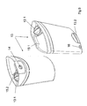
- FIG. 8 an arrangement of a beverage cooling and dispensing device 1 according to the invention and a cleaning container 13 is shown in a perspective view.
- the cleaning container 13 is designed to receive a liquid, in particular a cleaning agent or water, in order to clean or flush all the elements of the beverage cooling and dispensing device 1 that come into contact with the beverage.
- the cleaning container 13 is in this case designed such that, instead of a beverage container 20, it can be connected to the holding piercing device 6 of the beverage cooling and dispensing device 1.
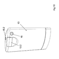
- the cleaning container 13 has an approximately lenticular base surface and is shaped or dimensioned such that it is substantially accurately in the curved portion 7.1 of the housing 7 of the beverage cooling and dispensing device 1 can be introduced.
- Fixing means 15.1, 15.2 are provided for fixing the cleaning container 13 to the beverage cooling and dispensing device 1, wherein the fixing means 15.1 is provided for engagement with the first holding elements 6.1 and the second fixing means 15.2 for engagement with the second holding element 6.2.
- the first fixing means 15.1 is in this case designed to engage behind the first retaining element 6.1 and has an arcuate contour adapted to the first retaining element 6.1.
- the second fixing means 15.2 represents a recess on the upper side of the cleaning container 13, into which the second holding element 6.2 can be brought into engagement.
- the introduction of the cleaning container 13 in the holding piercing device 6 takes place here as well as the introduction of a beverage container 20 via a pivoting movement, wherein first the first fixing means 15.1 is brought into engagement with the first holding element 6.1 and then in a pivoting movement the top of the cleaning container 13 to the second Holding element 6.2 is brought up until the second fixing 15.2 engages in the second holding element 6.2.
- the cleaning container 13 is brought into liquid-tight connection with the piercing device 2 at the same time by the described pivoting movement.
- a first connection element 14 is provided on the cleaning container 13, in which the piercing device 2 is at least partially insertable and thereby produces a liquid-tight connection to just this.
- the first connection element 14 in this case has a valve function, which prevents leakage of a liquid in the interior of the cleaning container from the first connection element 14 when the cleaning container is not introduced into the holding piercing device 6.
- the valve function is canceled, so that the cleaning or rinsing liquid can escape from the cleaning container 13 via the piercing device 2.
- the cleaning container 13 further has a filling opening 13.1, which can be closed in a liquid-tight manner by means of a lid or plug.
- the lid is to be fastened by means of a screw connection to the filling opening 13.1.
- a handle 13.2 is provided, by means of which the cleaning container is easier to handle by the user.
- the cleaning container 13 has a second connection element 16, by means of which the cleaning container 13 can be connected to an external pressure or water supply.
- the second connection element 16, like the first connection element 14, has a valve function, whereby the cleaning vessel 13 can be externally filled with water or pressurized by the second connection element 16, without water or a pressure present in the cleaning vessel 13 over the second Connection element 16 can escape from inside to outside.
- the pressure can be built up via the existing compressed gas device 5.
- compressed gas is supplied from the compressed gas cartridge 5.1 to the cleaning container via the pressurized gas supply pipe 2.2 of the piercing device 2, while the liquid present in the cleaning container 13 is flushed through the line system of the beverage cooling and tapping device 1.
- the dispensing device 4 is open, in this case the entire line system located between the piercing device 2 and the dispensing device 4, including the throughflow cooler 10, is cleaned and / or rinsed.
- FIG. 11 is connected to the connected to the holding and piercing device 6 cleaning tank 13 to the second connection element 16 a hose connection with its first free end, wherein the second free end of the hose is connected to an external water supply, such as a faucet.
- the cleaning container 13 in this case preferably already contains the cleaning agent or a water-cleaning agent mixture, wherein upon opening of the faucet, first of all this cleaning agent or the water-cleaning agent mixture is forced through the conduit system of the beverage cooling and tapping device 1. After this has been pushed through the dispensing system, water continues to flow into the cleaning tank 13 and the line system of the beverage cooling and dispensing device 1 is flushed with just this clear tap water.
- a cleaning container 13 can be used without detergent, said first, this cleaning container 13 is filled via the second connection element 16 with water from the external water supply and then due to the water pressure, the line system of the beverage cooling and dispensing device 1 is rinsed with water.
- This pump 17 can in this case be operated both mechanically and by motor.
- the connection of the pump 17 also takes place via a hose on the second connection element 16.
- a cleaning agent located in the cleaning container 13 is pressed by the pressure built up by the pump 17 through the line system and thus first cleaned the line system. After this cleaning process, clear water can be introduced into the cleaning container 13 via the filling opening 13.1.
- the cleaning container 13 is again connected to the beverage cooling and dispensing device 1 via the holding piercing device 6, built by the pump 17 again pressure and thereby pressed the water through the pipe system, thereby being flushed this line system.
- the dispensing device 4 itself can be unscrewed for cleaning purposes of the beverage cooling and dispensing device 1 and thus also be subjected to a manual cleaning process.
Landscapes
- Physics & Mathematics (AREA)
- Thermal Sciences (AREA)
- Chemical & Material Sciences (AREA)
- Chemical Kinetics & Catalysis (AREA)
- Devices For Dispensing Beverages (AREA)
Applications Claiming Priority (2)
| Application Number | Priority Date | Filing Date | Title |
|---|---|---|---|
| DE102009011595 | 2009-03-08 | ||
| DE102009015128A DE102009015128A1 (de) | 2009-03-08 | 2009-03-31 | Getränkekühl- und Zapfgerät |
Publications (2)
| Publication Number | Publication Date |
|---|---|
| EP2228336A2 true EP2228336A2 (fr) | 2010-09-15 |
| EP2228336A3 EP2228336A3 (fr) | 2010-12-15 |
Family
ID=42538663
Family Applications (1)
| Application Number | Title | Priority Date | Filing Date |
|---|---|---|---|
| EP10002258A Withdrawn EP2228336A3 (fr) | 2009-03-08 | 2010-03-05 | Appareil de refroidissement et de tirage de boisson |
Country Status (2)
| Country | Link |
|---|---|
| EP (1) | EP2228336A3 (fr) |
| DE (1) | DE102009015128A1 (fr) |
Cited By (4)
| Publication number | Priority date | Publication date | Assignee | Title |
|---|---|---|---|---|
| WO2011049446A3 (fr) * | 2009-10-20 | 2011-09-01 | Sara Lee/De N.V. | Contenant d'emballage de fluide |
| AT13982U1 (de) * | 2013-07-16 | 2015-02-15 | Helmut Purner | Vorrichtung zum Kühlen eines Getränks |
| CN106887083A (zh) * | 2017-03-07 | 2017-06-23 | 福州洛克机械设备制造有限公司 | 一种气泡持久的饮料直饮机 |
| WO2023021410A3 (fr) * | 2021-08-17 | 2023-04-13 | Polykeg S.R.L. | Distributeur de boisson compact |
Family Cites Families (4)
| Publication number | Priority date | Publication date | Assignee | Title |
|---|---|---|---|---|
| DE3429559A1 (de) * | 1984-08-10 | 1986-02-20 | Gebrüder Mogler GmbH & Co., 7100 Heilbronn | Vorrichtung zum anstechen von mit fluessigkeit gefuellten behaeltern |
| DE19720553C2 (de) * | 1997-05-16 | 1999-07-15 | Kall Schanktechnik Gmbh | Getränkekühl- und -zapfgerät |
| DE202007018384U1 (de) * | 2006-04-07 | 2008-06-12 | Dsi Getränkearmaturen Gmbh | Getränkekühl- und -zapfgerät |
| DE202008004533U1 (de) * | 2008-04-02 | 2008-05-29 | Atrium Enterprises Gmbh | Vorrichtung zum Kühlen und Zapfen von in Behältern, insbesondere Party-Bierfässern, aufgenommenen Getränken |
-
2009
- 2009-03-31 DE DE102009015128A patent/DE102009015128A1/de not_active Withdrawn
-
2010
- 2010-03-05 EP EP10002258A patent/EP2228336A3/fr not_active Withdrawn
Non-Patent Citations (1)
| Title |
|---|
| None |
Cited By (5)
| Publication number | Priority date | Publication date | Assignee | Title |
|---|---|---|---|---|
| WO2011049446A3 (fr) * | 2009-10-20 | 2011-09-01 | Sara Lee/De N.V. | Contenant d'emballage de fluide |
| JP2013508232A (ja) * | 2009-10-20 | 2013-03-07 | コーニンクラケ ダウ エグバート ビー.ブイ. | 流体包装容器 |
| AT13982U1 (de) * | 2013-07-16 | 2015-02-15 | Helmut Purner | Vorrichtung zum Kühlen eines Getränks |
| CN106887083A (zh) * | 2017-03-07 | 2017-06-23 | 福州洛克机械设备制造有限公司 | 一种气泡持久的饮料直饮机 |
| WO2023021410A3 (fr) * | 2021-08-17 | 2023-04-13 | Polykeg S.R.L. | Distributeur de boisson compact |
Also Published As
| Publication number | Publication date |
|---|---|
| DE102009015128A1 (de) | 2010-09-09 |
| EP2228336A3 (fr) | 2010-12-15 |
Similar Documents
| Publication | Publication Date | Title |
|---|---|---|
| EP4304976B1 (fr) | Machine de préparation de boissons comprenant un moyen de verrouillage et un élément de couplage et système de préparation de boissons | |
| DE60107423T3 (de) | Flüssigkeitsentnahmevorrichtung | |
| DE69800615T2 (de) | Vorrichtung zum Abgeben von Flüssigkeiten, insbesondere Getränken | |
| EP3517488A1 (fr) | Distributeur doté d'une fixation de cartouche | |
| EP1878370B1 (fr) | Dispositif de nettoyage | |
| EP1842828A1 (fr) | Appareil de refroidissement et de tirage de boissons | |
| DE3417005C2 (fr) | ||
| WO2001041907A2 (fr) | Appareil gazeificateur | |
| EP2228336A2 (fr) | Appareil de refroidissement et de tirage de boisson | |
| DE102014008876A1 (de) | Kühl- und/oder Gefriergerät | |
| WO2009121332A2 (fr) | Dispositif de refroidissement et de tirage de boissons se présentant dans des contenants, en particulier de tirage au tonneau de bière lors de réceptions | |
| DE19720553A1 (de) | Getränkekühl- und -zapfgerät | |
| WO2006032642A1 (fr) | Appareil frigorifique comportant une evacuation d'eau | |
| WO2010054734A2 (fr) | Récipient pour boisson fabriqué d'une matière thermoplastique en particulier le pet | |
| EP0787099A1 (fr) | Dispositif de mise a l'air libre pour recipient contenant un liquide | |
| DE202007018384U1 (de) | Getränkekühl- und -zapfgerät | |
| EP0295555B1 (fr) | Support creux ouvert vers le haut avec appareil manuel à faire la crème fouettée | |
| DE102017213924A1 (de) | Getränk-Erzeugungsgerät mit einer mit Umgebungsluft beaufschlagbaren Dekompressionskammer, Haushaltskältegerät sowie Verfahren zum Erzeugen eines Getränks | |
| DE102009053672A1 (de) | Flüssigkeitsspendegerät | |
| DE102006005381B4 (de) | Getränkezapfgerät | |
| DE10128620A1 (de) | Sprudelgetränkegerät | |
| EP2193733A1 (fr) | Machine de préparation de boissons ainsi que récipient de lait correspondant | |
| DE1632031A1 (de) | Fluessigkeitsabsperrventil und Gasabscheider fuer Fluessigkeitsleitungen | |
| WO2012062582A2 (fr) | Appareil frigorifique doté d'un distributeur présentant un dispositif de maintien de récipient réglable en hauteur | |
| DE19816429A1 (de) | Vorrichtung zum Begasen einer Flüssigkeit |
Legal Events
| Date | Code | Title | Description |
|---|---|---|---|
| PUAI | Public reference made under article 153(3) epc to a published international application that has entered the european phase |
Free format text: ORIGINAL CODE: 0009012 |
|
| AK | Designated contracting states |
Kind code of ref document: A2 Designated state(s): AT BE BG CH CY CZ DE DK EE ES FI FR GB GR HR HU IE IS IT LI LT LU LV MC MK MT NL NO PL PT RO SE SI SK SM TR |
|
| AX | Request for extension of the european patent |
Extension state: AL BA ME RS |
|
| PUAL | Search report despatched |
Free format text: ORIGINAL CODE: 0009013 |
|
| AK | Designated contracting states |
Kind code of ref document: A3 Designated state(s): AT BE BG CH CY CZ DE DK EE ES FI FR GB GR HR HU IE IS IT LI LT LU LV MC MK MT NL NO PL PT RO SE SI SK SM TR |
|
| AX | Request for extension of the european patent |
Extension state: AL BA ME RS |
|
| STAA | Information on the status of an ep patent application or granted ep patent |
Free format text: STATUS: THE APPLICATION IS DEEMED TO BE WITHDRAWN |
|
| 18D | Application deemed to be withdrawn |
Effective date: 20110616 |