EP4304976B1 - Machine de préparation de boissons comprenant un moyen de verrouillage et un élément de couplage et système de préparation de boissons - Google Patents
Machine de préparation de boissons comprenant un moyen de verrouillage et un élément de couplage et système de préparation de boissons Download PDFInfo
- Publication number
- EP4304976B1 EP4304976B1 EP22714782.4A EP22714782A EP4304976B1 EP 4304976 B1 EP4304976 B1 EP 4304976B1 EP 22714782 A EP22714782 A EP 22714782A EP 4304976 B1 EP4304976 B1 EP 4304976B1
- Authority
- EP
- European Patent Office
- Prior art keywords
- cartridge
- beverage preparation
- beverage
- liquid
- preparation machine
- Prior art date
- Legal status (The legal status is an assumption and is not a legal conclusion. Google has not performed a legal analysis and makes no representation as to the accuracy of the status listed.)
- Active
Links
Images





Classifications
-
- B—PERFORMING OPERATIONS; TRANSPORTING
- B67—OPENING, CLOSING OR CLEANING BOTTLES, JARS OR SIMILAR CONTAINERS; LIQUID HANDLING
- B67D—DISPENSING, DELIVERING OR TRANSFERRING LIQUIDS, NOT OTHERWISE PROVIDED FOR
- B67D1/00—Apparatus or devices for dispensing beverages on draught
- B67D1/0015—Apparatus or devices for dispensing beverages on draught the beverage being prepared by mixing at least two liquid components
- B67D1/0021—Apparatus or devices for dispensing beverages on draught the beverage being prepared by mixing at least two liquid components the components being mixed at the time of dispensing, i.e. post-mix dispensers
-
- B—PERFORMING OPERATIONS; TRANSPORTING
- B67—OPENING, CLOSING OR CLEANING BOTTLES, JARS OR SIMILAR CONTAINERS; LIQUID HANDLING
- B67D—DISPENSING, DELIVERING OR TRANSFERRING LIQUIDS, NOT OTHERWISE PROVIDED FOR
- B67D1/00—Apparatus or devices for dispensing beverages on draught
- B67D1/0042—Details of specific parts of the dispensers
- B67D1/0043—Mixing devices for liquids
- B67D1/0044—Mixing devices for liquids for mixing inside the dispensing nozzle
-
- B—PERFORMING OPERATIONS; TRANSPORTING
- B67—OPENING, CLOSING OR CLEANING BOTTLES, JARS OR SIMILAR CONTAINERS; LIQUID HANDLING
- B67D—DISPENSING, DELIVERING OR TRANSFERRING LIQUIDS, NOT OTHERWISE PROVIDED FOR
- B67D1/00—Apparatus or devices for dispensing beverages on draught
- B67D1/0042—Details of specific parts of the dispensers
- B67D1/0043—Mixing devices for liquids
- B67D1/0044—Mixing devices for liquids for mixing inside the dispensing nozzle
- B67D1/0046—Mixing chambers
-
- B—PERFORMING OPERATIONS; TRANSPORTING
- B67—OPENING, CLOSING OR CLEANING BOTTLES, JARS OR SIMILAR CONTAINERS; LIQUID HANDLING
- B67D—DISPENSING, DELIVERING OR TRANSFERRING LIQUIDS, NOT OTHERWISE PROVIDED FOR
- B67D1/00—Apparatus or devices for dispensing beverages on draught
- B67D1/0042—Details of specific parts of the dispensers
- B67D1/0057—Carbonators
- B67D1/0061—Carbonators with cooling means
- B67D1/0066—Carbonators with cooling means outside the carbonator
-
- B—PERFORMING OPERATIONS; TRANSPORTING
- B67—OPENING, CLOSING OR CLEANING BOTTLES, JARS OR SIMILAR CONTAINERS; LIQUID HANDLING
- B67D—DISPENSING, DELIVERING OR TRANSFERRING LIQUIDS, NOT OTHERWISE PROVIDED FOR
- B67D1/00—Apparatus or devices for dispensing beverages on draught
- B67D1/0042—Details of specific parts of the dispensers
- B67D1/0078—Ingredient cartridges
- B67D1/0079—Ingredient cartridges having their own dispensing means
-
- B—PERFORMING OPERATIONS; TRANSPORTING
- B67—OPENING, CLOSING OR CLEANING BOTTLES, JARS OR SIMILAR CONTAINERS; LIQUID HANDLING
- B67D—DISPENSING, DELIVERING OR TRANSFERRING LIQUIDS, NOT OTHERWISE PROVIDED FOR
- B67D1/00—Apparatus or devices for dispensing beverages on draught
- B67D1/04—Apparatus utilising compressed air or other gas acting directly or indirectly on beverages in storage containers
-
- B—PERFORMING OPERATIONS; TRANSPORTING
- B67—OPENING, CLOSING OR CLEANING BOTTLES, JARS OR SIMILAR CONTAINERS; LIQUID HANDLING
- B67D—DISPENSING, DELIVERING OR TRANSFERRING LIQUIDS, NOT OTHERWISE PROVIDED FOR
- B67D1/00—Apparatus or devices for dispensing beverages on draught
- B67D1/04—Apparatus utilising compressed air or other gas acting directly or indirectly on beverages in storage containers
- B67D1/0412—Apparatus utilising compressed air or other gas acting directly or indirectly on beverages in storage containers the whole dispensing unit being fixed to the container
- B67D1/0418—Apparatus utilising compressed air or other gas acting directly or indirectly on beverages in storage containers the whole dispensing unit being fixed to the container comprising a CO2 cartridge for dispensing and carbonating the beverage
-
- B—PERFORMING OPERATIONS; TRANSPORTING
- B67—OPENING, CLOSING OR CLEANING BOTTLES, JARS OR SIMILAR CONTAINERS; LIQUID HANDLING
- B67D—DISPENSING, DELIVERING OR TRANSFERRING LIQUIDS, NOT OTHERWISE PROVIDED FOR
- B67D1/00—Apparatus or devices for dispensing beverages on draught
- B67D1/08—Details
- B67D1/0801—Details of beverage containers, e.g. casks, kegs
-
- B—PERFORMING OPERATIONS; TRANSPORTING
- B67—OPENING, CLOSING OR CLEANING BOTTLES, JARS OR SIMILAR CONTAINERS; LIQUID HANDLING
- B67D—DISPENSING, DELIVERING OR TRANSFERRING LIQUIDS, NOT OTHERWISE PROVIDED FOR
- B67D1/00—Apparatus or devices for dispensing beverages on draught
- B67D1/08—Details
- B67D1/0801—Details of beverage containers, e.g. casks, kegs
- B67D1/0809—Opening means, e.g. means for assisting the opening
-
- B—PERFORMING OPERATIONS; TRANSPORTING
- B67—OPENING, CLOSING OR CLEANING BOTTLES, JARS OR SIMILAR CONTAINERS; LIQUID HANDLING
- B67D—DISPENSING, DELIVERING OR TRANSFERRING LIQUIDS, NOT OTHERWISE PROVIDED FOR
- B67D1/00—Apparatus or devices for dispensing beverages on draught
- B67D1/08—Details
- B67D1/0888—Means comprising electronic circuitry (e.g. control panels, switching or controlling means)
-
- B—PERFORMING OPERATIONS; TRANSPORTING
- B67—OPENING, CLOSING OR CLEANING BOTTLES, JARS OR SIMILAR CONTAINERS; LIQUID HANDLING
- B67D—DISPENSING, DELIVERING OR TRANSFERRING LIQUIDS, NOT OTHERWISE PROVIDED FOR
- B67D1/00—Apparatus or devices for dispensing beverages on draught
- B67D1/08—Details
- B67D1/0801—Details of beverage containers, e.g. casks, kegs
- B67D2001/0811—Details of beverage containers, e.g. casks, kegs provided with coded information
-
- B—PERFORMING OPERATIONS; TRANSPORTING
- B67—OPENING, CLOSING OR CLEANING BOTTLES, JARS OR SIMILAR CONTAINERS; LIQUID HANDLING
- B67D—DISPENSING, DELIVERING OR TRANSFERRING LIQUIDS, NOT OTHERWISE PROVIDED FOR
- B67D1/00—Apparatus or devices for dispensing beverages on draught
- B67D1/08—Details
- B67D1/0801—Details of beverage containers, e.g. casks, kegs
- B67D2001/0812—Bottles, cartridges or similar containers
- B67D2001/0814—Bottles, cartridges or similar containers for upside down use
-
- B—PERFORMING OPERATIONS; TRANSPORTING
- B67—OPENING, CLOSING OR CLEANING BOTTLES, JARS OR SIMILAR CONTAINERS; LIQUID HANDLING
- B67D—DISPENSING, DELIVERING OR TRANSFERRING LIQUIDS, NOT OTHERWISE PROVIDED FOR
- B67D1/00—Apparatus or devices for dispensing beverages on draught
- B67D1/08—Details
- B67D1/0801—Details of beverage containers, e.g. casks, kegs
- B67D2001/0812—Bottles, cartridges or similar containers
- B67D2001/0814—Bottles, cartridges or similar containers for upside down use
- B67D2001/0817—Bottles, cartridges or similar containers for upside down use with a venting orifice
Definitions
- the invention relates to a beverage preparation machine for preparing a beverage by means of a cartridge system.
- beverage preparation machines are state of the art, for example from EP 2 017 221 A1 and WO 96/36556 A1 , are generally known and are used to produce beverages from pre-portioned cartridges.
- the production of beverages with such beverage preparation machines is extremely convenient for the user, as they only have to insert a cartridge into the beverage preparation machine and initiate a start-up procedure.
- the beverage preparation machine also known as a dispenser, then produces the beverage fully automatically, i.e. in particular the, preferably liquid, beverage substance is mixed with a predetermined amount of liquid, in particular cold and carbonated water, and dispensed into a drinking vessel.
- mixed drinks in particular can be produced much more easily, quickly and with less effort for the user.
- the user can choose from a variety of different cartridges with different beverage substances, so that they can produce different beverages as desired.
- the object of the present invention was therefore to provide a beverage preparation machine that meets these requirements.
- it should enable leak-free beverage production without recontamination of components of the beverage preparation machine.
- the beverage preparation machine should simultaneously offer a high level of operating convenience and be cost-effective to implement.
- the dispensing is achieved with a beverage preparation machine according to claim 1.
- the present invention relates to a beverage preparation machine, in particular a dispenser, for preparing a beverage by means of a cartridge system consisting of a cartridge containing a beverage substance in a reservoir, and a cartridge receptacle connected to the cartridge, which cartridge receptacle has at least one liquid supply opening, a mixing chamber, and a beverage outlet.
- the cartridge has a cavity as a reservoir in which the beverage substance is located.
- This substrate is preferably liquid and in particular a concentrate and is mixed with a liquid, in particular water, to produce a beverage and then collected in a container, preferably a drinking vessel, in particular a glass and/or a cup, which particularly preferably stands on a support of the dispenser arranged below the cartridge holder in a storage area.
- the storage area comprises in particular a liquid collection device.
- This liquid collection device serves, for example, to collect residual liquid that drips from the beverage outlet and/or the liquid outlet, or if a user does not place a container or drinking vessel in the storage area in time before starting beverage preparation, or if it is not positioned correctly, or if it is removed before preparation is complete.
- the beverage substance preferably comprises liquid pre-mix ingredients for soft drinks, such as caffeinated, carbonated, fruit-based, and/or sugar-containing lemonades and/or juices, beer (mixed) drinks, or other alcoholic or non-alcoholic (mixed) drinks.
- the cartridge preferably has a cartridge opening, which is particularly preferably closed by a sealing element, for example a sealing film, and is thereby separated from the mixing chamber of the cartridge receptacle.
- the cartridge receptacle is preferably firmly, in particular rotationally fixed, connected to the cartridge in a connecting region.
- the beverage preparation machine comprises a cartridge holder, in particular one with a balcony-like design, wherein the cartridge system can be inserted into the cartridge holder.
- Balcony-like preferably means that the cartridge holder protrudes laterally from a housing of the beverage preparation machine and has a substantially horizontal extension.
- the position of the cartridge holder is preferably arranged at a height from a support surface of the beverage preparation machine that corresponds to 20-90% of the total height of the beverage preparation machine, particularly preferably 40-80%, very particularly preferably 50-70%, and in particular substantially 60%.
- the cartridge holder is provided so as to be at least partially height-adjustable.
- the beverage preparation machine comprises a housing in which at least some of the components are fully or partially enclosed.
- the cartridge holder particularly preferably protrudes from this housing.
- the beverage preparation machine further comprises a liquid reservoir and a liquid conditioning system for conditioning a liquid from the liquid reservoir.
- the liquid is preferably water.
- the liquid reservoir is particularly preferably a liquid tank, which is very particularly preferably at least partially arranged in the housing of the beverage preparation machine. Partially means in particular that, for example, the liquid tank is arranged between a base surface and/or a lid of the housing, but an outer wall of the liquid tank is an outer wall of the beverage preparation machine.
- the beverage preparation machine comprises a connection to an external liquid supply network, for example a public water network.
- the beverage preparation machine particularly preferably comprises a liquid conditioning means, in particular a filter device, which is very particularly preferably arranged in the liquid tank, so that the liquid from the liquid tank must flow through the filter device before leaving the same.
- the liquid conditioning system withdraws liquid from the liquid reservoir and conditions it. In the present case, this preferably includes tempering, in particular cooling, and carbonation, i.e., the addition of carbon dioxide to the liquid.
- tempering can easily also include heating the liquid, i.e., generally tempering the liquid to a predetermined temperature, in addition to or as an alternative to cooling.
- the liquid conditioning system makes the conditioned, in particular cooled and carbonated, liquid available to the cartridge system via a coupling element, where it is mixed with the beverage substance in the mixing chamber.
- the beverage preparation machine in particular the liquid conditioning system, comprises at least one pump for pumping the liquid.
- the pump is preferably an oscillating armature pump, but diaphragm pumps and/or rotary pumps can also be used alternatively or additionally.
- the beverage preparation machine comprises at least a first and a second pump, which are preferably connected in parallel.
- the pumps are each operated in alternative phases of a wave-like activation.
- the beverage preparation machine in particular the liquid conditioning system, comprises at least one flow measuring device, which is particularly preferably connected to the control device in order to provide the measured values thereto.
- the control device is particularly intended to use these measured values, in particular, to control the pump.
- a flow measuring device is provided upstream of each pump.
- the liquid conditioning system preferably comprises a compression refrigeration machine, an absorption refrigeration machine and/or a thermoelectric and/or thermoacoustic refrigeration machine.
- a compression refrigeration machine is particularly preferably used in the beverage preparation machine according to the invention.
- Such a compression refrigeration machine comprises at least one Heat exchanger, a compressor, a condenser, and a throttle, in particular a capillary tube and/or an expansion valve.
- the beverage preparation machine comprises a heat engine.
- the heat exchanger is an inline heat exchanger. This means, in particular, that the heat exchanger is integrated into the liquid path, e.g., formed around a liquid line. In this way, the installation space of the beverage preparation machine is advantageously used efficiently.
- the liquid conditioning system includes a carbon dioxide source, a dosing device, and a mixing device.
- a carbon dioxide source Commercially available carbon dioxide cartridges or cylinders are particularly suitable as the carbon dioxide source.
- the beverage preparation machine can also have connection options to an external carbon dioxide source.
- the liquid conditioning system further comprises at least one compensator for reducing the pressure of the carbonated liquid.
- This advantageously achieves a reliable and controlled dispensing of the liquid, so that the carbonated liquid, in particular, does not splash when exiting the beverage preparation machine.
- a predetermined liquid pressure can be set by means of the compensator.
- the compensator is preferably provided in a controllable manner for this purpose.
- the compensator is particularly preferably adjusted at the factory, i.e. during manufacture of the beverage preparation machine; alternatively or additionally, the compensator can be adjusted by a user and/or the control device.
- the quality of the produced beverage can thereby advantageously be increased.
- such a compensator comprises a substantially conically shaped line section in which a longitudinally displaceable conical insert is arranged.
- Such a compensator is an inline compensator, i.e., one integrated into the fluid line.
- the pressure upstream of the compensator is preferably 6-14 bar, particularly preferably 8-12 bar, especially 10 bar, and downstream of the compensator, the pressure most preferably essentially corresponds to the ambient pressure, i.e., approximately 1 bar.
- the beverage preparation machine comprises a coupling element for selectively coupling the liquid conditioning system to the liquid supply opening of the cartridge receptacle.
- the coupling element can thus selectively couple to the cartridge system and, for this purpose, comprises at least one liquid line.
- the beverage preparation machine comprises a control device for controlling the beverage preparation machine, in particular at least some of the aforementioned components, such as the pump, the liquid conditioning system, and/or the coupling element.
- the control device initiates the beverage preparation and, in particular, also terminates it, for example, by stopping the liquid supply.
- the cartridge holder comprises at least one locking means designed to reversibly lock the cartridge system in the cartridge holder, wherein the locking means can be reversibly transferred from an unlocked position to a locked position, wherein the locking means interacts with the cartridge system in a form-fitting and/or force-fitting manner in the locked position.
- the locking means is then actuated and subsequently locks the cartridge system in the cartridge holder. This means that a user cannot remove the cartridge system from the beverage preparation machine without first transferring the locking means to the unlocked position. This particularly advantageously ensures that no ongoing liquid dispensing can take place without a cartridge system being properly inserted into the cartridge holder.
- the coupling element can be transferred from a retracted position into an extended position, wherein in the extended position a, in particular tight, fluid connection is provided between the liquid supply opening of the cartridge receptacle and the liquid line of the coupling element.
- the coupling element is thus provided to be movable, in particular relative to the cartridge system inserted in the cartridge holder, wherein in the extended position a coupling with the cartridge system, in particular the cartridge receptacle, takes place.
- the cartridge holder has a recess, in particular a centrally arranged recess, into which the cartridge system, in particular the cartridge receptacle, can be at least partially inserted.
- the cartridge holder is therefore preferably essentially toroidal.
- the recess is particularly preferably designed to taper downwards so that the cartridge system is securely held in the recess but cannot slip downwards out of the cartridge holder.
- the recess has an essentially circular cross-section in a horizontal plane, in particular the same cross-section as the cartridge receptacle. "Essential" here means that deviations from the circular shape can occur in certain regions.
- the cartridge holder and/or the cartridge receptacle are preferably flat in the region intended for coupling to the coupling element.
- a simpler, tight coupling is enabled, as this is easier to achieve between flat surfaces, and on the other hand, correct orientation between the cartridge system, in particular the cartridge holder, and the beverage preparation machine is ensured, which in turn ensures a reliable, liquid-tight coupling between the cartridge holder and the coupling element.
- the locking means is designed to be rotatable about an axis, in particular a horizontal axis.
- the locking means is an elongated element which is rotatable at one end, for example a lower end, about the axis, in particular a horizontal axis. This enables particularly simple and reliable movement between the unlocked and locked positions, since the upper, movable end can travel a sufficiently large distance to securely lock the cartridge system inserted into the recess.
- the cartridge holder has several, preferably at least three, locking means, which are particularly preferably arranged around the circumference of the recess, in particular This advantageously ensures that the cartridge system is sufficiently securely locked in the cartridge holder in every case.
- the locking means distributed along the circumference of the recess can advantageously compensate for any incorrect positioning of the cartridge system.
- the at least one locking means is at least partially hook-shaped, wherein the hook-shaped portion is intended to cooperate in a locking manner with a portion of the cartridge system, in particular a flange of the cartridge.
- the cartridge and/or the cartridge receptacle therefore preferably has at least one laterally, in particular horizontally, projecting region behind which the locking means can engage. Since the recess is preferably tapered and the locking means according to this embodiment prevent upward movement, the cartridge system is advantageously securely secured in the cartridge holder despite the simple design of the locking means.
- the hook shape also enables a particularly advantageous dissipation of forces, even if a user pulls upwards on the cartridge system with a certain force.
- the at least one locking means comprises at least one predetermined breaking point in order to avoid damage to the cartridge holder and/or the beverage preparation machine in the previously explained case.
- the at least one locking means is preloaded toward the unlocked position, in particular by a spring.
- a spring is a particularly simple, proven, and reliable way to ensure that the locking means is in the unlocked position, so that a cartridge system can be easily inserted into the cartridge holder.
- the beverage preparation machine in particular the cartridge holder, has an operating element, in particular a hand lever, wherein the operating element is adjustable between a first position and a second position, wherein in the first position of the operating element the locking means is in the unlocked position and in the second position of the operating element the locking means is in the locked position, wherein the operating element is configured such that when adjusted from the first position to the second position the locking means is adjusted from the unlocked position to the locked position.
- the hand lever preferably projects horizontally laterally from the cartridge holder.
- the operating element is rotatable about a vertical axis, which runs in particular centrally through the recess of the cartridge holder, preferably in an angular range of 10 to 180 degrees, particularly preferably in an angular range of 40-120 degrees, most particularly preferably in an angular range of approximately 90 degrees.
- a user can thus advantageously bring about the transfer of the locking means into the locked position, or after the beverage preparation into the unlocked position.
- the person skilled in the art will understand that the above-mentioned vertical axis coincides in particular with a longitudinal axis of the cartridge system when the cartridge system is properly inserted into the cartridge holder.
- the cartridge holder preferably comprises an indicator element to show the user that the locked and/or unlocked position has been correctly reached.
- This can, for example, be a marking, whereby the user must bring the operating element into alignment with the marking.
- the indicator element is designed to emit an acoustic and/or visual signal to indicate correct locking and/or unlocking.
- the design of the control element as a pivoting lever is a particularly simple and intuitive option for the user. In particular, the different angle positions allow the user to immediately recognize whether the locking device is in the unlocked or locked position.
- a user signals to the control device that a cartridge system is inserted simply by means of an operating element, such as a physical and/or virtual button, and that the locking means is automatically moved into the locked position, in particular via a motorized drive.
- an operating element such as a physical and/or virtual button
- the operating element is connected, in particular in one piece, to a slotted guide, wherein the slotted guide is designed to transfer the locking means from the unlocked to the locked position upon adjustment, in particular a rotation about the vertical axis.
- the slotted guide is designed in one piece with the operating element, the complexity of the beverage preparation machine is also advantageously reduced, since fewer components are present.
- the slotted guide preferably has several guides, in particular identical to one another, so that preferably all locking means are moved simultaneously.
- the coupling element is preloaded toward the extended position, in particular by a spring.
- a spring This ensures, in a particularly simple manner, that the coupling element automatically assumes a coupling position, i.e., the extended position, unless a component of the beverage preparation machine explicitly prevents this.
- the force exerted by the spring also advantageously ensures a certain contact pressure between the liquid supply opening and the coupling element, thus increasing the tightness of the connection.
- the operating element is connected, in particular in one piece, to a slotted guide, wherein the slotted guide is designed to transfer the coupling element from the extended position to the retracted position upon adjustment, in particular a rotation about the vertical axis.
- the coupling element has a guide means which is designed to functionally interact with the slotted guide.
- the guide means is a projection, in particular designed in one piece with the coupling element, wherein the projection very particularly preferably bears against the slotted guide with a contact surface.
- the slotted guide which interacts with the coupling element can be designed in one piece with the slotted guide which interacts with the locking means or can be manufactured separately and optionally connected to the slotted guide.
- the slotted guides are different sections of a common slotted guide.
- the transfer of the locking means from the locked to the unlocked position is simultaneously linked with the transfer of the coupling element from the extended to the retracted position.
- the cartridge system can preferably be removed from the cartridge holder.
- the movements of the coupling element and the locking means are effected differently. Since the locking means is preferably pretensioned toward the unlocked position, the guide rail clears a path for the locking means, while the spring tension effects the movement of the locking means. With the coupling element, this occurs in particular in the opposite manner.
- the spring tension here preferably effects a pretension toward the extended position. while the link guide actively moves the coupling element towards the retracted position.
- the beverage preparation machine comprises a compressed air source, wherein the compressed air source is configured to supply compressed air to the cartridge system, in particular to a compressed air supply opening of the cartridge receptacle, wherein the coupling element is further configured for selective coupling between the compressed air source and the compressed air supply opening of the cartridge receptacle, wherein the coupling element has a compressed air line.
- the compressed air is used to transfer the beverage substance from the reservoir of the cartridge into the mixing chamber of the cartridge receptacle.
- the compressed air is introduced into the reservoir through a compressed air line, which on the one hand prevents the formation of a negative pressure and on the other hand preferably actively expels the beverage substance by the compressed air. This advantageously ensures that the entire beverage substance is transferred from the cartridge and advantageously shortens the beverage preparation time.
- a particularly tight fluid connection is established between the compressed air supply opening of the cartridge holder and the compressed air line of the coupling element.
- This tight fluid connection is preferably established simultaneously with the tight fluid connection between the fluid supply opening and the fluid line of the coupling element.
- the coupling element has a sealing means at least in an area intended for contact with the cartridge receptacle, wherein the sealing means comprises an at least partially elastic material, in particular an elastic plastic material.
- the sealing means is provided as a coating.
- the sealing means is sprayed onto the coupling element or applied using an in-mold process.
- the sealing means is made of a food-safe material.
- the sealing means contains silicone.
- the cartridge holder has at least one stop means, which preferably interacts with a slotted guide, in particular the slotted guide explained above, in such a way that the first position and/or the second position are defined as end positions.
- the stop means is an element that is firmly connected, in particular integrally, to the cartridge holder and which interacts positively and/or non-positively with a guide in the slotted guide in the first and/or second position.
- the stop means is designed in the shape of a pin. This ensures that the cartridge holder is not damaged by the operating element and/or the slotted guide being moved beyond the first and/or second position.
- the cartridge holder comprises a position detection means for detecting at least one position of the operating element and/or the slotted guide.
- the position detection means is particularly preferably a position switch or limit switch.
- the position detection means comprises a light barrier and/or a proximity switch.
- the position detection means is arranged such that it detects when the operating lever has reached the second position and/or when the locking means has reached the locked position.
- the position detection means or a further position detection means is configured such that it detects the extended position of the coupling means. This advantageously prevents
- the fluid line and preferably the compressed air line of the coupling element are rigid lines and are provided in particular as one piece in the coupling element.
- the coupling element is preferably designed to be movable, at least one sectionally flexible line must be arranged between the fluid conditioning system and the coupling element and/or between the compressed air source and the coupling element in order to compensate for the movement.
- the provision of rigid lines in the coupling element ensures reliable operation, since Constant orientation of the lines relative to the cartridge holder and therefore also to the cartridge system arranged therein is ensured. Furthermore, complex maintenance of the movable coupling element is eliminated.
- the beverage preparation machine in particular the control device, is configured such that beverage preparation, in particular a liquid supply and/or a compressed air supply through the coupling element, is only possible when the operating element is in the second position and/or the locking means is in the locked position.
- the control device is functionally connected to the position detection means such that beverage preparation can only be initiated when the position detection means has detected that the locking means has reached the locked position and/or that the operating element has reached the second position. This ensures that incorrect operation of the beverage preparation machine is excluded.
- a further subject matter of the present invention is a beverage preparation system with a beverage preparation machine according to the invention and a cartridge system, wherein the cartridge system for beverage preparation can be inserted into the cartridge holder of the beverage preparation machine, wherein the cartridge system comprises a cartridge comprising a reservoir filled with a beverage substance, and a cartridge receptacle connectable to the cartridge in a connection area, wherein the cartridge has a cartridge opening, wherein the cartridge opening is closed with a sealing element, in particular a sealing film, wherein the sealing element closes the reservoir in a fluid-tight manner with respect to the cartridge receptacle, wherein the cartridge receptacle has a mixing chamber connectable to the reservoir and a liquid supply opening opening into the mixing chamber for coupling to the liquid line of the coupling element, so that a liquid can be introduced into the mixing chamber, wherein the cartridge receptacle has a cartridge unloading device for transferring the beverage substance from the reservoir into the mixing chamber, wherein the cartridge receptacle has a Beverage
- the beverage preparation system according to the invention is particularly flexible and hygienic since no recontamination of parts of the beverage preparation machine occurs and liquid withdrawal after premature removal of the cartridge system is excluded since the locking means holds the cartridge system securely in the cartridge holder and preferably the control device prevents liquid withdrawal in the unlocked position of the locking means.
- the cartridge and/or the cartridge receptacle is preferably made of plastic, in particular by an (in-)molding and/or blow-molding process.
- the cartridge has a side wall which, for example, has a round, rectangular, square, conical or oval cross-section.
- a base is usually provided, in particular in one piece.
- the side wall and the base region define a cavity which forms the reservoir in which a beverage substance, in particular in liquid form, is provided.
- a connecting region is provided with which the cartridge is connected to the cartridge receptacle.
- the cartridge can be made at least partially of glass.
- an intermediate piece is preferably provided between the cartridge receptacle and the cartridge.
- Such an intermediate piece functions, in particular, as an adapter.
- conventional, commercially available bottles made of glass or other materials can also be used in the cartridge system.
- the cartridge comprises a cartridge neck having at least one flange, in particular at least two flanges spaced apart from one another.
- the at least one flange particularly preferably protrudes from the connecting region and is at an angle, most preferably at a right angle, from a Wall area of the connection area.
- the flange is in particular aligned horizontally.
- the flange is made of solid material, i.e. not hollow.
- the flange is injection-molded and/or made in one piece with the cartridge, in particular the side wall of the cartridge and/or the cartridge neck.
- the cartridge receptacle preferably essentially establishes the connection to the cartridge holder
- the cartridge can be designed flexibly.
- the cartridge can have different diameters and/or different axial lengths in order to accommodate different volumes of beverage substance.
- the beverage substance is preferably in liquid form, in particular as a syrup and/or a beverage concentrate.
- the cartridge holder it is also conceivable for the cartridge holder to at least partially comprise support means for the cartridges, for example in the form of a stand-up collar.
- the cartridge receptacle can be permanently connected to the cartridge or can be a replacement part that is removed from the cartridge after use and connected to a new cartridge.
- the cartridge receptacle is connected to the cartridge in a form-fitting and/or force-fitting manner, in particular by clipping.
- the flange on the cartridge interacts sealingly with the cartridge receptacle.
- the circumference of the flange can, for example, engage in a groove in the cartridge receptacle.
- This flange/groove connection can also serve as a force-fitting connection to prevent the cartridge from shifting relative to the cartridge receptacle during beverage or food production, which could cause the connection between the cartridge and the cartridge receptacle to leak.
- the locking means cooperates with the at least one flange in a locking manner.
- a fastening means is provided in the side wall region of the cartridge and/or in the region of the cartridge neck.
- the at least one locking means cooperates with the fastening means in a locking manner, alternatively or in addition to the flange.
- the fastening means can, for example, be a groove into which the locking means engages.
- the cartridge has a cartridge opening, wherein the cartridge opening is closed with a sealing element, in particular a sealing film, wherein the sealing element seals the reservoir fluid-tightly with respect to the cartridge receptacle.
- the sealing element is attached to the at least one flange, in particular sealed thereto.
- the sealing film particularly preferably comprises a single- or multi-layer membrane. It is crucial that the sealing element, on the one hand, seals the reservoir fluid-tightly closes, so that even in the preferred arrangement according to the invention, in which the cartridge system is inserted into the cartridge holder with the cartridge opening facing downwards, the beverage substance cannot leave the reservoir when the sealing element is closed.
- the sealing element must be able to be opened locally and easily by the cartridge unloading device, so that the beverage substance can be transferred, in particular, quickly and completely into the mixing chamber of the cartridge holder.
- the beverage preparation machine comprises an identification detector for reading a product identification code on the cartridge and/or the cartridge receptacle, wherein the identification detector is preferably arranged above and/or behind the cartridge holder, in particular in the housing of the beverage preparation machine.
- the identification detector is preferably arranged above and/or behind the cartridge holder, in particular in the housing of the beverage preparation machine.
- a disc that is transparent at least to the radiation used and in particular also in the optical range is arranged in front of the identification detector.
- the product identification code is preferably embedded in a barcode, an RFID code, a QR code, a data matrix code, a color code, a hologram code, or the like. This advantageously enables automatic reading of the product identification code.
- the identification detector comprises, in particular, an optical sensor, such as a CCD camera, which automatically reads the barcode, QR code, or data matrix code when the cartridge system is inserted into the beverage preparation machine.
- the identification detector comprises a transmitting and receiving antenna for automatically reading the RFID codes.
- the product identification code it would be conceivable for the product identification code to be embedded in other automatically readable computer chips.
- QR code encompasses, in particular, any data matrix code.
- QR code and data matrix code are used synonymously.
- the product identification code to comprise a barcode, a dot code, a binary code, a Morse code, a Braille code (braille), or the like.
- the code can also be embedded in a three-dimensional structure, such as a relief.
- the product identification code encompasses, in particular, the so-called product identification number, in particular a Universal Product Code (UPC), a European Article Number (EAN), a GS1 code, a Global Trade Item Number (GTIN), or the like. This eliminates the need to introduce a new code system.
- the product identification code complies with the GS1 standard.
- the product identification code is preferably printed, glued and/or embedded directly onto the cartridge and/or cartridge holder. The marking is applied to the cartridge, e.g., by (laser) engraving, punching, or directly during cartridge production.
- the cartridge it would also be conceivable for the cartridge to be at least partially covered with a coating, such as a sleeve, on which the product identification code is arranged.
- a coating such as a sleeve
- the coating can also be glued or welded to the cartridge and/or the cartridge holder.
- the coating or sleeve could be made of a plastic film, textile, or paper.
- the cartridge unloading device comprises a mandrel guide and a piercing mandrel mounted displaceably within the mandrel guide, in particular in one direction.
- the piercing mandrel can be displaced by an actuator element of the beverage preparation machine between a retracted position, in which the piercing mandrel is spaced from the sealing element, and an extended position, in which the piercing mandrel pierces the sealing element and extends into the reservoir.
- a cartridge unloading device designed in this way is particularly advantageous because the piercing mandrel enables a targeted and simple opening of the sealing element and thus a precisely controllable transfer of the beverage substance from the reservoir into the mixing chamber.
- the beverage preparation machine comprises a drive, in particular a motorized drive, for the actuator element.
- the drive is coupled to the operating element, in particular the hand lever.
- the drive is arranged in the housing of the beverage preparation machine and functionally connected to the actuator element via a deflection mechanism.
- the actuator element of the beverage preparation machine is preferably controllable by the control device.
- the cartridge receptacle in particular the cartridge unloading device, comprises a compressed air supply opening for coupling with the compressed air line of the coupling element, a compressed air outlet and a compressed air line which extends from the compressed air supply opening to the Compressed air outlet extends, wherein the coupling element is designed to introduce compressed air from the compressed air source of the beverage preparation machine through the compressed air supply opening into the compressed air line, wherein the compressed air line is preferably integrated into the piercing mandrel, wherein the cartridge unloading device is particularly preferably designed such that, in the extended position of the piercing mandrel, the beverage substance can be transferred from the reservoir into the mixing chamber by the compressed air.
- the beverage preparation machine comprises a compressed air source.
- the compressed air source provides the compressed air which - in particular only in the extended position of the piercing mandrel - is introduced through the compressed air line of the piercing mandrel and via the compressed air outlet into the reservoir, thereby assisting the transfer of the beverage substance from the reservoir into the mixing chamber.
- the compressed air supply opening of the cartridge receptacle can be brought into fluid communication with a compressed air line of the beverage preparation machine.
- the beverage preparation machine is configured such that compressed air is provided, in particular immediately after a fluid-tight connection has been established between the compressed air supply opening of the cartridge receptacle and the compressed air line of the coupling element. Since the compressed air line is thus pressurized, in particular immediately after a connection has been established, it is advantageously prevented that beverage substance can enter the beverage preparation machine through the compressed air line, thereby preventing cross-contamination and further improving the hygiene of the beverage preparation machine.
- the piercing mandrel preferably has at least one, preferably several indentations and/or protrusions, in particular channels, on its outer circumference, which serve as a drain for the beverage substance.
- the number and size of the indentations and/or protrusions preferably depends on the viscosity of the beverage substance.
- the outer wall of the piercing mandrel is therefore preferably provided with at least one side channel for guiding the beverage substance in the direction of the mixing chamber in the extended position, when the sealing element is pierced.
- the substrate can then flow past the sealing element in the direction of the mixing chamber through the side channel formed laterally on the piercing mandrel and in particular extending substantially vertically.
- the at least one side channel is designed in particular in the form of a groove open on one side. It is conceivable that in particular the cross section of the The side channel is adapted to the viscosity of the beverage substance, so that the at least one side channel controls or limits the flow of the beverage substance toward the mixing chamber. At high viscosity, multiple side channels and/or side channels with a larger cross-section are used, while at lower viscosity, fewer side channels or side channels with a smaller cross-section are provided.
- the method according to the invention offers the same advantages as the beverage preparation machine according to the invention and the beverage preparation system according to the invention, i.e. in particular a simple, hygienic and reliable beverage preparation in which incorrect operation and/or contamination due to unintentionally escaping liquid are excluded.
- the steps of transferring the beverage substance from the reservoir of the cartridge into the mixing chamber of the cartridge receptacle and of introducing a liquid into the mixing chamber of the cartridge receptacle occur essentially simultaneously.
- the chronological sequence of the steps can be controlled by the control device, in particular taking into account product information read by the identification detector.
- the time, speed, degree of carbonation, and/or temperature of the introduced liquid can be controlled depending on the beverage substance, in particular its viscosity. This is particularly advantageous for highly viscous beverage substances, e.g., syrup.
- the step of transferring the beverage substance from the reservoir of the cartridge into the mixing chamber of the cartridge receptacle comprises actuating the cartridge unloading device, in particular by transferring the piercing spike from the retracted position to the extended position, thereby causing the sealing element to be perforated.
- an actuator element of the beverage preparation machine is particularly preferably activated, which moves the piercing spike into the extended position.
- the actuator element is activated by a drive, in particular one controlled and/or motorized by the control device.
- the actuator element is connected directly or indirectly to the operating element, for example via a trigger mechanism.
- a user can actuate and/or release the actuator element by moving the hand lever to the second position, so that the control device receives the command to activate or actuate the actuator element by actuating another control element, such as a pushbutton switch, a physical and/or virtual button. This further simplifies the beverage preparation process.
- the step of transferring the locking means from the unlocked position to the locked position comprises transferring the operating element from the first position to the second position
- the step of transferring the coupling element from the retracted position to the extended position comprises transferring the operating element from the first position to the second position.
- the user can thus lock the cartridge system in the cartridge holder in a simple and comprehensible manner, or, in particular, unlock it again after the beverage has been prepared.
- the liquid is tempered, in particular cooled, and/or carbonated by the liquid conditioning system before being introduced into the mixing chamber.
- a product identification code is read by the code detector before, during, or after inserting the cartridge system into the cartridge holder and/or feeding compressed air into the cartridge and/or introducing the liquid into the mixing chamber.
- the read product identification code is preferably evaluated by the control device, wherein the feeding of compressed air and/or liquid particularly preferably only occurs if the product identification code can be verified by the control device.
- the properties of the liquid and in particular the temporal progression of the volume flow, the total volume, the pressure, the feed pauses, the temperature and/or the degree of carbonation of the fed liquid are controlled depending on the (verified) product identification code.
- the properties of the fed compressed air and in particular the temporal progression of the volume flow, the total volume, the feed pauses and/or the pressure of the fed compressed air are also controlled depending on the (verified) product identification code.
- the ratio between the volume flow of the liquid and the volume flow of the compressed air is also controlled depending on the (verified) product identification code.
- FIG 1 a beverage preparation machine 1 according to an exemplary embodiment of the present invention is shown.
- Figure 1 in particular, one possible appearance of the beverage preparation machine 1.
- the beverage preparation machine 1 comprises a housing 2 in which most of the functional components, such as a liquid conditioning system, a coupling element 21, a power connection, a control device implemented, for example, on a circuit board, and the like, are arranged.
- the beverage preparation machine 1 comprises a power connection (not shown here) to an external power supply network and/or an internal energy storage device, for example, an accumulator sufficiently dimensioned for multiple beverage preparation processes.
- the beverage preparation machine 1 here comprises a liquid reservoir 3, which is preferably designed as a water tank, as shown.
- the liquid reservoir 3 can be arranged externally, as shown, and connected to the housing 2 only via a base region. However, it is equally possible for the liquid reservoir 3 to be arranged entirely or partially within the housing 2.
- the liquid reservoir 3 can be removed from the housing 2 for filling and/or can be filled via a cover access in the housing.
- Such a liquid reservoir 3 can additionally comprise means for liquid treatment.
- such a means consists of a filter element, in particular for adjusting the lime content of the liquid.
- control elements 6 are arranged in the upper area of the housing 2. These are designed, for example, as push-button switches, but can take any desired form, such as a touchscreen with virtual buttons, physical knobs, virtual or physical rotary switches, etc. Using these additional control elements 6, a user can, for example, start or initiate a beverage preparation process and preferably also cancel it. Furthermore, control elements 6 can be provided, for example, for selecting a liquid volume and/or a carbonation level.
- a cartridge holder 4 is arranged laterally protruding from the housing 2. This cartridge holder 4 is the central location for beverage preparation.
- a cartridge system consisting of a cartridge 10 and a cartridge receptacle 14 connected to the cartridge can be arranged in the cartridge holder 4, which has a central recess for this purpose.
- the recess is preferably provided so that it tapers downwards so that a cartridge system can be inserted into the cartridge holder 4 from above, but cannot slide out of it downwards.
- the cartridge holder 4 is approximately circular in shape, but only a recess that fits the cartridge receptacle 14 is crucial; the external shape of the cartridge holder 4 and its dimensions, however, are essentially freely selectable.
- the balcony-like shape shown here is generally preferred because the resulting delicate and free-floating impression is particularly aesthetically pleasing.
- the recess cooperates at least partially with the cartridge receptacle 14 in a form-fitting manner.
- This form-fitting engagement is particularly preferably further supported by the cartridge holder 4 having an opening for a beverage outlet 15 of the cartridge receptacle 14 at its lower end, so that the cartridge receptacle 14 can only be correctly inserted into the cartridge holder 4 in one orientation such that the cartridge system can be locked in the cartridge holder 4.
- a storage area 7 which here comprises a storage grid and preferably a liquid collection device.
- a container for example a drinking vessel such as a mug, cup, or glass, can be placed on the storage grid. If the user positions the drinking vessel too late in the storage area or misaligns it, or if dripping occurs, the beverage and/or liquid can pass through the storage grid into the liquid collection device arranged below and be subsequently removed.
- the cartridge holder 4 is provided here at approximately 60% of the total height of the beverage preparation machine 1.
- the cartridge holder 4 can also be provided higher, for example at a height between 60% and 100%, preferably between 70% and 90%, and in particular at approximately 80% of the total height, or lower, for example at a height between 20% and 60%, preferably between 30% and 50%, and in particular at approximately 40% of the total height of the beverage preparation machine.
- the cartridge holder 4 is provided with an adjustable height. In this way, the cartridge holder 4 can be adapted to the height of the respective drinking vessel, so that the beverage does not fall into the drinking vessel from too great a height. In this way, splashing of the beverage can be prevented.
- an operating element in the form of a hand lever 5 is provided on the cartridge holder.
- a user can pivot the hand lever 5 about a vertical axis running centrally through the recess between a first position and a second position. As will be explained in more detail below, this serves to lock the cartridge system in the cartridge holder 4, so that the cartridge system cannot be removed from the cartridge holder 4.
- the cartridge holder 4 and in particular the hand lever 5 are coupled to the control device of the beverage preparation machine 1 in such a way that the start of the beverage preparation is not possible when the hand lever 5 is in the first position, which corresponds to an unlocked position.
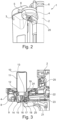
- FIG 2 A perspective detailed view of a beverage preparation machine 1 according to an exemplary embodiment of the present invention is shown. The illustrated embodiment is similar to that described in connection with Figure 1 discussed embodiment, so that reference is generally made to the relevant explanations.
- the beverage preparation machine 1 is shown. Visible on the left is the liquid reservoir 3, in which, in this case, a filter cartridge can be seen. Furthermore, additional operating elements 6 are indicated on the upper edge of the housing 2. The focus here is on the cartridge holder 4 and the hand lever 5.
- the hand lever 5 is formed integrally with a circumferential collar of the cartridge holder 4 and, in this case, for example, From its first position, it can be pivoted to the left by approximately 90° to the right into a second position.
- the first position corresponds to an open position in which a user can insert a cartridge system consisting of a cartridge 10 and the associated cartridge receptacle 14.
- the second position corresponds to a locked position in which the cartridge system is locked in the cartridge holder 4, so that it can no longer be removed (without being damaged) from the cartridge holder 4.
- the manner in which this locking is achieved is described below, particularly with regard to the Figures 6-11 explained in more detail.
- the aforementioned angular range of approximately 90°, within which the hand lever 5 can be pivoted, is exemplary.
- An angular range of 60°, 120°, or 180° is also conceivable.
- an angular range of approximately 90°, in particular between 60° and 120° is particularly advantageous because in this case the position of the hand lever 5 is easily and directly recognizable by the user, so that the user can advantageously see at a glance whether a locked or unlocked position is present.
- This can be further reinforced by appropriate markings and/or infographics or symbols on the cartridge holder 4. For example, on the outside of the cartridge holder 4, an unlocked lock is depicted in the area of the first position and a locked lock in the second position.
- An outlet can be seen in the front area on the underside of the cartridge holder 4. This is an optional additional dedicated liquid outlet 9, through which liquid, particularly tempered and/or carbonated, can be dispensed separately and/or in addition to the beverage.
- an actuator element 20 is indicated. This is preferably designed as a rocker arm and, as shown, is located largely within the housing of the cartridge holder 4 and the beverage preparation machine 1. One end of this Actuator element 20, which when activated actuates a cartridge unloading device of the cartridge holder 14, is visible here.
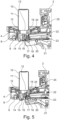
- FIGS 3 to 5 are schematic sectional views of successive steps of a method according to an exemplary embodiment of the present invention. Only a section of the beverage preparation machine 1 with the cartridge holder 4 is shown.
- the beverage preparation machine 1 can be designed according to the embodiments explained in connection with the preceding figures, for which reason reference is made to the relevant explanations.
- Figure 3 The beverage preparation system and its components are explained in detail below.
- an optional identifier detector 25 is additionally provided in the present case. This is arranged, for example, behind a pane transparent to the radiation used in the housing 2 of the beverage preparation machine 1 and is aligned such that it can read a product identification code arranged on an outer side of the cartridge 10 and/or the cartridge receptacle 14.
- a product identification code arranged on an outer side of the cartridge 10 and/or the cartridge receptacle 14.
- the control device and/or the identifier detector 25 can comprise a communication module for communicating with an external resource, such as a remote server.
- an external resource such as a remote server.
- the control device controls the beverage preparation parameters based on the product identification code determined by the identifier detector 25.
- Such parameters include, for example, parameters relating to the liquid, such as temperature, degree of carbonation, volume and/or velocity of the liquid flow; parameters relating to the compressed air, such as pressure, volume and/or velocity of the compressed air; or dynamic parameters, such as the timing of liquid and/or compressed air supply or the progression of the aforementioned parameters.
- a beverage preparation cycle may include pauses in the liquid and/or compressed air supply and/or varying pressures and/or volumes over time.
- the cross-section clearly shows the dedicated liquid outlet 9, which is essentially semi-toroidal and extends around the recess.
- the actuator element 20, which according to the embodiment shown here is also designed as a rocker arm tiltable about a horizontal axis, can be connected in the beverage preparation machine 1 to a drive, in particular a motorized drive, which is preferably controllable by the control device.
- the beverage preparation machine 1 further comprises components not shown here for the sake of clarity.
- the beverage preparation machine 1 comprises a liquid conditioning system. This is arranged downstream of the liquid reservoir 3 and upstream of the cartridge holder 4. Such a liquid conditioning system is intended to condition the liquid before it is fed into the cartridge system, in particular to temper and/or carbonate it.
- the liquid conditioning system comprises, for example, among other things, at least one (hydraulic) pump for transporting the liquid. It is also possible in principle to use multiple pumps, for example connected in parallel, if the required pumping capacity cannot be easily achieved with a single pump.
- a flow meter is preferably assigned to the at least one pump. The flow meter provides the control device with the required measured values to control the pump.
- the pump preferably pumps the liquid to a temperature control device. In the present case, this is, for example, a compression refrigeration machine that cools the liquid, in particular water, to a temperature perceived as pleasant for drinking, for example, approximately 3-8°C.
- Such a compression refrigeration machine comprises, in a known manner, at least one heat exchanger, a compressor, a condenser, and a throttle, in particular a capillary tube and/or an expansion valve.
- the heat exchanger is preferably designed as an inline heat exchanger, i.e., the liquid is cooled while it flows through the liquid line.
- the beverage preparation machine 1 may also comprise a container in which the water is tempered.
- the beverage preparation machine 1 in the present case comprises a carbonation system, which preferably comprises, among other things, a carbon dioxide source, in particular in the form of commercially available metal cylinders. These are interchangeably inserted and connected into the beverage preparation machine 1. Since such cylinders are under high pressure, the carbonation system comprises a pressure reduction device downstream of the carbon dioxide source and Downstream of this, a dosing device. The dosing device is preferably controllable by the control device and/or by a user and serves to determine the desired degree of carbonation for the liquid.
- the carbonation system preferably comprises a mixing device downstream of the dosing device, which is particularly designed as an inline mixing device, i.e., the carbonation of the liquid occurs while it flows through the liquid line and, in particular, not in a stationary state.
- the mixing device is preferably arranged downstream of the liquid tempering system, so that already tempered, in particular cooled, liquid is carbonated in the mixing device.
- the beverage preparation machine 1 further comprises a compressed air source.
- a compressed air source In its simplest form, this can consist of ambient air being drawn in from outside the beverage preparation machine 1, which is then pressurized by a suitable pump.
- the (air) pump can also be considered part of the compressed air source.
- the beverage preparation machine 1 comprises a connection to an external compressed air supply network, which provides compressed air to the beverage preparation machine 1. Compressed air is supplied from the compressed air source to the cartridge system via the coupling element 21.
- the beverage preparation machine 1 further comprises, in particular downstream of the mixing device and upstream of the coupling element 21, at least one compensator for reducing the pressure of the carbonated liquid, and particularly preferably at least one valve.
- a valve is particularly preferred in conjunction with the additional liquid outlet 9.
- a predetermined liquid pressure can be set by means of the compensator.
- the compensator is preferably provided in a controllable manner for this purpose.
- the compensator is adjusted at the factory, i.e., during manufacture of the beverage preparation machine; alternatively or additionally, the compensator can be adjusted by a user and/or the control device.
- the cartridge system consists of a cartridge 10, which comprises a side wall and a base region, which together define a cavity serving as a reservoir 11 for a beverage substance, in particular a liquid one.
- the side wall can have essentially any cross-section. However, a square or a (circular) round cross-section is preferred.
- the cartridge 10 further comprises a cartridge neck that encloses a cartridge opening.
- the cartridge opening is sealed in an airtight and/or liquid-tight manner by a sealing element 13, preferably a sealing film, for example a single- or multi-layer membrane made of a plastic material and/or a metallic material such as aluminum or an aluminum alloy.
- the beverage substance is thus enclosed in the reservoir up to an opening of the sealing element 13.
- the cartridge 10 is preferably manufactured from a plastic material, for example by injection molding or injection molding or by a blow molding technique. The same applies particularly to the cartridge holder 14.
- the cartridge neck has a smaller diameter than the side wall, thus representing a constriction.
- the cartridge neck and/or the cartridge opening comprises at least one flange 12, particularly preferably two vertically spaced flanges.
- the sealing element 13 is connected to at least one flange 12, in particular by a material bond.
- the sealing element 13 can be sealed to a flange 12 circumferentially surrounding the cartridge opening.
- a connecting area is provided, via which the cartridge 10 is connected to a cartridge receptacle 14, which is in particular essentially cap-shaped, in a form-fitting, force-fitting and/or material-fitting and in particular in a rotationally fixed manner.
- the cartridge receptacle 14 is clipped, for example, to the at least one circumferential flange 12.
- An embodiment is shown here purely by way of example, according to which the cartridge 10 has two essentially identical, but vertically spaced-apart flanges 12.
- the cartridge receptacle 14 is connected, in particular, to the lower flange 12 in the drawing in a force-locking and/or form-locking manner.
- the second flange 12 cooperates in a locking manner with a locking means 8 in a manner to be explained below.
- the cartridge receptacle 14 has a mixing chamber and at least one liquid supply opening 19, wherein the liquid supplied via the liquid supply opening 19 by the beverage preparation machine 1, in particular a carbonated and/or cooled liquid, mixes in the mixing chamber with the beverage substance from the reservoir 11.
- the mixing creates a (mixed or blended) beverage, which is then dispensed through a beverage outlet 15 of the cartridge receptacle 14 directly into a drinking vessel arranged below.
- the beverage does not touch any components of the beverage preparation machine 1, thereby avoiding any cross-contamination in a particularly hygienic manner.
- the cartridge receptacle 14 also has a dedicated gas outlet to discharge gas released during mixing from the cartridge receptacle 14.
- the cartridge receptacle 14 further comprises at least one cartridge unloading device.
- This is embodied, for example, as a piercing mandrel 16 mounted in a mandrel guide for vertical displacement.
- the piercing mandrel 16 is preferably formed as a plastic part and particularly preferably as a plastic injection-molded part.
- the piercing mandrel 16 can be moved from a retracted position to an extended position by an actuator element 20 of the beverage preparation machine 1. In the extended position, it pierces the sealing element 13 and thus ensures a fluidic connection between the reservoir 11 and the mixing chamber.
- Beverage preparation machine 1 and in particular the control device thus determines the time of beverage preparation since, on the one hand, it initiates the supply of liquid into the mixing chamber and, on the other hand, activates the actuator element which actuates the cartridge unloading device and thus ensures that the beverage substance is transferred from the reservoir 11 into the mixing chamber.
- the piercing mandrel 16 has recesses on its outer side, in particular channel-like recesses, which extend substantially vertically according to the orientation shown here.
- the beverage substance can flow from the reservoir 11 into the mixing chamber via these recesses as soon as the sealing element 13 is pierced.
- the channel-like recesses are designed in the form of grooves open on one side, wherein the cross-section and/or the number of recesses is preferably adapted to the viscosity of the beverage substance.
- the beverage preparation machine 1 comprises, according to the invention, a coupling element 21 which can be transferred from a retracted position, which is shown here, into an extended position (cf. Figure 4 ).
- the coupling element 21 establishes a fluid-tight coupling between the liquid conditioning system of the beverage preparation machine 1 and the liquid supply opening 19 of the cartridge receptacle 14.
- the fact that the coupling element 21 is spaced apart from the cartridge receptacle 14 in the retracted position ensures that the coupling element 21 is securely connected to the cartridge receptacle 14 when inserting the The cartridge system is not damaged. Furthermore, moving it into the extended position ensures a fluid-tight coupling.
- the coupling element 21 is a rigid element which internally comprises a liquid line 22, in particular a one-piece liquid line, and a compressed air line 23, in particular a one-piece liquid line.
- these lines are arranged at an angle to one another, with the compressed air line 23 running essentially horizontally.
- the liquid line 22 runs slightly downwards in the direction of flow, as this facilitates the complete discharge of the liquid and thus advantageously prevents dripping from the beverage preparation machine 1.
- the precise arrangement of the liquid line 22 and/or the compressed air line 23 depends primarily on the arrangement of the fluid-carrying components in the beverage preparation machine 1.
- a line which is at least partially flexible is provided in order to compensate for the movement of the coupling element 21 between the retracted position and the extended position.
- the three locking means 8 are preferably of identical design and arranged uniformly along the circumference of the recess.
- the upper end of the locking means 8 is of a hook-like, in particular rounded, design.
- At least one locking means 8 is provided according to the invention, but a greater number, such as three here, improves the locking, so that even greater forces can be absorbed. This prevents the user from removing the cartridge system from the cartridge holder during beverage preparation, i.e. when the locking means 8 is in the locked position.
- the locking means 8 have at least one predetermined breaking point, so that accidental premature removal of the cartridge system is prevented, but forced removal is possible to avoid damage to the beverage preparation machine 1.
- the slotted guide makes it easy for all locking means 8 to be actuated simultaneously.
- the locking means 8 are preferably biased outwardly at their lower end, i.e., toward the unlocked position, by a spring 28. This means that as soon as the user moves the hand lever 5 back toward the first position, the locking means 8 slide back into the unlocked position along the guide rail 27 by the spring 28.
- the coupling element 21 is also pretensioned into the extended position by means of a spring 28', wherein the coupling element 21 is guided by a further slotted guide 27', which is most preferably not identical to the slotted guide 27 assigned to the locking means 8, but in particular is designed as a single piece therewith.
- both the locking means 8 are in the locked position and the coupling element 21 is in the extended position.
- the liquid line 22 of the coupling element 21 is aligned with the liquid supply opening 19 of the cartridge holder 14 and is connected to it in a liquid-tight manner by the sealing means 24.
- the compressed air line 23 of the coupling element 21 is aligned with the compressed air supply opening 18 of the cartridge holder 14 and is connected to it in an airtight manner by the sealing means 24.
- compressed air is already present in this position.
- the piercing mandrel 16 is in the retracted position, the compressed air does not yet enter the compressed air line 17 and consequently does not exit the compressed air outlet opening of the piercing mandrel 16.
- the beverage preparation machine 1 is ready for beverage preparation in the position shown here.
- the control device has preferably previously activated a drive that actuates the actuator element 20. This pivots it about the fixed horizontal tilt axis, so that an end, in particular designed as a plunger, contacts the piercing mandrel 16 and displaces it upwards in the mandrel guide into the extended position. On the way to the extended position, the piercing mandrel 16 pierces the sealing element 13, and the beverage substance begins to flow between the piercing mandrel 16 and the sealing element 13, in particular via the above-mentioned, optional channels of the piercing mandrel 16, into the mixing chamber.
- the compressed air line 17 integrated into the piercing mandrel 16 is aligned with the compressed air supply opening 18 or the compressed air line of the cartridge holder 14 arranged there between.
- the compressed air is now introduced through the piercing mandrel 16 into the reservoir 11 and, on the one hand, prevents the development of a negative pressure and, at the same time, supports the transfer of the, under certain circumstances, highly viscous, beverage substance from the reservoir 11 into the mixing chamber.
- the flow of the beverage substance into the mixing chamber can therefore be accelerated and/or specifically controlled by the compressed air.
- the cartridge system is now empty and can be removed from the cartridge holder 4.
- the beverage preparation machine 1 is now ready for a new beverage preparation cycle.
- Figure 6 1 shows a perspective detailed view of a cartridge holder 4 according to an exemplary embodiment of the present invention.
- a horizontal section is shown.
- the embodiment shown here essentially corresponds to the previously explained embodiments, for which reason reference is made to the relevant explanations.
- the hand lever 5 can be seen, which is integrally connected to a collar-like element which forms the upper end of the cartridge holder 4.
- the slotted guide 27 is also formed integrally with this element and thus with the hand lever 5. This simplifies the structure, since only one element is required and no deflection mechanism is needed to transfer the movement from the hand lever 5 to the slotted guide 27.
- FIG 7 A schematic top view of a cartridge holder 4 according to an exemplary embodiment of the present invention is shown.
- the embodiment shown here essentially corresponds to the previously explained embodiments, for which reason reference is made to the relevant explanations.
- the top view of the Figure 6 shown detail. It is clearly visible how the slotted guide 27 is designed as one piece with the hand lever 5. Guides for one or more similar stop means 26 are provided on the outside, while the guide for the locking means 8 is arranged on the inside. As can be seen from the illustration, the guides have a certain dead zone, i.e. a distance over which there is no change in the position of the locking means 8. This is helpful so that even small movements and/or incorrect positioning of the hand lever 5 do not block the cartridge holder 4 from blocking the insertion or removal of a cartridge system.
- a cartridge 10 of an inserted cartridge system is visible.
- This has a side wall with a substantially circular cross-section, although the side wall is flattened on one side, here the right side in the illustration.
- This asymmetry is preferably also present in the cartridge receptacle 14 and in particular also in the inner wall of the recess of the cartridge holder 4.
- This provides a guide that ensures that the cartridge system, and in particular the liquid supply opening 19 and the compressed air supply opening 18 of the cartridge receptacle 14, are correctly oriented after insertion. This ensures a successful and reproducible coupling with the coupling element 21.
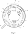
- FIGS 8 and 9 are sectional views in different horizontal planes of a cartridge holder 4 in the first position.
- Figures 10 and 11 Corresponding sectional views are shown in the different horizontal planes of the cartridge holder 4 in the second position.
- the illustrated embodiment of the cartridge holder 4 corresponds to the Figures 8-11 essentially the previously explained embodiments, which is why reference is made to the relevant explanations.
- FIG 8 a schematic plan view of a cartridge holder 4 with an operating element, here a hand lever 5, in the first position according to an exemplary embodiment of the present invention is shown.
- the sectional plane shown here is particularly lower than that shown in FIG. Figure 9 .
- the contours of the slotted guide 27 which interact with the three locking means 8 are shown here. Even if this is not apparent from the present drawing, the slotted guide 27 is integrally connected to the hand lever 5 in the manner described above.
- the hand lever 5 is here in the first position. According to the embodiment shown here, the first position is reached with respect to the orientation shown at an angular position of the hand lever 5 of approximately 220°. This is advantageous because, on the one hand, the hand lever 5 is easily accessible for a user who is usually positioned in front of the beverage preparation machine 1 and, on the other hand, the first position is clearly visible.
- the coupling element 21 is shown. This has a projection 30 on its upper side, which interacts with a contour of a further slotted guide 27' and thus holds the coupling element 21 in the retracted position against the spring force of a spring 28' arranged in particular on the underside of the coupling element 21. It is particularly advantageous if the slotted guide 27' for the coupling element 21 is formed integrally with the slotted guide 27 for the locking means 8. This is also provided according to the embodiment shown here. In the right-hand part of the figure, it can be seen that the contours of the slotted guides 27, 27' converge.
- a limit switch 29 is provided in the right-hand area of the cartridge holder 4, which determines the relative position of the slotted guides 27, 27' and/or the hand lever 5 via the associated collar-like element. This relative position can then be transmitted to the control device. This determined position can, for example, be used to ensure that the control device only enables beverage preparation when the limit switch 29 detects that the hand lever 5 is in the second position.
- the sealing means 24 can be clearly seen, which is designed here as an elastic coating of the coupling element 21.
- the sealing means 24 preferably comprises a hygienically safe material approved for food preparation
- the drawing also shows the projection in the drawing plane of the previously explained stop means 26.
- the locking means 8 also border on a stop of the contour of the slotted guide 27.
- a stop is formed by the stop means 26 and a corresponding guide in the slotted guide 27.
- FIG. 9 The representation of the Figure 9 now essentially corresponds to that of Figure 8 , but with a different, horizontal, cutting plane.
- the cutting plane chosen here lies above that of Figure 8
- the projection 30 of the coupling element 21 interacts with a contour of a further slotted guide 27', which, however, can be formed integrally with the slotted guide 27.
- the projection does not interact with the guide which forms a stop for the stop means 26, even if this is Figure 9
- This illustration clearly shows the one-piece design of hand lever 5 and guide rail 27. This is particularly advantageous because only one moving component is required.
- Figure 10 now shows the cartridge holder 4 of the Figures 8 and 9 in the second position, which corresponds to the locked position of the locking means 8.
- the locking means 8 have been moved into the locked position by the contour of the slotted guide 27, counter to the spring force exerted by the spring 28 at their base, where they are connected to the cartridge holder 4 so as to be pivotable about a horizontal axis of rotation.
- the contour of the further slotted guide 27' has cleared the path for the coupling element 21, so that the latter is moved into the extended position by the spring 28 arranged on the underside, in particular a spiral spring, and thereby couples with the cartridge holder 14.
- Figure 10 Both the coupling element 21 and the locking means 8 are still shown in the unlocked or retracted position. However, those skilled in the art will understand which position is actually assumed. However, the chosen representation advantageously allows the adjustment path of the coupling element 21 and the locking means 8 to be recognized.
- FIG 11 is like in Figure 10 a schematic plan view of a cartridge holder 4 with the hand lever 5 in the second position according to an exemplary embodiment of the present invention.
- the representation of the coupling element 21 and the locking means 8 is decoupled from the position of the The person skilled in the art will understand that the coupling element 21 in the second position is actually moved further radially into the center of the recess and the rear surfaces of the upper region of the hook-like locking means 8 rest against the inside of the slotted guide 27.
- the stop means 26 forms a stop for the slotted guide 27, so that the second position is defined as the end position. This can be detected accordingly by the limit switch 29.
- FIG 12 A perspective detailed view of a cartridge holder 4 according to an exemplary embodiment of the present invention is shown.
- the illustrated embodiment essentially corresponds to the previously described embodiments, so reference is made to the preceding explanations.
- an outer housing of the cartridge holder 4 is shown here, as shown, for example, in Figure 2 shown, not shown.
- the structure of the collar-like element connected to the hand lever 5 can be seen, which serves as the upper end of the cartridge holder 4 and is pivotable relative to the latter between the first and second positions, which are defined as end positions by the at least one stop means 26.
- the hand lever, on the one hand, and the slotted guides 27, 27' and the guide for the stop means 26, on the other hand, are formed integrally with this element. It can be seen from the drawing that the element is designed differently at different height levels, with, for example, the level of the slotted guide 27 interacting with the locking means 8 being higher than the level of the slotted guide 27' interacting with the coupling element 21.
- the design of the coupling element 21 is clearly visible, including the projection 30 formed on the upper side. Furthermore, it can be seen that the spring 28' is arranged around the compressed air line 23, which is particularly space-saving.
- the compressed air line 23 and the liquid line 22 are formed integrally in the coupling element 21, wherein the coupling element 21 is made, for example, from a plastic material.
- the sealing means 24, which is arranged at the tip of the coupling element 21, is clearly visible. In the areas of the coupling element 21 intended for contact with the cartridge receptacle 14, the sealing means 24 and/or the coupling element 21 are rounded in order to achieve a flexible and secure coupling.
- the embodiment of the coupling element 21 shown here remotely resembles a gun barrel.
- Figure 13 is a schematic plan view of a cartridge holder 4 according to an exemplary embodiment of the present invention, wherein the representation in particular of a plan view and a cross section in a horizontal cross section of the embodiment from Figure 12 In particular, the embodiment shown essentially corresponds to that of Figure 10 , which is why reference is made to the relevant explanations, although here the coupling element 21 is shown in the correct, extended position.
Landscapes
- Chemical & Material Sciences (AREA)
- Chemical Kinetics & Catalysis (AREA)
- Apparatus For Making Beverages (AREA)
- Devices For Dispensing Beverages (AREA)
Claims (15)
- Machine de préparation de boissons (1), en particulier distributeur, servant à la préparation d'une boisson à l'aide d'un système à cartouche constitué d'une cartouche (10), qui présente une substance de boisson dans un réservoir (11), et d'un logement de cartouche (14) relié à la cartouche (10), lequel comprend au moins une ouverture d'amenée de liquide (19), une chambre de mélange et une sortie de boisson (15), la machine de préparation de boissons (1) comprenant un support de cartouche (4) réalisé en particulier en forme de balcon, le système à cartouche pouvant être inséré dans le support de cartouche (4), la machine de préparation de boissons (1) présentant un réservoir de liquide (3), un système de conditionnement de liquide servant au conditionnement d'un liquide provenant du réservoir de liquide (3), un élément de couplage (21) servant au couplage sélectif entre le système de conditionnement de liquide et l'ouverture d'amenée de liquide (19) du logement de cartouche (14) et un dispositif de commande servant à la commande de la machine de préparation de boissons (1), l'élément de couplage (21) présentant au moins une conduite de liquide (22), caractérisée en ce que le support de cartouche (4) présente au moins un moyen de verrouillage (8), lequel est prévu pour verrouiller le système à cartouche de manière réversible dans le support de cartouche (4), le moyen de verrouillage (8) pouvant être transféré de manière réversible d'une position déverrouillée à une position verrouillée, le moyen de verrouillage (8), dans la position verrouillée, coopérant par complémentarité de formes et/ou par force avec le système à cartouche.
- Machine de préparation de boissons (1) selon la revendication 1, caractérisée en ce que l'élément de couplage (21) peut être transféré d'une position rentrée à une position sortie, une liaison fluidique, en particulier étanche, entre l'ouverture d'amenée de liquide (19) du logement de cartouche (14) et la conduite de liquide (22) de l'élément de couplage (21) étant présente dans la position sortie.
- Machine de préparation de boissons (1) selon l'une des revendications précédentes, caractérisée en ce que le moyen de verrouillage (8) est réalisé de manière rotative autour d'un axe disposé en particulier horizontalement.
- Machine de préparation de boissons (1) selon l'une des revendications précédentes, caractérisée en ce que l'au moins un moyen de verrouillage (8) est réalisé au moins dans certaines parties en forme de crochet, la partie en forme de crochet étant prévue pour coopérer de manière verrouillée avec une partie du système à cartouche, en particulier un rebord (12) de la cartouche (10).
- Machine de préparation de boissons (1) selon l'une des revendications précédentes, caractérisée en ce que la machine de préparation de boissons (1), en particulier le support de cartouche (4), présente un élément de commande, en particulier un levier à main (5), l'élément de commande étant déplaçable entre une première position et une deuxième position, le moyen de verrouillage (8) étant dans la position déverrouillée dans la première position de l'élément de commande et le moyen de verrouillage (8) étant dans la position déverrouillée dans la deuxième position de l'élément de commande, l'élément de commande étant configuré de telle sorte que, lors du déplacement de la première position à la deuxième position, le moyen de verrouillage (8) est transféré de la position déverrouillée à la position verrouillée.
- Machine de préparation de boissons (1) selon la revendication 5, caractérisée en ce que l'élément de commande est rotatif autour d'un axe vertical qui s'étend en particulier centralement à travers l'évidement du support de cartouche (4), de préférence dans une plage angulaire de 10 à 180 degrés, de manière particulièrement préférée dans une plage angulaire de 40 à 120 degrés, mieux encore dans une plage angulaire de 90 degrés approximativement.
- Machine de préparation de boissons (1) selon l'une des revendications 5 ou 6, caractérisée en ce que l'élément de commande est relié, en particulier d'un seul tenant, à un guide à coulisse (27), le guide à coulisse (27) étant réalisé pour transférer le moyen de verrouillage (8) de la position déverrouillée à la position verrouillée lors d'un déplacement, en particulier une rotation, autour de l'axe vertical.
- Machine de préparation de boissons (1) selon l'une des revendications précédentes, caractérisée en ce que la machine de préparation de boissons (1) comprend une source d'air comprimé, la source d'air comprimé étant conçue pour acheminer de l'air comprimé au système à cartouche, en particulier à une ouverture d'amenée d'air comprimé (18) du logement de cartouche (14), l'élément de couplage (21) étant en outre conçu pour le couplage sélectif entre la source d'air comprimé et l'ouverture d'amenée d'air comprimé (18) du logement de cartouche (14), l'élément de couplage (21) présentant une conduite d'air comprimé (23).
- Machine de préparation de boissons (1) selon au moins l'une des revendications 2 et 8, caractérisée en ce que, dans la position sortie, une liaison fluidique, en particulier étanche, entre l'ouverture d'amenée d'air comprimé (18) du logement de cartouche (14) et la conduite d'air comprimé (23) de l'élément de couplage (21) est présente, en particulier l'élément de couplage (21) présentant, au moins dans une région prévue pour la mise en contact avec le logement de cartouche (14), un moyen d'étanchéité (24), le moyen d'étanchéité (24) comprenant une matière au moins partiellement élastique, en particulier une matière synthétique élastique.
- Machine de préparation de boissons (1) selon l'une des revendications 5 à 7, caractérisée en ce que la machine de préparation de boissons (1), en particulier le dispositif de commande, est configuré(e) de telle sorte qu'une préparation de boissons, en particulier une amenée de liquide et/ou une amenée d'air comprimé à travers l'élément de couplage (21), n'est possible que lorsque l'élément de commande est dans la deuxième position et/ou que le moyen de verrouillage (8) est dans la position verrouillée.
- Système de préparation de boissons comportant une machine de préparation de boissons (1) selon l'une des revendications précédentes et un système à cartouche, le système à cartouche pouvant être inséré dans le support de cartouche (4) de la machine de préparation de boissons (1) pour la préparation de boissons, le système à cartouche comprenant une cartouche (10) qui comprend un réservoir (11) rempli d'une substance de boisson, et comprenant un logement de cartouche (14) pouvant être relié à la cartouche (10) dans une région de liaison, la cartouche (10) présentant une ouverture de cartouche, l'ouverture de cartouche étant fermée à l'aide d'un élément d'étanchéité (13), en particulier une feuille d'étanchéité, l'élément d'étanchéité (13) fermant le réservoir (11) de manière étanche aux fluides par rapport au logement de cartouche (14), le logement de cartouche (14) présentant une chambre de mélange pouvant être amenée en liaison avec le réservoir (11) et une ouverture d'amenée de liquide (19) débouchant dans la chambre de mélange pour le couplage avec la conduite de liquide (22) de l'élément de couplage (21), de sorte qu'un liquide peut être introduit dans la chambre de mélange, le logement de cartouche (14) présentant un dispositif de purge de cartouche servant au transfert de la substance de boisson du réservoir (11) à la chambre de mélange, le logement de cartouche (14) présentant une sortie de boisson (15) servant à l'évacuation, hors de la chambre de mélange, d'une boisson obtenue par mélange du liquide avec la substance de boisson.
- Système de préparation de boissons selon la revendication 11, caractérisé en ce que le dispositif de purge de cartouche comprend un guide de mandrin et un mandrin de perçage (16) monté de manière coulissante à l'intérieur du guide de mandrin, en particulier dans une direction, le mandrin de perçage (16) pouvant coulisser entre une position rentrée, dans laquelle le mandrin de perçage (16) est espacé d'un élément d'étanchéité (13), et une position sortie, dans laquelle le mandrin de perçage (16) transperce l'élément d'étanchéité (13) et fait saillie jusque dans le réservoir (11), par le biais d'un élément actionneur (20) de la machine de préparation de boissons (1), la machine de préparation de boissons (1) comprenant un entraînement, en particulier motorisé, pour l'élément actionneur (20).
- Système de préparation de boissons selon l'une des revendications 11 ou 12, caractérisé en ce que le logement de cartouche (14), en particulier le dispositif de purge de cartouche, comprend une ouverture d'amenée d'air comprimé (18) servant au couplage avec la conduite d'air comprimé (23) de l'élément de couplage (21), une sortie d'air comprimé et une conduite d'air comprimé (17), laquelle s'étend de l'ouverture d'amenée d'air comprimé (18) à la sortie d'air comprimé, l'élément de couplage (21) étant réalisé pour introduire de l'air comprimé à partir de la source d'air comprimé de la machine de préparation de boissons (1) à travers l'ouverture d'amenée d'air comprimé (18) dans la conduite d'air comprimé (17), la conduite d'air comprimé (17) étant intégrée de préférence dans le mandrin de perçage (16), le dispositif de purge de cartouche étant réalisé de manière particulièrement préférée de telle sorte que, dans la position sortie du mandrin de perçage (16), la substance de boisson peut être transférée hors du réservoir (11) dans la chambre de mélange par l'air comprimé.
- Procédé de préparation d'une boisson à l'aide d'un système de préparation de boissons selon l'une des revendications 11 à 13, caractérisé par les étapes suivantes :- insertion d'un système à cartouche constitué d'une cartouche (10) et d'un logement de cartouche (14) dans le support de cartouche (4),- transfert du moyen de verrouillage (8) de la position déverrouillée à la position verrouillée- transfert de l'élément de couplage (21) de la position rentrée à la position sortie pour produire une liaison entre la conduite de liquide (22) de l'élément de couplage (21) et l'ouverture d'amenée de fluide (19) du logement de cartouche (14) ainsi que pour produire de préférence une liaison entre la conduite d'air comprimé (23) de l'élément de couplage (21) et l'ouverture d'amenée d'air comprimé (18) du logement de cartouche (14),- transfert de la substance de boisson du réservoir (11) de la cartouche (10) à la chambre de mélange du logement de cartouche (14), en particulier par alimentation du réservoir (11) en air comprimé,- introduction d'un liquide dans la chambre de mélange du logement de cartouche (14) à travers l'élément de couplage (21),- évacuation, à travers la sortie de boisson (15), de la boisson produite dans la chambre de mélange par mélange de la substance de boisson avec le liquide.
- Procédé selon la revendication 14, l'étape de transfert de la substance de boisson du réservoir (11) de la cartouche (10) à la chambre de mélange du logement de cartouche (14) comprenant un actionnement du dispositif de purge de cartouche, en particulier par transfert du mandrin de perçage (16) de la position rentrée à la position sortie, de sorte qu'une perforation de l'élément d'étanchéité (13) soit provoquée.
Applications Claiming Priority (2)
| Application Number | Priority Date | Filing Date | Title |
|---|---|---|---|
| DE102021202397 | 2021-03-11 | ||
| PCT/EP2022/056328 WO2022189623A1 (fr) | 2021-03-11 | 2022-03-11 | Machine de préparation de boissons comprenant un moyen de verrouillage et un élément de couplage et système de préparation de boissons |
Publications (3)
| Publication Number | Publication Date |
|---|---|
| EP4304976A1 EP4304976A1 (fr) | 2024-01-17 |
| EP4304976B1 true EP4304976B1 (fr) | 2025-05-07 |
| EP4304976C0 EP4304976C0 (fr) | 2025-05-07 |
Family
ID=81325761
Family Applications (1)
| Application Number | Title | Priority Date | Filing Date |
|---|---|---|---|
| EP22714782.4A Active EP4304976B1 (fr) | 2021-03-11 | 2022-03-11 | Machine de préparation de boissons comprenant un moyen de verrouillage et un élément de couplage et système de préparation de boissons |
Country Status (13)
| Country | Link |
|---|---|
| US (1) | US20240140774A1 (fr) |
| EP (1) | EP4304976B1 (fr) |
| JP (1) | JP2024510592A (fr) |
| KR (1) | KR20230142611A (fr) |
| CN (1) | CN116963992A (fr) |
| AU (1) | AU2022231982B2 (fr) |
| BR (1) | BR112023016339A2 (fr) |
| CA (1) | CA3209752A1 (fr) |
| ES (1) | ES3037337T3 (fr) |
| HU (1) | HUE072038T2 (fr) |
| IL (1) | IL304987A (fr) |
| PL (1) | PL4304976T3 (fr) |
| WO (1) | WO2022189623A1 (fr) |
Families Citing this family (21)
| Publication number | Priority date | Publication date | Assignee | Title |
|---|---|---|---|---|
| US12213617B2 (en) | 2022-05-13 | 2025-02-04 | Sharkninja Operating Llc | Flavored beverage carbonation process |
| US11751585B1 (en) | 2022-05-13 | 2023-09-12 | Sharkninja Operating Llc | Flavored beverage carbonation system |
| US11647860B1 (en) | 2022-05-13 | 2023-05-16 | Sharkninja Operating Llc | Flavored beverage carbonation system |
| US12096880B2 (en) | 2022-05-13 | 2024-09-24 | Sharkninja Operating Llc | Flavorant for beverage carbonation system |
| US12539500B2 (en) | 2022-08-31 | 2026-02-03 | Sharkninja Operating Llc | Additive containers |
| US11634314B1 (en) | 2022-11-17 | 2023-04-25 | Sharkninja Operating Llc | Dosing accuracy |
| US11745996B1 (en) | 2022-11-17 | 2023-09-05 | Sharkninja Operating Llc | Ingredient containers for use with beverage dispensers |
| US11738988B1 (en) | 2022-11-17 | 2023-08-29 | Sharkninja Operating Llc | Ingredient container valve control |
| US12103840B2 (en) | 2022-11-17 | 2024-10-01 | Sharkninja Operating Llc | Ingredient container with sealing valve |
| US12084334B2 (en) | 2022-11-17 | 2024-09-10 | Sharkninja Operating Llc | Ingredient container |
| IT202200018567A1 (it) * | 2022-12-20 | 2024-06-20 | Celli Spa | Macchina per l’erogazione di bevande gassate |
| USD1092208S1 (en) | 2022-12-23 | 2025-09-09 | Sharkninja Operating Llc | Cap of ingredient container |
| USD1091308S1 (en) | 2022-12-23 | 2025-09-02 | Sharkninja Operating Llc | Ingredient container |
| US11871867B1 (en) | 2023-03-22 | 2024-01-16 | Sharkninja Operating Llc | Additive container with bottom cover |
| US12116257B1 (en) | 2023-03-22 | 2024-10-15 | Sharkninja Operating Llc | Adapter for beverage dispenser |
| US11925287B1 (en) | 2023-03-22 | 2024-03-12 | Sharkninja Operating Llc | Additive container with inlet tube |
| US12005408B1 (en) | 2023-04-14 | 2024-06-11 | Sharkninja Operating Llc | Mixing funnel |
| USD1111812S1 (en) | 2023-09-20 | 2026-02-10 | The Cumulus Coffee Company | Pod |
| USD1113343S1 (en) | 2023-09-20 | 2026-02-17 | The Cumulus Coffee Company | Pod |
| USD1113444S1 (en) | 2024-05-14 | 2026-02-17 | The Cumulus Coffee Company | Pod |
| USD1113443S1 (en) | 2024-05-14 | 2026-02-17 | The Cumulus Coffee Company | Pod |
Family Cites Families (11)
| Publication number | Priority date | Publication date | Assignee | Title |
|---|---|---|---|---|
| US5842603A (en) | 1990-06-06 | 1998-12-01 | The Coca-Cola Company | Postmix juice dispenser |
| DE202007018384U1 (de) * | 2006-04-07 | 2008-06-12 | Dsi Getränkearmaturen Gmbh | Getränkekühl- und -zapfgerät |
| EP2017221A1 (fr) * | 2007-07-19 | 2009-01-21 | Nestec, Ltd. | Dispositif de distribution de liquide |
| ATE479626T1 (de) * | 2007-07-19 | 2010-09-15 | Nestec Ltd | Vorrichtung zur abgabe einer flüssigkeit |
| US8746506B2 (en) * | 2011-05-26 | 2014-06-10 | Pepsico, Inc. | Multi-tower modular dispensing system |
| RU2016137526A (ru) * | 2011-08-03 | 2018-12-13 | Кьюриг Грин Маунтин, Инк. | Способ и устройство газирования напитков с использованием картриджа |
| US20140079856A1 (en) * | 2012-06-29 | 2014-03-20 | Darren Hatherell | Beverage Carbonating System and Method for Carbonating a Beverage |
| ES2939370T3 (es) * | 2016-01-12 | 2023-04-21 | Freezio Ag | Sistema de dispensador con soporte para cartucho |
| DK3548404T3 (en) * | 2016-12-01 | 2021-06-21 | Bedford Systems Llc | Container and opening arrangement for beverage production |
| RS62028B1 (sr) * | 2017-06-26 | 2021-07-30 | Freezio Ag | Uređaj za proizvodnju napitka |
| ES2913264T5 (en) * | 2017-11-27 | 2026-04-16 | Freezio Ag | Cartridge receptacle, cartridge system, beverage preparation machine, and method for producing a beverage |
-
2022
- 2022-03-11 IL IL304987A patent/IL304987A/en unknown
- 2022-03-11 US US18/278,265 patent/US20240140774A1/en active Pending
- 2022-03-11 CN CN202280020649.2A patent/CN116963992A/zh active Pending
- 2022-03-11 HU HUE22714782A patent/HUE072038T2/hu unknown
- 2022-03-11 WO PCT/EP2022/056328 patent/WO2022189623A1/fr not_active Ceased
- 2022-03-11 JP JP2023555606A patent/JP2024510592A/ja active Pending
- 2022-03-11 CA CA3209752A patent/CA3209752A1/fr active Pending
- 2022-03-11 EP EP22714782.4A patent/EP4304976B1/fr active Active
- 2022-03-11 ES ES22714782T patent/ES3037337T3/es active Active
- 2022-03-11 PL PL22714782.4T patent/PL4304976T3/pl unknown
- 2022-03-11 BR BR112023016339A patent/BR112023016339A2/pt unknown
- 2022-03-11 AU AU2022231982A patent/AU2022231982B2/en active Active
- 2022-03-11 KR KR1020237030930A patent/KR20230142611A/ko not_active Ceased
Also Published As
| Publication number | Publication date |
|---|---|
| AU2022231982A1 (en) | 2023-08-31 |
| EP4304976A1 (fr) | 2024-01-17 |
| ES3037337T3 (en) | 2025-10-01 |
| JP2024510592A (ja) | 2024-03-08 |
| AU2022231982B2 (en) | 2025-06-05 |
| US20240140774A1 (en) | 2024-05-02 |
| BR112023016339A2 (pt) | 2023-10-03 |
| CA3209752A1 (fr) | 2022-09-15 |
| IL304987A (en) | 2023-10-01 |
| KR20230142611A (ko) | 2023-10-11 |
| CN116963992A (zh) | 2023-10-27 |
| PL4304976T3 (pl) | 2025-09-01 |
| WO2022189623A1 (fr) | 2022-09-15 |
| HUE072038T2 (hu) | 2025-10-28 |
| EP4304976C0 (fr) | 2025-05-07 |
Similar Documents
| Publication | Publication Date | Title |
|---|---|---|
| EP4304976B1 (fr) | Machine de préparation de boissons comprenant un moyen de verrouillage et un élément de couplage et système de préparation de boissons | |
| EP3674255B1 (fr) | Distributeur doté d'une fixation de cartouche | |
| EP4304975B1 (fr) | Machine de préparation de boisson pourvue d'un mécanisme d'entraînement et d'un système de préparation de boisson | |
| EP3716823B2 (fr) | Logement de cartouche, système de cartouche, machine de préparation de boissons et procédé de préparation d'une boisson | |
| EP4274452B1 (fr) | Dispositif de réception pour cartouche, système de cartouche, système de préparation de boissons et procédé de préparation d'une boisson | |
| DE69832211T2 (de) | Getränkespender | |
| DE102007001609A1 (de) | Vorrichtung zur Bereitstellung eines inbesondere kohlensäurehaltigen Getränks | |
| EP2816003A1 (fr) | Distributeur et récipient | |
| WO2025099239A1 (fr) | Pointe de perforation, support de cartouche, système de préparation d'une boisson, procédé de préparation d'une boisson et utilisation d'une pointe de perforation |
Legal Events
| Date | Code | Title | Description |
|---|---|---|---|
| STAA | Information on the status of an ep patent application or granted ep patent |
Free format text: STATUS: UNKNOWN |
|
| STAA | Information on the status of an ep patent application or granted ep patent |
Free format text: STATUS: THE INTERNATIONAL PUBLICATION HAS BEEN MADE |
|
| PUAI | Public reference made under article 153(3) epc to a published international application that has entered the european phase |
Free format text: ORIGINAL CODE: 0009012 |
|
| STAA | Information on the status of an ep patent application or granted ep patent |
Free format text: STATUS: REQUEST FOR EXAMINATION WAS MADE |
|
| 17P | Request for examination filed |
Effective date: 20231011 |
|
| AK | Designated contracting states |
Kind code of ref document: A1 Designated state(s): AL AT BE BG CH CY CZ DE DK EE ES FI FR GB GR HR HU IE IS IT LI LT LU LV MC MK MT NL NO PL PT RO RS SE SI SK SM TR |
|
| DAV | Request for validation of the european patent (deleted) | ||
| DAX | Request for extension of the european patent (deleted) | ||
| GRAP | Despatch of communication of intention to grant a patent |
Free format text: ORIGINAL CODE: EPIDOSNIGR1 |
|
| STAA | Information on the status of an ep patent application or granted ep patent |
Free format text: STATUS: GRANT OF PATENT IS INTENDED |
|
| INTG | Intention to grant announced |
Effective date: 20241022 |
|
| GRAS | Grant fee paid |
Free format text: ORIGINAL CODE: EPIDOSNIGR3 |
|
| GRAA | (expected) grant |
Free format text: ORIGINAL CODE: 0009210 |
|
| STAA | Information on the status of an ep patent application or granted ep patent |
Free format text: STATUS: THE PATENT HAS BEEN GRANTED |
|
| AK | Designated contracting states |
Kind code of ref document: B1 Designated state(s): AL AT BE BG CH CY CZ DE DK EE ES FI FR GB GR HR HU IE IS IT LI LT LU LV MC MK MT NL NO PL PT RO RS SE SI SK SM TR |
|
| REG | Reference to a national code |
Ref country code: GB Ref legal event code: FG4D Free format text: NOT ENGLISH |
|
| REG | Reference to a national code |
Ref country code: CH Ref legal event code: EP |
|
| REG | Reference to a national code |
Ref country code: DE Ref legal event code: R096 Ref document number: 502022003877 Country of ref document: DE |
|
| REG | Reference to a national code |
Ref country code: IE Ref legal event code: FG4D Free format text: LANGUAGE OF EP DOCUMENT: GERMAN |
|
| U01 | Request for unitary effect filed |
Effective date: 20250605 |
|
| U07 | Unitary effect registered |
Designated state(s): AT BE BG DE DK EE FI FR IT LT LU LV MT NL PT RO SE SI Effective date: 20250612 |
|
| REG | Reference to a national code |
Ref country code: SK Ref legal event code: T3 Ref document number: E 46809 Country of ref document: SK |
|
| REG | Reference to a national code |
Ref country code: ES Ref legal event code: FG2A Ref document number: 3037337 Country of ref document: ES Kind code of ref document: T3 Effective date: 20251001 |
|
| PG25 | Lapsed in a contracting state [announced via postgrant information from national office to epo] |
Ref country code: GR Free format text: LAPSE BECAUSE OF FAILURE TO SUBMIT A TRANSLATION OF THE DESCRIPTION OR TO PAY THE FEE WITHIN THE PRESCRIBED TIME-LIMIT Effective date: 20250808 Ref country code: NO Free format text: LAPSE BECAUSE OF FAILURE TO SUBMIT A TRANSLATION OF THE DESCRIPTION OR TO PAY THE FEE WITHIN THE PRESCRIBED TIME-LIMIT Effective date: 20250807 |
|
| PG25 | Lapsed in a contracting state [announced via postgrant information from national office to epo] |
Ref country code: HR Free format text: LAPSE BECAUSE OF FAILURE TO SUBMIT A TRANSLATION OF THE DESCRIPTION OR TO PAY THE FEE WITHIN THE PRESCRIBED TIME-LIMIT Effective date: 20250507 |
|
| PG25 | Lapsed in a contracting state [announced via postgrant information from national office to epo] |
Ref country code: RS Free format text: LAPSE BECAUSE OF FAILURE TO SUBMIT A TRANSLATION OF THE DESCRIPTION OR TO PAY THE FEE WITHIN THE PRESCRIBED TIME-LIMIT Effective date: 20250807 |
|
| PG25 | Lapsed in a contracting state [announced via postgrant information from national office to epo] |
Ref country code: IS Free format text: LAPSE BECAUSE OF FAILURE TO SUBMIT A TRANSLATION OF THE DESCRIPTION OR TO PAY THE FEE WITHIN THE PRESCRIBED TIME-LIMIT Effective date: 20250907 |
|
| REG | Reference to a national code |
Ref country code: HU Ref legal event code: AG4A Ref document number: E072038 Country of ref document: HU |
|
| PG25 | Lapsed in a contracting state [announced via postgrant information from national office to epo] |
Ref country code: SM Free format text: LAPSE BECAUSE OF FAILURE TO SUBMIT A TRANSLATION OF THE DESCRIPTION OR TO PAY THE FEE WITHIN THE PRESCRIBED TIME-LIMIT Effective date: 20250507 |
|
| PG25 | Lapsed in a contracting state [announced via postgrant information from national office to epo] |
Ref country code: CZ Free format text: LAPSE BECAUSE OF FAILURE TO SUBMIT A TRANSLATION OF THE DESCRIPTION OR TO PAY THE FEE WITHIN THE PRESCRIBED TIME-LIMIT Effective date: 20250507 |
|
| PLBE | No opposition filed within time limit |
Free format text: ORIGINAL CODE: 0009261 |
|
| STAA | Information on the status of an ep patent application or granted ep patent |
Free format text: STATUS: NO OPPOSITION FILED WITHIN TIME LIMIT |
|
| REG | Reference to a national code |
Ref country code: CH Ref legal event code: L10 Free format text: ST27 STATUS EVENT CODE: U-0-0-L10-L00 (AS PROVIDED BY THE NATIONAL OFFICE) Effective date: 20260318 |
|
| 26N | No opposition filed |
Effective date: 20260210 |