EP2228432B1 - Bioréacteur et procédé destiné au fonctionnement d'un bioréacteur - Google Patents
Bioréacteur et procédé destiné au fonctionnement d'un bioréacteur Download PDFInfo
- Publication number
- EP2228432B1 EP2228432B1 EP09154581A EP09154581A EP2228432B1 EP 2228432 B1 EP2228432 B1 EP 2228432B1 EP 09154581 A EP09154581 A EP 09154581A EP 09154581 A EP09154581 A EP 09154581A EP 2228432 B1 EP2228432 B1 EP 2228432B1
- Authority
- EP
- European Patent Office
- Prior art keywords
- gas
- reactor chamber
- bioreactor
- side walls
- walls
- Prior art date
- Legal status (The legal status is an assumption and is not a legal conclusion. Google has not performed a legal analysis and makes no representation as to the accuracy of the status listed.)
- Not-in-force
Links
- 238000000034 method Methods 0.000 title claims abstract description 18
- 239000001963 growth medium Substances 0.000 claims abstract description 39
- 239000007788 liquid Substances 0.000 claims description 35
- 238000009630 liquid culture Methods 0.000 claims description 5
- 239000012530 fluid Substances 0.000 abstract description 7
- 239000007789 gas Substances 0.000 description 96
- 238000005192 partition Methods 0.000 description 11
- 239000000463 material Substances 0.000 description 8
- 235000015097 nutrients Nutrition 0.000 description 8
- 241000192700 Cyanobacteria Species 0.000 description 7
- 230000001174 ascending effect Effects 0.000 description 7
- 241000195493 Cryptophyta Species 0.000 description 6
- 241000196324 Embryophyta Species 0.000 description 6
- 230000003068 static effect Effects 0.000 description 6
- 239000002028 Biomass Substances 0.000 description 5
- 230000000694 effects Effects 0.000 description 5
- 230000008569 process Effects 0.000 description 4
- 230000000630 rising effect Effects 0.000 description 4
- 239000000126 substance Substances 0.000 description 4
- 230000008859 change Effects 0.000 description 3
- 229930002875 chlorophyll Natural products 0.000 description 3
- 235000019804 chlorophyll Nutrition 0.000 description 3
- 230000002349 favourable effect Effects 0.000 description 3
- 238000004519 manufacturing process Methods 0.000 description 3
- 238000005259 measurement Methods 0.000 description 3
- 230000029553 photosynthesis Effects 0.000 description 3
- 238000010672 photosynthesis Methods 0.000 description 3
- 230000000243 photosynthetic effect Effects 0.000 description 3
- 239000011148 porous material Substances 0.000 description 3
- XLYOFNOQVPJJNP-UHFFFAOYSA-N water Substances O XLYOFNOQVPJJNP-UHFFFAOYSA-N 0.000 description 3
- 235000016425 Arthrospira platensis Nutrition 0.000 description 2
- 240000002900 Arthrospira platensis Species 0.000 description 2
- IJGRMHOSHXDMSA-UHFFFAOYSA-N Atomic nitrogen Chemical compound N#N IJGRMHOSHXDMSA-UHFFFAOYSA-N 0.000 description 2
- 239000002253 acid Substances 0.000 description 2
- 150000007513 acids Chemical class 0.000 description 2
- 238000004113 cell culture Methods 0.000 description 2
- ATNHDLDRLWWWCB-AENOIHSZSA-M chlorophyll a Chemical compound C1([C@@H](C(=O)OC)C(=O)C2=C3C)=C2N2C3=CC(C(CC)=C3C)=[N+]4C3=CC3=C(C=C)C(C)=C5N3[Mg-2]42[N+]2=C1[C@@H](CCC(=O)OC\C=C(/C)CCC[C@H](C)CCC[C@H](C)CCCC(C)C)[C@H](C)C2=C5 ATNHDLDRLWWWCB-AENOIHSZSA-M 0.000 description 2
- 238000010276 construction Methods 0.000 description 2
- 238000012258 culturing Methods 0.000 description 2
- 235000014113 dietary fatty acids Nutrition 0.000 description 2
- 239000000194 fatty acid Substances 0.000 description 2
- 229930195729 fatty acid Natural products 0.000 description 2
- 150000004665 fatty acids Chemical class 0.000 description 2
- 230000002706 hydrostatic effect Effects 0.000 description 2
- 238000009434 installation Methods 0.000 description 2
- 150000002632 lipids Chemical class 0.000 description 2
- 239000000203 mixture Substances 0.000 description 2
- 230000005855 radiation Effects 0.000 description 2
- 229940082787 spirulina Drugs 0.000 description 2
- 230000006641 stabilisation Effects 0.000 description 2
- 238000011105 stabilization Methods 0.000 description 2
- 238000002834 transmittance Methods 0.000 description 2
- 241000007909 Acaryochloris Species 0.000 description 1
- 241000192542 Anabaena Species 0.000 description 1
- 241000192660 Aphanizomenon Species 0.000 description 1
- 241001536324 Botryococcus Species 0.000 description 1
- 241000195940 Bryophyta Species 0.000 description 1
- UGFAIRIUMAVXCW-UHFFFAOYSA-N Carbon monoxide Chemical compound [O+]#[C-] UGFAIRIUMAVXCW-UHFFFAOYSA-N 0.000 description 1
- 241000195649 Chlorella <Chlorellales> Species 0.000 description 1
- 241001219477 Chroococcus Species 0.000 description 1
- 241001147476 Cyclotella Species 0.000 description 1
- 241000199914 Dinophyceae Species 0.000 description 1
- 241000195634 Dunaliella Species 0.000 description 1
- 241001464794 Gloeobacter Species 0.000 description 1
- 241001464427 Gloeocapsa Species 0.000 description 1
- 241000206759 Haptophyceae Species 0.000 description 1
- 241001501885 Isochrysis Species 0.000 description 1
- 241001134698 Lyngbya Species 0.000 description 1
- 241000179980 Microcoleus Species 0.000 description 1
- 241000192701 Microcystis Species 0.000 description 1
- 241000180113 Monodus Species 0.000 description 1
- 241000224474 Nannochloropsis Species 0.000 description 1
- 241000180701 Nitzschia <flatworm> Species 0.000 description 1
- 241000059630 Nodularia <Cyanobacteria> Species 0.000 description 1
- 241000192656 Nostoc Species 0.000 description 1
- 241000192497 Oscillatoria Species 0.000 description 1
- 241000206731 Phaeodactylum Species 0.000 description 1
- 241000192608 Phormidium Species 0.000 description 1
- OAICVXFJPJFONN-UHFFFAOYSA-N Phosphorus Chemical compound [P] OAICVXFJPJFONN-UHFFFAOYSA-N 0.000 description 1
- 241000206618 Porphyridium Species 0.000 description 1
- 241000192138 Prochlorococcus Species 0.000 description 1
- 241000192144 Prochlorothrix Species 0.000 description 1
- 241000192120 Scytonema Species 0.000 description 1
- 229920002472 Starch Polymers 0.000 description 1
- 229930182558 Sterol Natural products 0.000 description 1
- 241000243446 Stigonema Species 0.000 description 1
- 241000192707 Synechococcus Species 0.000 description 1
- 241000192118 Trichodesmium Species 0.000 description 1
- 239000002585 base Substances 0.000 description 1
- 230000009286 beneficial effect Effects 0.000 description 1
- 230000008901 benefit Effects 0.000 description 1
- 230000032770 biofilm formation Effects 0.000 description 1
- 239000000872 buffer Substances 0.000 description 1
- 239000001752 chlorophylls and chlorophyllins Substances 0.000 description 1
- 230000001427 coherent effect Effects 0.000 description 1
- 230000007423 decrease Effects 0.000 description 1
- 230000001419 dependent effect Effects 0.000 description 1
- 239000000975 dye Substances 0.000 description 1
- 238000005516 engineering process Methods 0.000 description 1
- 239000010685 fatty oil Substances 0.000 description 1
- 210000003608 fece Anatomy 0.000 description 1
- 239000003337 fertilizer Substances 0.000 description 1
- 239000003546 flue gas Substances 0.000 description 1
- 150000004676 glycans Chemical class 0.000 description 1
- 238000003306 harvesting Methods 0.000 description 1
- 238000010438 heat treatment Methods 0.000 description 1
- 230000006872 improvement Effects 0.000 description 1
- 239000004615 ingredient Substances 0.000 description 1
- 238000002347 injection Methods 0.000 description 1
- 239000007924 injection Substances 0.000 description 1
- 238000001746 injection moulding Methods 0.000 description 1
- 229910052500 inorganic mineral Inorganic materials 0.000 description 1
- 230000031700 light absorption Effects 0.000 description 1
- 239000010871 livestock manure Substances 0.000 description 1
- 230000007246 mechanism Effects 0.000 description 1
- 239000002609 medium Substances 0.000 description 1
- 239000002207 metabolite Substances 0.000 description 1
- 244000005700 microbiome Species 0.000 description 1
- 239000011707 mineral Substances 0.000 description 1
- 235000010755 mineral Nutrition 0.000 description 1
- 229910052757 nitrogen Inorganic materials 0.000 description 1
- 230000003287 optical effect Effects 0.000 description 1
- 238000005457 optimization Methods 0.000 description 1
- 239000003895 organic fertilizer Substances 0.000 description 1
- 230000035515 penetration Effects 0.000 description 1
- 230000000737 periodic effect Effects 0.000 description 1
- 229910052698 phosphorus Inorganic materials 0.000 description 1
- 239000011574 phosphorus Substances 0.000 description 1
- 230000019935 photoinhibition Effects 0.000 description 1
- 239000000049 pigment Substances 0.000 description 1
- 229920001282 polysaccharide Polymers 0.000 description 1
- 239000005017 polysaccharide Substances 0.000 description 1
- 102000004169 proteins and genes Human genes 0.000 description 1
- 108090000623 proteins and genes Proteins 0.000 description 1
- 238000005086 pumping Methods 0.000 description 1
- 238000004064 recycling Methods 0.000 description 1
- 230000009467 reduction Effects 0.000 description 1
- 238000000926 separation method Methods 0.000 description 1
- 230000035939 shock Effects 0.000 description 1
- 230000003595 spectral effect Effects 0.000 description 1
- 235000019698 starch Nutrition 0.000 description 1
- 239000008107 starch Substances 0.000 description 1
- 235000003702 sterols Nutrition 0.000 description 1
- 150000003432 sterols Chemical class 0.000 description 1
- 238000003860 storage Methods 0.000 description 1
- 239000010409 thin film Substances 0.000 description 1
- 239000011573 trace mineral Substances 0.000 description 1
- 235000013619 trace mineral Nutrition 0.000 description 1
- 239000012780 transparent material Substances 0.000 description 1
- 235000013343 vitamin Nutrition 0.000 description 1
- 239000011782 vitamin Substances 0.000 description 1
- 229940088594 vitamin Drugs 0.000 description 1
- 229930003231 vitamin Natural products 0.000 description 1
Images

Classifications
-
- C—CHEMISTRY; METALLURGY
- C12—BIOCHEMISTRY; BEER; SPIRITS; WINE; VINEGAR; MICROBIOLOGY; ENZYMOLOGY; MUTATION OR GENETIC ENGINEERING
- C12M—APPARATUS FOR ENZYMOLOGY OR MICROBIOLOGY; APPARATUS FOR CULTURING MICROORGANISMS FOR PRODUCING BIOMASS, FOR GROWING CELLS OR FOR OBTAINING FERMENTATION OR METABOLIC PRODUCTS, i.e. BIOREACTORS OR FERMENTERS
- C12M21/00—Bioreactors or fermenters specially adapted for specific uses
- C12M21/02—Photobioreactors
-
- B—PERFORMING OPERATIONS; TRANSPORTING
- B01—PHYSICAL OR CHEMICAL PROCESSES OR APPARATUS IN GENERAL
- B01F—MIXING, e.g. DISSOLVING, EMULSIFYING OR DISPERSING
- B01F23/00—Mixing according to the phases to be mixed, e.g. dispersing or emulsifying
- B01F23/20—Mixing gases with liquids
- B01F23/23—Mixing gases with liquids by introducing gases into liquid media, e.g. for producing aerated liquids
- B01F23/231—Mixing gases with liquids by introducing gases into liquid media, e.g. for producing aerated liquids by bubbling
- B01F23/23105—Arrangement or manipulation of the gas bubbling devices
- B01F23/2312—Diffusers
- B01F23/23123—Diffusers consisting of rigid porous or perforated material
-
- B—PERFORMING OPERATIONS; TRANSPORTING
- B01—PHYSICAL OR CHEMICAL PROCESSES OR APPARATUS IN GENERAL
- B01F—MIXING, e.g. DISSOLVING, EMULSIFYING OR DISPERSING
- B01F23/00—Mixing according to the phases to be mixed, e.g. dispersing or emulsifying
- B01F23/20—Mixing gases with liquids
- B01F23/23—Mixing gases with liquids by introducing gases into liquid media, e.g. for producing aerated liquids
- B01F23/231—Mixing gases with liquids by introducing gases into liquid media, e.g. for producing aerated liquids by bubbling
- B01F23/23105—Arrangement or manipulation of the gas bubbling devices
- B01F23/2312—Diffusers
- B01F23/23124—Diffusers consisting of flexible porous or perforated material, e.g. fabric
-
- B—PERFORMING OPERATIONS; TRANSPORTING
- B01—PHYSICAL OR CHEMICAL PROCESSES OR APPARATUS IN GENERAL
- B01F—MIXING, e.g. DISSOLVING, EMULSIFYING OR DISPERSING
- B01F23/00—Mixing according to the phases to be mixed, e.g. dispersing or emulsifying
- B01F23/20—Mixing gases with liquids
- B01F23/23—Mixing gases with liquids by introducing gases into liquid media, e.g. for producing aerated liquids
- B01F23/231—Mixing gases with liquids by introducing gases into liquid media, e.g. for producing aerated liquids by bubbling
- B01F23/23105—Arrangement or manipulation of the gas bubbling devices
- B01F23/2312—Diffusers
- B01F23/23126—Diffusers characterised by the shape of the diffuser element
- B01F23/231265—Diffusers characterised by the shape of the diffuser element being tubes, tubular elements, cylindrical elements or set of tubes
-
- B—PERFORMING OPERATIONS; TRANSPORTING
- B01—PHYSICAL OR CHEMICAL PROCESSES OR APPARATUS IN GENERAL
- B01F—MIXING, e.g. DISSOLVING, EMULSIFYING OR DISPERSING
- B01F23/00—Mixing according to the phases to be mixed, e.g. dispersing or emulsifying
- B01F23/20—Mixing gases with liquids
- B01F23/23—Mixing gases with liquids by introducing gases into liquid media, e.g. for producing aerated liquids
- B01F23/232—Mixing gases with liquids by introducing gases into liquid media, e.g. for producing aerated liquids using flow-mixing means for introducing the gases, e.g. baffles
- B01F23/2323—Mixing gases with liquids by introducing gases into liquid media, e.g. for producing aerated liquids using flow-mixing means for introducing the gases, e.g. baffles by circulating the flow in guiding constructions or conduits
- B01F23/23231—Mixing gases with liquids by introducing gases into liquid media, e.g. for producing aerated liquids using flow-mixing means for introducing the gases, e.g. baffles by circulating the flow in guiding constructions or conduits being at least partially immersed in the liquid, e.g. in a closed circuit
- B01F23/232311—Mixing gases with liquids by introducing gases into liquid media, e.g. for producing aerated liquids using flow-mixing means for introducing the gases, e.g. baffles by circulating the flow in guiding constructions or conduits being at least partially immersed in the liquid, e.g. in a closed circuit the conduits being vertical draft pipes with a lower intake end and an upper exit end
-
- C—CHEMISTRY; METALLURGY
- C12—BIOCHEMISTRY; BEER; SPIRITS; WINE; VINEGAR; MICROBIOLOGY; ENZYMOLOGY; MUTATION OR GENETIC ENGINEERING
- C12M—APPARATUS FOR ENZYMOLOGY OR MICROBIOLOGY; APPARATUS FOR CULTURING MICROORGANISMS FOR PRODUCING BIOMASS, FOR GROWING CELLS OR FOR OBTAINING FERMENTATION OR METABOLIC PRODUCTS, i.e. BIOREACTORS OR FERMENTERS
- C12M23/00—Constructional details, e.g. recesses, hinges
-
- C—CHEMISTRY; METALLURGY
- C12—BIOCHEMISTRY; BEER; SPIRITS; WINE; VINEGAR; MICROBIOLOGY; ENZYMOLOGY; MUTATION OR GENETIC ENGINEERING
- C12M—APPARATUS FOR ENZYMOLOGY OR MICROBIOLOGY; APPARATUS FOR CULTURING MICROORGANISMS FOR PRODUCING BIOMASS, FOR GROWING CELLS OR FOR OBTAINING FERMENTATION OR METABOLIC PRODUCTS, i.e. BIOREACTORS OR FERMENTERS
- C12M27/00—Means for mixing, agitating or circulating fluids in the vessel
- C12M27/18—Flow directing inserts
- C12M27/20—Baffles; Ribs; Ribbons; Auger vanes
Definitions
- the invention relates to a bioreactor for the cultivation of phototrophic organisms and a method for operating such a bioreactor for the cultivation of phototrophic organisms.
- Phototrophic organisms which include one-cell and low-cell microorganisms such as algae, cyanobacteria and plant cell cultures, are characterized by the fact that they use light as an energy source by means of photosynthesis and thus build up biomass. They are cultivated with the aim of producing them (biomass) or their metabolites. For this purpose, also referred to as photobioreactors bioreactors are used. Such bioreactors generally have a translucent housing enclosing a reactor space. In the reactor space, the respective organisms are arranged in a culture or nutrient medium, and then light is irradiated through the reactor housing into the reactor space.
- the out DE 199 16 597 A1 known bioreactor has two symmetrically arranged within a cuboid reactor space baffles or partitions, which extend parallel to each other and to two opposite side walls of the bioreactor housing and extending over a majority of the length of the reactor space.
- the intermediate walls which are each spaced at its two ends from the adjacent end walls of the reactor housing, form between them a central Strömungsleitkanal, and between each intermediate wall and the adjacent side wall of the reactor housing, an outer Strömungsleitkanal is formed.
- the gas is injected at one side of the bioreactor through the corresponding end wall in the manner in the reactor chamber, that the gas rises through the central Strömungsleitkanal in the culture medium, with which the reactor space is filled.
- a liquid flow which follows the gas flow in the central flow channel and is directed in the outer flow channels, that is, there are two connected in the form of eight loops.
- the irradiation of light into the reactor space takes place from one side parallel to the intermediate walls and perpendicular to the extension direction of the flow guide channels and thus also perpendicular to the liquid flow in the flow guide channels.
- the fluid flow described is conducted turbulently.
- the installation of static mixer or of baffles and on the other an increase in the gassing rate proposed.
- three-dimensional turbulence is to be generated throughout the reactor space, with the aim of providing a light-dark cycle with a frequency of more than 1 Hz for the organisms.
- a small highly turbulent headspace which is utilized for the gas exchange and the temperature.
- the turbulence achievable by the known bioreactor is not large enough to achieve optimal frequencies for the light-dark cycle and thus optimal light utilization and to prevent growth of the reactor surfaces with algae (so-called biofouling ), which in turn inhibits the entry of light into the reactor space.
- biofouling the desirable for improved light utilization enlargement of the ratio of illuminable housing side surface to reactor volume in the known bioreactors due to their required to form a high turbulence minimum thickness limits are set, on which there is still room for improvement.
- the bioreactor must be operated in a vertical position, ie at an angle of 90 ° to the installation surface, so that an alignment of the illuminated Reactor wall with respect to the sun to maximize the light and minimize the reflection is not possible.
- a bioreactor for culturing phototrophic organisms arranged in a reactor space of the bioreactor has a translucent rectangular and plate-shaped housing, in the interior of which the reactor space is arranged.
- the housing is thus flat and is limited on two opposite sides by a respective side wall with a much larger in area or thickness to the thickness or larger area.
- two side walls there are two more opposing side walls with a smaller area and two opposing end walls available. Due to the plate-like configuration of the housing, each of the last-mentioned four housing walls has an area which is much smaller or less extensive than that of the first-mentioned extended, larger or large side walls.
- the distance between the smaller and the smaller sidewalls defines the width of the reactor space
- the distance between the end walls defines the length of the reactor space
- the distance between the larger sidewalls defines the thickness or depth or height of the reactor space.
- the entry of light into the reactor space is preferably carried out by one or both of the larger side walls of the plate-shaped housing.
- the housing is only partially made of a translucent material which forms at least part of a large side wall or preferably at least an entire such large side wall.
- a translucent material which forms at least part of a large side wall or preferably at least an entire such large side wall.
- other parts of the housing and preferably the entire or substantially the entire housing is formed of a light-transmitting material.
- Advantageous translucent materials are translucent, transparent or clear plastic materials, such as PET, having a high transmittance, especially for the photosynthetic active radiation between 400 and 700 nm. It is preferred that the transmittance in this photosynthetic spectral range is at least 90%.
- a plurality of intermediate walls or guide plates are arranged, which are preferably also made of a transparent material, such as one of the above-mentioned in connection with the housing materials.
- These partitions are parallel to the smaller side walls and parallel to each other, that is, they extend along the length of the reactor space and the housing.
- Each intermediate wall extends over the entire thickness of the reactor space, so that it connects the two larger side walls together.
- the intermediate walls are arranged in the vicinity of a first of the two end walls and, for example, preferably 2 to 20 cm and more preferably 6 to 10 cm, spaced from this first end wall or have an opening or a gap in the region of the first end wall.
- the intermediate walls are preferably all equidistant from the first end wall.
- the partitions extend over part of the length of the reactor space.
- a Strömungsleitab bain the reactor chamber is formed with a plurality of Strömungsleitkanälen, each of which is between two adjacent partitions or between one of the smaller side walls and an adjacent partition.
- a free or substantially free mixing section of the reactor interior is provided, in which there are no intermediate walls.
- the partitions preferably have identical lengths. Further, it is preferable that the intermediate walls are equally spaced from each other and from the smaller side walls.
- the intermediate walls are arranged and dimensioned such that the mixing section of the reactor chamber extends over at least 50%, preferably at least 60% and most preferably at least 80% of the length of the reactor space and that the flow guide channels have a width, i. have a distance between adjacent partitions or between a small side wall and the adjacent partition, of at least 5 cm. Furthermore, it is preferred that the flow guide channels extend over at least 10% of the length of the reactor space. It is further preferred that the length of the flow guide channels is 10 to 200 cm, and more preferably 60 to 100 cm. In an advantageous embodiment, at least five and preferably seven to nine flow conduits are provided.
- a gas supply means for introducing gas into each second of the flow guide channels is arranged.
- gas is simultaneously injected into the end of each second of the flow guide channels facing the first end wall with the aid of the gas supply device.
- the bioreactor is arranged so that the first end wall is lower than the second end wall and the first end wall thus forms the bottom of the bioreactor in the application. Due to the width of the flow guide channels of at least 5 cm, a high-velocity liquid flow induced by the gas introduction can be formed therein with a sufficient gassing rate and type. The gas rises in every second flow channel upwards and generates by the buoyancy a liquid flow upwards (airlift).
- the gas entrains liquid from the lower end of the reactor space, and the liquid columns in the non-fumigated flow conduits push up the liquid in the fumigated flow conduits due to their larger mass.
- the suction of the liquid rising in the fumigated flow conduits causes liquid flow to form in the non-fumigated flow conduits. Through this liquid is transported from the top of the bioreactor to the bottom near the first end wall.
- every second Strömungsleitkanal is gassed alternately, regardless of the width of the bioreactor and the number of Strömungsleitkanäle.
- the gas injected into the flow ducts reaches the upper end of the intermediate walls, and thus the end of the flow-conducting section of the reactor chamber, the gas continues to rise and, together with the ascending and ascending liquid flows, produces a highly turbulent three-dimensional mixing in the mixing section of the reactor chamber and, if necessary also in the flow ducts.
- the bioreactor is exposed only on one side - possible to cultivate high cell densities.
- the high turbulence causes the organisms to be moved so much that they are always optimally supplied with the nutrients dissolved in the culture medium and with gases and that they can not settle.
- the strong turbulence prevented in this way together with rising gas bubbles and a colonization of the reactor surfaces (biofilm formation or biofouling), which would result in a reduction of the light entering the reactor space.
- the bioreactor is configured such that the described introduction of gas and the described ascent of gas bubbles in the flow conduits throughout the mixing zone or substantially throughout the mixing zone the generated turbulence for the organisms a change between light and dark with individual dark phases of 10 ms or less can be effected and / or a turbulent mass transfer coefficient of at least 0.016 m 2 / s can be achieved.
- the latter leads advantageously to the fact that spatial concentration differences in the reactor space are less than 2%.
- the reactor space of the bioreactor of the present invention is thus further optimized for the cultivation of phototrophic organisms as compared to the prior art, the optimization relating to providing the organisms with light, the organisms with nutrients dissolved in the culture medium (nitrogen, phosphorus and Trace elements) and gases supply, to prevent the settling or sedimenting organisms, and to prevent organisms from adhering to the reactor walls, whereby an unobstructed light entry into the reactor space is always guaranteed.
- the reactor space has a thickness of 1.5 to 5 cm, more preferably 2.0 to 3.0 cm.
- the length of the reactor space is preferably 100 to 600 cm, more preferably 300 to 400 cm, and the width of the reactor space is preferably 30 to 400 cm, more preferably 100 to 200 cm. In any case, it is advantageous if the length of the reactor space is greater than its width.
- cell densities in the reactor space are preferably set, the optical density of 7 or about 7, which corresponds to a light-dark residence time ratio of about 1: 2 to 1: 3.
- This setting can be made via the cell density as a nominal dry mass in g / l. This is for example preferably 0.9 g / l for a thickness of the bioreactor of 5 cm, preferably 1.5 g / l for a thickness of 3 cm and preferably 3 g / l for a thickness of 1.5 cm.
- Solltrockenmassen finds no Unterments of the organisms with light instead of, so that all organisms can be kept evenly photosynthetically active.
- Inventive bioreactors with surfaces of more than one square meter side wall can be used for example in an advantageous manner on a large scale for the cultivation of algae to bind CO 2 from flue gas and to recover economic energy from the biomass generated.
- the possibility of operating the bioreactor with low energy and resource use and high production of biomass per reactor area is particularly advantageous.
- the width of the flow guide channels is at least 10 cm and preferably 10 to 50 cm. In a further advantageous embodiment, the width of the flow guide channels is at least 15 cm and preferably 15 to 20 cm.
- a number of spaced-apart openings or through-holes are in each case along the length thereof in the intermediate walls provided, through which a fluid exchange between adjacent flow guide channels can take place.
- the openings or through-holes are provided in areas of the intermediate walls, which adjoin one of the large side walls of the housing, to the large side wall, which is not intended in operation to be irradiated by light, ie the large side wall, which corresponds to the sun-facing side with an inclined arrangement of the bioreactor. This prevents parts of the ascending large gas bubbles from reaching all or some of the flow guide channels in which the liquid flows downwards, rising there and thus slowing down the liquid flow.
- the openings or through-bores may have lengths in the direction of the course of the flow-guiding channels of 1 to 30 cm and more preferably 3 to 5 cm and dimensions perpendicular to the course of the flow-guiding channels of 10 to 90% and more preferably of 50% or about 50 % of the height of the intermediate walls.
- the gas supply means comprises a tube or a plurality of tubes extending in the reactor space between the first end wall and the ends of the intermediate walls facing the latter and having bores or slots through which gas enters the is discharged to respective fumigating flow ducts. It is further preferred that the tube or tubes runs or extend parallel to the first end wall. The thickness of the tube or tubes should preferably not exceed one third of the thickness of the reactor space in order not to hinder the flow too much. For the same reason, it is advantageous if the tube or tubes are arranged at a certain distance from the first end wall facing ends of the intermediate walls. For example, it is preferable that the pipe is arranged at a pitch of 5 to 150 mm, and more preferably 30 to 50 mm from the first end wall.
- the tube or tubes are arranged at a distance of 5 to 150 mm and more preferably 30 to 50 mm from the ends of the intermediate walls facing the first end wall.
- the tube should therefore also have the smallest possible inner diameter, because liquid enters the tube in the event of a bursty gassing and, with the next impact, must first be blown out again. With thin tubes, therefore, there is less delay time.
- the inner diameter of the gassing tube for a reactor width of 1 m is preferably 5 mm.
- the gas supply device is adapted to gas, preferably automatically, for example by means of a suitable control device, which may be part of the bioreactor, in the form of individual, in the reactor space filled with liquid culture medium and phototrophic organisms, to introduce coherent gas bubbles in the respective flow channels.
- the gas bubbles have a large diameter (ie, the maximum diameter of a given gas bubble) of at least 3 cm, preferably from 3 to 50 cm, and more preferably from 10 to 15 cm.
- the dimensions of the slots or the size of the holes in the pipe or pipes is generally determined by the amount of gas to be blown or the pressure with which it is blown and should preferably be large enough for a period of 100 to 1000 ms the above bubble sizes are achieved.
- the bores have a diameter of 0.5 to 4 mm, and more preferably 1 to 2 mm, and the slots preferably have a width of 0.2 to 1 mm, and more preferably 0.4 to 0.6 mm.
- the gas supply device is adapted to introduce the gas so that the gas bubble velocity in the flow channels is at least 0.5 m / s.
- the size and velocity of the gas bubbles is generally chosen to give the above advantageous flow and turbulence characteristics.
- the gas supply device is adapted to the gas, preferably automatically, for example by means of a suitable control device, which may be part of the bioreactor, intermittently into the corresponding flow channels introduce that only a new gas bubble is generated when the previous gas bubble has completely passed through the culture medium in the reactor space.
- the pulse length of the intermittent introduction of gas is 100 to 1500 ms with a periodicity of 500 to 10000 ms and more preferably 400 to 600 ms with a periodicity of 1500 to 4000 ms.
- a plurality of spaced-apart columns or rods are arranged in the mixing section of the reactor chamber, which each connect the two large side walls of the housing and are preferably each designed so that they extend at least in the direction of the large side wall, eg conical, taper, which is remote from the intended light irradiation.
- the mechanical strength against vibrations and vibrations of the housing walls and the intermediate walls is increased in an advantageous manner, which can occur during operation due to the fluid pressure.
- such columns or rods serve to mechanically stabilize the housing construction. This stabilization function is taken over by the intermediate walls in the flow guide section of the reactor chamber.
- the columns or rods act as static mixers to which the fluid flows break, which further increases the turbulent mixing.
- the columns or bars may have maximum cross-sectional diameters of from 1 to 10 cm, and more preferably from 3 to 5 cm.
- Such a constructed bioreactor can be advantageously made of two half-shells, which are prepared for example by deep drawing and then joined together, or in one piece by twin sheet or for example injection molding or rotation process.
- the bioreactor is attached to a holding device, with the help of which the angle of inclination of the bioreactor with respect to the ground or the footprint and possibly also the angular position with respect to a perpendicular to the earth's surface extending axis can be changed.
- the bioreactor can be operated with angles of inclination between almost 0 ° and 90 ° and preferably between 30 ° and 90 °, it is particularly advantageous if the inclination angle variation is possible discretely or continuously in these areas. In this way, it is possible to align the bioreactor in the course of the day according to the position of the sun so that the sunlight radiates at any time in an optimal angle in the reactor space. Furthermore, it is possible to bring the bioreactor in a simple manner in a protected against storm damage position and too high solar radiation in a shadow position.
- a holding device for example, suitable, known from solar technology tracking systems can be used.
- the bioreactors can be operated individually or interconnected as a batch or as a turbidostat.
- a batch an exchange of culture medium takes place in certain periods of time.
- a turbidostat the culture medium is continuously exchanged or recirculated over time, ie there is a continuous supply and discharge.
- an inlet port via which the liquid can be pumped by means of a pump in the reactor space, and a drain port, through which the liquid is discharged.
- the drain port may preferably be provided at the upper end of the bioreactor, ie at the second end wall, and the drain may preferably take place through this drain port together with the discharge of gas from the reactor space.
- the liquid can then be performed alone on the hydrostatic pressure to the pump.
- the outer circulation section can be done by suitable means both the inclusion of measurement parameters and the addition of nutrients and optionally of acids or bases for adjusting the pH in the culture medium in an advantageous manner.
- partial flows of the culture medium can be heated or cooled via the circulation in order to achieve optimum temperature conditions in the bioreactor. Heating is preferred if the temperature in the bioreactor drops below 10 ° C, whereby temperatures of up to 30 ° C can be used in the partial flow. It is preferred if the volume flow of the culture medium in recirculation as a percentage of the bioreactor volume per hour is 0 to 200% and more preferably 50 to 100%. For example, a value of 50% means that the bioreactor volume is circulated once every two hours.
- the diffusers can be advantageously designed as porous tubes or tubes with a pore size of preferably 5 to 35 microns be the same as for the pipes for introducing the gas to drive the fluid movement for the arrangement and dimensioning.
- the diffusers are preferably arranged in the region between the first end wall and the ends of the intermediate walls facing the latter in the reactor space and have an inlet, for example through an inlet provided by the larger side walls, via which the admission of gas takes place.
- the gas then passes over the pores as the finest gas bubbles in the culture medium during operation. Since the rate of gas exchange between gas and liquid depends on the size or the surface of the gas bubbles, the smaller the gas bubbles, the larger the latter. The size of the pores should therefore be chosen so that the smallest possible gas bubbles occur.
- Known static mixers can be used to dissolve the gas in a pipeline system in the culture medium. For example, in the case of operating the bioreactors as turbidostates, it is possible to gasify the circulating culture medium via static mixers.
- the gas pressure in the diffusers can advantageously be chosen to be relatively low. Preferred values are 0.1 to 2 bar overpressure, more preferably 0.4 to 0.6 bar overpressure.
- phototrophic organisms are understood as meaning, in particular, microalgae.
- Microalgae as used herein, comprise unicellular or multicellular organisms from the group of eukaryotic algae or from the group of prokaryotic cyanobacteria which are between 1 ⁇ m and 100 ⁇ m in size.
- Algae are eukaryotic organisms understood, which are among the plants. Algae, and especially microalgae, are used industrially for the production of various biological substances, such as polysaccharides, fatty acids, proteins, lipids, dyes, vitamins and sterols.
- microalgae which possess chlorophylls a and c and build up lipids instead of starch as storage substances.
- Such microalgae are preferably found in the taxonomic groups of Heterocontophyta, Dinophyceae, Cyanophycea, Haptophyta. Biomass from microalgae is also used as lining material.
- the microalgae to be cultured by the methods and bioreactors of the invention are those of the genera Phaeodactylum, Isochrysis, Monodus, Porphyridium, Spirulina, Chlorella, Botryococcus, Cyclotella, Nitzschia, Dunaliella and / or Nannochloropsis.
- the cyanobacteria are prokaryotic organisms that are capable of oxygenic photosynthesis.
- cyanobacteria have further light-adsorbing pigments from the group of phycobilins, which enable them to use light more optimally than plants. For this reason, cyanobacteria can colonize low-light areas, which plants can not penetrate due to the chlorophyll-based photosynthesis systems.
- the present bioreactors and methods can be operated in principle with any type of cyanobacteria.
- the cyanobacteria to be cultured are preferably those of the genera Acaryochloris, Anabaena, Aphanizomenon, Chroococcus, Gloeobacter, Gloeocapsa, Lyngbya, Microcystis, Microcoleus, Nodularia, Nostoc, Oscillatoria, Phormidium, Prochlorococcus, Prochlorone, Prochlorothrix, Scytonema, Spirulina. Stigonema, Synechococcus and / or Trichodesmium.
- plant cell cultures and mosses can also be grown in the bioreactors.
- the bioreactor described can be used advantageously in a method for cultivating the abovementioned phototrophic organisms, in which a liquid culture medium and phototrophic organisms are introduced into the reactor space of the bioreactor and one of the two larger side walls of the housing of the bioreactor, which partially or preferably completely is formed of translucent material, or both of these side walls is irradiated with light such that the light enters the reactor space.
- gas is injected into each second flow duct with the aid of the gas supply device. This injection is carried out in such a way that the gas, as already described above, rises in the form of individual bubbles with a large diameter of at least 3 cm in the corresponding flow guide channels.
- the gas is injected by means of the gas supply so that throughout the mixing or substantially throughout the mixing area due to the turbulence generated a change of organisms between light and dark with individual dark phases of 10 ms or less is effected and / or a turbulent mass transfer coefficient of at least 0.016 m 2 / s is achieved.
- the latter leads advantageously to the fact that spatial concentration differences in the reactor space are less than 2%.
- the size and velocity of the gas bubbles is chosen to give the desired beneficial flow and turbulence characteristics, preferably with supercritical Reynolds numbers throughout or substantially all of the liquid in the reactor space. It is preferred that the gas is introduced by means of the gas supply device in such a way that the velocity of the gas bubbles passing through the culture medium in the flow conduits is at least 0.5 m / sec.
- the gas used for driving the liquid flow is introduced into the fumigated flow channels with a volume flow per area of the end wall via which the gas is introduced (so-called filter speed) of at least 0.02 m / sec.
- the gas is intermittently, and preferably periodically, introduced into the respective flow conduits such that a new bubble of gas is generated only when the preceding bubble of gas has completely passed through the culture medium in the reactor space.
- the desired highly turbulent movement can be achieved with as little gas as possible.
- the length of the period with which the gas is introduced depends on the time it takes for a gas bubble to reach the upper edge of the reactor or the liquid surface of the culture medium adjacent to the second end wall of the housing.
- the length of the gas shock depends on the size of the gas bubble to be generated.
- the construction of the bioreactor as well as the circulation as a turbidostat enable a high degree of automation of the process or plant management.
- the light climate in the reactor room can be adjusted via the cell density and via the variation of the angle of inclination or the orientation of the reactor to the sun during the course of the day and the year.
- all water ingredients can be controlled or varied, and it can be done in a simple way, a harvest of the organisms.
- the method described is carried out with a bioreactor or with a plurality of bioreactors connected to one another, wherein partial streams of culture medium are continuously discharged from the reactor simultaneously with the supply of new or returned culture medium.
- nutrients, substances, substances for adjusting the pH and gases are introduced into the reactor space or into the reactor chambers and phototrophic organisms are harvested.
- Nutrients can be added individually or as a mixture in aqueous form as soon as they fall below a limit which can be monitored in a suitable manner by measurement.
- nutrients both mineral and organic fertilizers can be used. Manure from fattening is advantageous as an organic fertilizer.
- Heat can be advantageously introduced via a heat exchanger in the culture medium when the temperature of the culture medium in the reactor 10 ° C below, in such a way that the temperature is brought to 12 to 30 ° C.
- Bases, acids or buffers are preferably metered in if a limit value for pH is fallen below, which can be monitored in a suitable manner by measurement.
- the gases are in an advantageous embodiment via a static mixer to saturation in the culture medium brought in.
- the phototrophic organisms are preferably separated from the culture medium when a limit value for the cell count or the turbidity correlating therewith is exceeded.
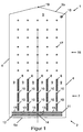
- FIG. 1 a plate-shaped bioreactor 1 is shown in a cross-sectional view, wherein the sectional plane extends along the plate extension.
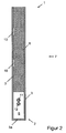
- FIG. 2 shows a cross section of a lower portion of the same bioreactor 1 along the line II-II in FIG FIG. 1 .
- the bioreactor 1 has a housing 2, which has two opposite side walls 3, two opposing side walls 4 and two opposite end walls 5a and 5b, which are each formed of a translucent material.
- the side walls 3 form the extended side surfaces of the plate-shaped housing 2, ie, the area of these side walls 3 is much larger than the area of the remaining walls 4, 5a and 5b, so that the housing has a flat shape.
- the bioreactor 1 is arranged so that the end wall 5a, the bottom of the bioreactor 1 and the end wall 5b, the top of the bioreactor. 1 forms, wherein the inclination angle of the housing 2 but can vary between nearly 0 ° and 90 °.
- the walls 3, 4, 5a and 5b define a reactor space 6 provided in the housing 2, which likewise has a flat configuration.
- the reactor chamber 6 five identical intermediate walls 8, which run parallel to one another and to the side walls 4, are arranged at a regular interval in a lower section 7, spaced from the end wall 5a.
- each intermediate wall 8 extends between the opposing extended or large side walls 3, so that the reactor space 6 is divided in the region of the intermediate walls 8 into six individual chambers or channels 9.
- the distance between adjacent partitions 8 and the distance between the outermost partitions 8 from the adjacent side wall 4 is at least 5 cm in each case.
- a plurality of openings or through-holes 10 are preferably formed along its length, via which adjacent channels 9 communicate with each other.
- the openings 9 are preferably formed in a region of the intermediate walls 8 which adjoins one of the extended side walls 3.
- two hoses or tubes 11 and 12 closed on both sides are fastened within the reactor space 6, each with two or one through a side wall 3 outwardly leading terminals 13 and connection 14 are provided, via the gas or in the tubes or tubes 11 and 12 can be introduced.
- the provision of two connections 13 has the advantage, in particular at low pressures, that uniform pressure conditions prevail in the entire hose or pipe.
- each second channel 9 In the tube or tube 11, a slot is formed below each second channel 9, can enter through the gas from the tube or tube 11 into the respective channel 9.
- the slots may have, for example, a length of 20 mm and a width of 0.5 mm.
- slots 15 it is also possible to provide in each case two boreholes arranged close to one another, each with a diameter of 2 mm, for example.
- the diameter of the tube or tube 11 should not be more than one third of the thickness of the reactor space 6 and could, for example, an outer diameter of 6 mm and an inner diameter of 1.5 mm have.
- the tube or the tube 12 is porous, so that when pumping gas through the port 14 gas in the form of fine gas bubbles from the tube or tube 12 exits.
- a number of columnar supports 17 are arranged, which connect the two opposite side walls 4 and against each other support. These supports 17 are used together with the intermediate walls 8 of the mechanical stabilization of the housing. 2
- connection 18 is further provided, introduced by the liquid in the reactor chamber 6 can be, and in the end wall 5 b, a port 19 is provided, can be discharged through the gas and liquid from the reactor chamber 6.
- the reactor space 6 is filled via port 18 with liquid culture medium and phototrophic organisms, to a level close to the end wall 5b.
- gas 6 preferably periodically and intermittently, pumped through the connections 13 in the tube or tube 11 in such a way that it exits in the form of large, continuous gas bubbles from the slots 15, which then in every second channel 9 in Direction of the end wall 5b through the culture medium (see also FIG. 3 ) and perpendicular to the extension direction of the intermediate walls 8 preferably have a diameter which corresponds to the width of the channels 9 or nearly corresponds.
- CO 2 is pumped through the port 14 in the tube or tube 11 and enters in the form of small, fine gas bubbles in the culture medium.
Landscapes
- Chemical & Material Sciences (AREA)
- Life Sciences & Earth Sciences (AREA)
- Health & Medical Sciences (AREA)
- Engineering & Computer Science (AREA)
- Organic Chemistry (AREA)
- Wood Science & Technology (AREA)
- Bioinformatics & Cheminformatics (AREA)
- Zoology (AREA)
- Genetics & Genomics (AREA)
- Biotechnology (AREA)
- Chemical Kinetics & Catalysis (AREA)
- Sustainable Development (AREA)
- Biomedical Technology (AREA)
- Biochemistry (AREA)
- General Engineering & Computer Science (AREA)
- General Health & Medical Sciences (AREA)
- Microbiology (AREA)
- Molecular Biology (AREA)
- Clinical Laboratory Science (AREA)
- Apparatus Associated With Microorganisms And Enzymes (AREA)
Claims (14)
- Bioréacteur pour la culture d'organismes phototrophiques dans un espace de réacteur avec :un bâti (3) en forme de parallélépipède et de plaque, perméable à la lumière, dans l'intérieur duquel l'espace de réacteur (6) est placé, le bâti (2) présentant deux parois latérales opposées plus grandes (3) qui forment les surfaces extérieures étendues du bâti en forme de plaque (2), deux parois latérales opposées plus petites (4) et deux parois frontales opposées (5a, 5b) qui délimitent l'espace de réacteur (6) et la distance entre les parois latérales plus petites (4) définissant la largeur de l'espace du réacteur (6), la distance entre les parois frontales (5a, 5b) définissant la longueur de l'espace du réacteur (6) et la distance entre les parois latérales plus grandes (3) définissant l'épaisseur de l'espace du réacteur (6),une multitude de parois intermédiaires (8) qui sont placées parallèlement aux parois latérales plus petites (4) et parallèlement les unes aux autres à proximité d'une première (5a) des deux parois frontales (5a, 5b) et en étant espacées de la première paroi frontale (5a) et en s'étendant sur toute l'épaisseur de l'espace de réacteur (6) et sur une partie de la longueur de l'espace de réacteur (6) si bien qu'une section conductrice de courant (7) de l'espace de réacteur (6) est formée avec une multitude de canaux conducteurs de courant (9), dont chacun se trouve entre deux parois intermédiaires voisines (8) ou entre l'une des parois latérales plus petites et une paroi intermédiaire voisine (8) et qu'une section de mélange libre (16) de l'espace de réacteur (6) est prévue entre les extrémités des parois intermédiaires qui sont détournées de la première paroi frontale (5a) et la seconde (5b) des deux parois frontales (5a, 5b)et avec un dispositif d'alimentation en gaz pour introduire du gaz dans chaque deuxième canal conducteur de courant (9) à proximité de la première paroi frontale (5a)caractérisé en ce que la section de mélange libre (16) s'étend sur au moins 50 % de la longueur de l'espace de réacteur (6) et que les canaux conducteurs de courant (9) présentent une largeur d'au moins 5 cm.
- Bioréacteur selon la revendication 1 pour lequel l'épaisseur de l'espace de réacteur (6) est d'1,5 à 5 cm.
- Bioréacteur selon la revendication 2 pour lequel l'épaisseur de l'espace de réacteur (6) est d'au moins 2,0 à 3 cm.
- Bioréacteur selon l'une des revendications précédentes pour lequel la largeur des canaux conducteurs de courant (9) est d'au moins 15 cm.
- Bioréacteur selon l'une des revendications précédentes pour lequel un certain nombre d'ouvertures espacées les unes des autres est prévu le long de la longueur des parois intermédiaires (8), ouvertures par lesquelles un échange de liquide peut avoir lieu entre des canaux conducteurs de courant (9) voisins.
- Bioréacteur selon l'une des revendications précédentes pour lequel le dispositif d'alimentation en gaz présente un ou plusieurs tuyaux (11) qui se trouvent dans l'espace de réacteur (6) entre la première paroi frontale (5a) et les extrémités tournées vers celle-ci des parois intermédiaires (8) et qui présentent des forures ou des fentes (10) par lesquelles du gaz est délivré dans les canaux conducteurs de courant respectifs (9).
- Bioréacteur selon la revendication 6 pour lequel le dispositif d'alimentation en gaz est adapté pour amener du gaz sous forme de bulles de gaz individuelles (20) dans lescanaux conducteurs de courant respectifs (9), lorsque l'espace de réacteur (6) est rempli d'un milieu de culture liquide et d'organismes phototrophiques, les bulles de gaz (20) présentant un grand diamètre d'au moins 3 cm.
- Bioréacteur selon la revendication 6 ou 7 pour lequel le dispositif d'alimentation en gaz est adapté pour amener le gaz dans les canaux conducteurs de courant correspondants (9) de manière saccadée telle qu'une nouvelle bulle de gaz (20) n'est produite que lorsque la bulle de gaz précédente (20) a entièrement traversé le milieu de culture dans l'espace de réacteur (6).
- Bioréacteur selon l'une des revendications précédentes pour lequel la longueur de l'espace de réacteur (6) est plus grande que sa largeur.
- Bioréacteur selon l'une des revendications précédentes pour lequel une multitude de colonnes (17) espacées les unes des autres est placée dans la section de mélange (16), colonnes qui relient respectivement les deux grandes parois latérales (3) du bâti (2) l'une à l'autre et qui sont configurées chacune de telle manière qu'elles s'effilent en direction d'au moins l'une de leurs deux extrémités.
- Procédé pour la culture d'organismes phototrophiques dans un bioréacteur selon l'une des revendications précédentes qui présente les étapes suivantes :introduction d'un milieu de culture liquide dans l'espace de réacteur (6) d'un bioréacteur (1) selon l'une des revendications précédentes,introduction d'organismes phototrophiques dans l'espace de réacteur (6),irradiation d'une grande paroi latérale (3) du bâti (2) du bioréacteur (1) avec de la lumière etintroduction de gaz dans chaque deuxième canal conducteur de courant (9) à l'aide du dispositif d'alimentation en gaz, le gaz étant amené sous forme de bulles individuelles (20) dont le grand diamètre est d'au moins 3 cm.
- Procédé selon la revendication 11 pour lequel le gaz est introduit à l'aide du dispositif d'alimentation en gaz de telle manière que la vitesse des bulles de gaz (20) qui traversent le milieu de culture dans les canaux conducteurs de courant (9) est d'au moins 0,5 m/s.
- Procédé selon la revendication 11 ou 12 pour lequel le gaz est introduit à travers une paroi frontale (5a) avec un rapport de flux volumique à la surface de la paroi frontale, par laquelle le gaz est introduit, d'au moins 0,02 m/s.
- Procédé selon l'une des revendications 11 à 13 pour lequel le gaz est introduit dans les canaux conducteurs de courant correspondants (9) de manière saccadée telle qu'une nouvelle bulle de gaz (20) n'est produite que lorsque la bulle de gaz précédente (20) a entièrement traversé le milieu de culture dans l'espace de réacteur (6).
Priority Applications (3)
| Application Number | Priority Date | Filing Date | Title |
|---|---|---|---|
| ES09154581T ES2378191T3 (es) | 2009-03-08 | 2009-03-08 | Biorreactor y procedimiento para hacer funcionar un biorreactor |
| EP09154581A EP2228432B1 (fr) | 2009-03-08 | 2009-03-08 | Bioréacteur et procédé destiné au fonctionnement d'un bioréacteur |
| AT09154581T ATE534725T1 (de) | 2009-03-08 | 2009-03-08 | Bioreaktor und verfahren zum betrieb eines bioreaktors |
Applications Claiming Priority (1)
| Application Number | Priority Date | Filing Date | Title |
|---|---|---|---|
| EP09154581A EP2228432B1 (fr) | 2009-03-08 | 2009-03-08 | Bioréacteur et procédé destiné au fonctionnement d'un bioréacteur |
Publications (2)
| Publication Number | Publication Date |
|---|---|
| EP2228432A1 EP2228432A1 (fr) | 2010-09-15 |
| EP2228432B1 true EP2228432B1 (fr) | 2011-11-23 |
Family
ID=40847588
Family Applications (1)
| Application Number | Title | Priority Date | Filing Date |
|---|---|---|---|
| EP09154581A Not-in-force EP2228432B1 (fr) | 2009-03-08 | 2009-03-08 | Bioréacteur et procédé destiné au fonctionnement d'un bioréacteur |
Country Status (3)
| Country | Link |
|---|---|
| EP (1) | EP2228432B1 (fr) |
| AT (1) | ATE534725T1 (fr) |
| ES (1) | ES2378191T3 (fr) |
Families Citing this family (5)
| Publication number | Priority date | Publication date | Assignee | Title |
|---|---|---|---|---|
| DE102011116237A1 (de) * | 2011-10-18 | 2013-04-18 | Thomas Warscheid | Verfahren und Vorrichtung zur Kultivierung von phototrophen Organismen |
| AT516115A1 (de) * | 2014-07-24 | 2016-02-15 | Ecoduna Ag | Verfahren für einen photochemischen, wie photokatalytischen und/oder photosynthetischen, Prozess |
| DE102017001041B4 (de) | 2017-01-27 | 2024-01-25 | Jörn Jander | Photobioreaktor und Verfahren zur Kultivierung von phototrophen Mikroalgen |
| KR101938871B1 (ko) * | 2017-09-29 | 2019-01-16 | 고려대학교 산학협력단 | 광합성 생물의 스케일업 배양이 용이한 투명 광생물 반응기 및 그 제작 방법 |
| DE102020113163B4 (de) | 2020-05-14 | 2024-04-25 | BAF Brandenburger Algenfarm GmbH | Fotobioreaktor zur Kultivierung von Mikroorganismen, insbesondere von Algen |
Family Cites Families (4)
| Publication number | Priority date | Publication date | Assignee | Title |
|---|---|---|---|---|
| BE790132R (fr) * | 1971-10-14 | 1973-04-16 | Basf Ag | Procede et dispositif d'aeration de |
| JPS5455780A (en) * | 1977-10-05 | 1979-05-04 | Kanegafuchi Chem Ind Co Ltd | Fermentor for aerobic microorganisms |
| WO1991007080A1 (fr) * | 1989-11-22 | 1991-05-30 | Martek Corporation | Photobioreacteur |
| DE19916597A1 (de) | 1999-04-13 | 2000-10-19 | Fraunhofer Ges Forschung | Photobioreaktor mit verbessertem Lichteintrag durch Oberflächenvergrößerung, Wellenlängenschieber oder Lichttransport |
-
2009
- 2009-03-08 AT AT09154581T patent/ATE534725T1/de active
- 2009-03-08 ES ES09154581T patent/ES2378191T3/es active Active
- 2009-03-08 EP EP09154581A patent/EP2228432B1/fr not_active Not-in-force
Also Published As
| Publication number | Publication date |
|---|---|
| ES2378191T3 (es) | 2012-04-09 |
| EP2228432A1 (fr) | 2010-09-15 |
| ATE534725T1 (de) | 2011-12-15 |
Similar Documents
| Publication | Publication Date | Title |
|---|---|---|
| WO2002031102A1 (fr) | Bioreacteur pour la culture de micro-organismes et son procede de fabrication | |
| DE19814253C2 (de) | Verfahren zur Herstellung von Biomasse mittels Photosynthese | |
| EP2326706B1 (fr) | Installation pour la culture et la reproduction de micro-organismes (par exemple, des algues) sous lumière intensive | |
| DE60110765T2 (de) | Verfahren und behälter für hydroponische und aeroponische kultur | |
| EP2446016B1 (fr) | Procédé de production de biomasse et photobioréacteur pour cultiver des organismes ou des cellules phototrophes ou mixotrophes | |
| EP2228432B1 (fr) | Bioréacteur et procédé destiné au fonctionnement d'un bioréacteur | |
| EP2520642A1 (fr) | Photobioréacteur avec une source lumineuse à mouvement rotatif oscillant | |
| DE3601705A1 (de) | Gasblasenerzeuger und vorrichtung und verfahren zum zuechten von zellen | |
| DE3248543C2 (fr) | ||
| EP1995304A1 (fr) | Procédés et dispositifs destinés à la fabrication commerciale d'huiles biologiques | |
| DE4411486C1 (de) | Verfahren und Einrichtung zur Kultivation und Fermentation von Mikroorganismen oder Zellen in flüssigen Medien | |
| WO2015106733A9 (fr) | Photobioréacteur et procédé de culture sur couches minces | |
| EP2533627B1 (fr) | Bâtiment | |
| EP0085688B1 (fr) | Procede et installation pour executer des operations photochimiques | |
| EP2316917A1 (fr) | Procédé de culture de mixotrophes de microorganismes et/ou de cellules | |
| EP0968273B1 (fr) | Installation pour effectuer des reactions photochimiques et photocatalytiques et des processus photoinductifs | |
| EP2427541A2 (fr) | Dispositif pour l'exécution de processus photochimiques | |
| DE3390269C2 (de) | Fermenter | |
| DE102008031769B4 (de) | Bioreaktor in Flachbauweise | |
| DE102017101725A1 (de) | Fotobioreaktor zur Kultivierung von aquatischen Mikroorganismen | |
| DE102010043587B4 (de) | Zuchtvorrichtung für phototrophe Kulturen, sowie Verfahren zu deren Steuerung | |
| DE102009022754A1 (de) | Photobioreaktor | |
| DE102016206918A1 (de) | Bioreaktor für die Kultivierung von Organismen mit einer verbesserten Gaszuführung | |
| EP3372665A1 (fr) | Dispositif, système et procédé de production d'organismes phototrophes | |
| DE102014221428B4 (de) | Neues Flachplatten-Airlift-Reaktorsystem |
Legal Events
| Date | Code | Title | Description |
|---|---|---|---|
| PUAI | Public reference made under article 153(3) epc to a published international application that has entered the european phase |
Free format text: ORIGINAL CODE: 0009012 |
|
| AK | Designated contracting states |
Kind code of ref document: A1 Designated state(s): AT BE BG CH CY CZ DE DK EE ES FI FR GB GR HR HU IE IS IT LI LT LU LV MC MK MT NL NO PL PT RO SE SI SK TR |
|
| AX | Request for extension of the european patent |
Extension state: AL BA RS |
|
| GRAP | Despatch of communication of intention to grant a patent |
Free format text: ORIGINAL CODE: EPIDOSNIGR1 |
|
| 17P | Request for examination filed |
Effective date: 20110304 |
|
| AKX | Designation fees paid |
Designated state(s): AT BE BG CH CY CZ DE DK EE ES FI FR GB GR HR HU IE IS IT LI LT LU LV MC MK MT NL NO PL PT RO SE SI SK TR |
|
| GRAS | Grant fee paid |
Free format text: ORIGINAL CODE: EPIDOSNIGR3 |
|
| GRAA | (expected) grant |
Free format text: ORIGINAL CODE: 0009210 |
|
| RAP1 | Party data changed (applicant data changed or rights of an application transferred) |
Owner name: SSC STRATEGIC SCIENCE CONSULT GMBH |
|
| AK | Designated contracting states |
Kind code of ref document: B1 Designated state(s): AT BE BG CH CY CZ DE DK EE ES FI FR GB GR HR HU IE IS IT LI LT LU LV MC MK MT NL NO PL PT RO SE SI SK TR |
|
| REG | Reference to a national code |
Ref country code: GB Ref legal event code: FG4D Free format text: NOT ENGLISH |
|
| REG | Reference to a national code |
Ref country code: CH Ref legal event code: EP |
|
| REG | Reference to a national code |
Ref country code: IE Ref legal event code: FG4D Free format text: LANGUAGE OF EP DOCUMENT: GERMAN |
|
| REG | Reference to a national code |
Ref country code: DE Ref legal event code: R096 Ref document number: 502009001989 Country of ref document: DE Effective date: 20120202 |
|
| REG | Reference to a national code |
Ref country code: CH Ref legal event code: NV Representative=s name: E. BLUM & CO. AG PATENT- UND MARKENANWAELTE VSP |
|
| REG | Reference to a national code |
Ref country code: NL Ref legal event code: VDEP Effective date: 20111123 |
|
| REG | Reference to a national code |
Ref country code: ES Ref legal event code: FG2A Ref document number: 2378191 Country of ref document: ES Kind code of ref document: T3 Effective date: 20120409 |
|
| LTIE | Lt: invalidation of european patent or patent extension |
Effective date: 20111123 |
|
| PG25 | Lapsed in a contracting state [announced via postgrant information from national office to epo] |
Ref country code: IS Free format text: LAPSE BECAUSE OF FAILURE TO SUBMIT A TRANSLATION OF THE DESCRIPTION OR TO PAY THE FEE WITHIN THE PRESCRIBED TIME-LIMIT Effective date: 20120323 Ref country code: NO Free format text: LAPSE BECAUSE OF FAILURE TO SUBMIT A TRANSLATION OF THE DESCRIPTION OR TO PAY THE FEE WITHIN THE PRESCRIBED TIME-LIMIT Effective date: 20120223 Ref country code: LT Free format text: LAPSE BECAUSE OF FAILURE TO SUBMIT A TRANSLATION OF THE DESCRIPTION OR TO PAY THE FEE WITHIN THE PRESCRIBED TIME-LIMIT Effective date: 20111123 |
|
| PG25 | Lapsed in a contracting state [announced via postgrant information from national office to epo] |
Ref country code: SI Free format text: LAPSE BECAUSE OF FAILURE TO SUBMIT A TRANSLATION OF THE DESCRIPTION OR TO PAY THE FEE WITHIN THE PRESCRIBED TIME-LIMIT Effective date: 20111123 Ref country code: HR Free format text: LAPSE BECAUSE OF FAILURE TO SUBMIT A TRANSLATION OF THE DESCRIPTION OR TO PAY THE FEE WITHIN THE PRESCRIBED TIME-LIMIT Effective date: 20111123 Ref country code: SE Free format text: LAPSE BECAUSE OF FAILURE TO SUBMIT A TRANSLATION OF THE DESCRIPTION OR TO PAY THE FEE WITHIN THE PRESCRIBED TIME-LIMIT Effective date: 20111123 Ref country code: NL Free format text: LAPSE BECAUSE OF FAILURE TO SUBMIT A TRANSLATION OF THE DESCRIPTION OR TO PAY THE FEE WITHIN THE PRESCRIBED TIME-LIMIT Effective date: 20111123 Ref country code: LV Free format text: LAPSE BECAUSE OF FAILURE TO SUBMIT A TRANSLATION OF THE DESCRIPTION OR TO PAY THE FEE WITHIN THE PRESCRIBED TIME-LIMIT Effective date: 20111123 Ref country code: PT Free format text: LAPSE BECAUSE OF FAILURE TO SUBMIT A TRANSLATION OF THE DESCRIPTION OR TO PAY THE FEE WITHIN THE PRESCRIBED TIME-LIMIT Effective date: 20120323 Ref country code: GR Free format text: LAPSE BECAUSE OF FAILURE TO SUBMIT A TRANSLATION OF THE DESCRIPTION OR TO PAY THE FEE WITHIN THE PRESCRIBED TIME-LIMIT Effective date: 20120224 |
|
| REG | Reference to a national code |
Ref country code: IE Ref legal event code: FD4D |
|
| PG25 | Lapsed in a contracting state [announced via postgrant information from national office to epo] |
Ref country code: CY Free format text: LAPSE BECAUSE OF FAILURE TO SUBMIT A TRANSLATION OF THE DESCRIPTION OR TO PAY THE FEE WITHIN THE PRESCRIBED TIME-LIMIT Effective date: 20111123 |
|
| PGFP | Annual fee paid to national office [announced via postgrant information from national office to epo] |
Ref country code: IT Payment date: 20120331 Year of fee payment: 4 |
|
| PG25 | Lapsed in a contracting state [announced via postgrant information from national office to epo] |
Ref country code: CZ Free format text: LAPSE BECAUSE OF FAILURE TO SUBMIT A TRANSLATION OF THE DESCRIPTION OR TO PAY THE FEE WITHIN THE PRESCRIBED TIME-LIMIT Effective date: 20111123 Ref country code: EE Free format text: LAPSE BECAUSE OF FAILURE TO SUBMIT A TRANSLATION OF THE DESCRIPTION OR TO PAY THE FEE WITHIN THE PRESCRIBED TIME-LIMIT Effective date: 20111123 Ref country code: SK Free format text: LAPSE BECAUSE OF FAILURE TO SUBMIT A TRANSLATION OF THE DESCRIPTION OR TO PAY THE FEE WITHIN THE PRESCRIBED TIME-LIMIT Effective date: 20111123 Ref country code: IE Free format text: LAPSE BECAUSE OF FAILURE TO SUBMIT A TRANSLATION OF THE DESCRIPTION OR TO PAY THE FEE WITHIN THE PRESCRIBED TIME-LIMIT Effective date: 20111123 Ref country code: BG Free format text: LAPSE BECAUSE OF FAILURE TO SUBMIT A TRANSLATION OF THE DESCRIPTION OR TO PAY THE FEE WITHIN THE PRESCRIBED TIME-LIMIT Effective date: 20120223 Ref country code: DK Free format text: LAPSE BECAUSE OF FAILURE TO SUBMIT A TRANSLATION OF THE DESCRIPTION OR TO PAY THE FEE WITHIN THE PRESCRIBED TIME-LIMIT Effective date: 20111123 |
|
| PG25 | Lapsed in a contracting state [announced via postgrant information from national office to epo] |
Ref country code: RO Free format text: LAPSE BECAUSE OF FAILURE TO SUBMIT A TRANSLATION OF THE DESCRIPTION OR TO PAY THE FEE WITHIN THE PRESCRIBED TIME-LIMIT Effective date: 20111123 Ref country code: PL Free format text: LAPSE BECAUSE OF FAILURE TO SUBMIT A TRANSLATION OF THE DESCRIPTION OR TO PAY THE FEE WITHIN THE PRESCRIBED TIME-LIMIT Effective date: 20111123 |
|
| PLBE | No opposition filed within time limit |
Free format text: ORIGINAL CODE: 0009261 |
|
| STAA | Information on the status of an ep patent application or granted ep patent |
Free format text: STATUS: NO OPPOSITION FILED WITHIN TIME LIMIT |
|
| BERE | Be: lapsed |
Owner name: SSC STRATEGIC SCIENCE CONSULT G.M.B.H. Effective date: 20120331 |
|
| 26N | No opposition filed |
Effective date: 20120824 |
|
| PG25 | Lapsed in a contracting state [announced via postgrant information from national office to epo] |
Ref country code: MC Free format text: LAPSE BECAUSE OF NON-PAYMENT OF DUE FEES Effective date: 20120331 |
|
| REG | Reference to a national code |
Ref country code: DE Ref legal event code: R097 Ref document number: 502009001989 Country of ref document: DE Effective date: 20120824 |
|
| PG25 | Lapsed in a contracting state [announced via postgrant information from national office to epo] |
Ref country code: BE Free format text: LAPSE BECAUSE OF NON-PAYMENT OF DUE FEES Effective date: 20120331 |
|
| PG25 | Lapsed in a contracting state [announced via postgrant information from national office to epo] |
Ref country code: MK Free format text: LAPSE BECAUSE OF FAILURE TO SUBMIT A TRANSLATION OF THE DESCRIPTION OR TO PAY THE FEE WITHIN THE PRESCRIBED TIME-LIMIT Effective date: 20111123 |
|
| PG25 | Lapsed in a contracting state [announced via postgrant information from national office to epo] |
Ref country code: FI Free format text: LAPSE BECAUSE OF FAILURE TO SUBMIT A TRANSLATION OF THE DESCRIPTION OR TO PAY THE FEE WITHIN THE PRESCRIBED TIME-LIMIT Effective date: 20111123 |
|
| PG25 | Lapsed in a contracting state [announced via postgrant information from national office to epo] |
Ref country code: MT Free format text: LAPSE BECAUSE OF FAILURE TO SUBMIT A TRANSLATION OF THE DESCRIPTION OR TO PAY THE FEE WITHIN THE PRESCRIBED TIME-LIMIT Effective date: 20111123 |
|
| PG25 | Lapsed in a contracting state [announced via postgrant information from national office to epo] |
Ref country code: IT Free format text: LAPSE BECAUSE OF NON-PAYMENT OF DUE FEES Effective date: 20130308 |
|
| PG25 | Lapsed in a contracting state [announced via postgrant information from national office to epo] |
Ref country code: TR Free format text: LAPSE BECAUSE OF FAILURE TO SUBMIT A TRANSLATION OF THE DESCRIPTION OR TO PAY THE FEE WITHIN THE PRESCRIBED TIME-LIMIT Effective date: 20111123 |
|
| PG25 | Lapsed in a contracting state [announced via postgrant information from national office to epo] |
Ref country code: LU Free format text: LAPSE BECAUSE OF NON-PAYMENT OF DUE FEES Effective date: 20120308 |
|
| PG25 | Lapsed in a contracting state [announced via postgrant information from national office to epo] |
Ref country code: HU Free format text: LAPSE BECAUSE OF FAILURE TO SUBMIT A TRANSLATION OF THE DESCRIPTION OR TO PAY THE FEE WITHIN THE PRESCRIBED TIME-LIMIT Effective date: 20090308 |
|
| REG | Reference to a national code |
Ref country code: FR Ref legal event code: PLFP Year of fee payment: 8 |
|
| REG | Reference to a national code |
Ref country code: FR Ref legal event code: PLFP Year of fee payment: 9 |
|
| REG | Reference to a national code |
Ref country code: FR Ref legal event code: PLFP Year of fee payment: 10 |
|
| PGFP | Annual fee paid to national office [announced via postgrant information from national office to epo] |
Ref country code: GB Payment date: 20190306 Year of fee payment: 11 Ref country code: CH Payment date: 20190314 Year of fee payment: 11 |
|
| PGFP | Annual fee paid to national office [announced via postgrant information from national office to epo] |
Ref country code: AT Payment date: 20190226 Year of fee payment: 11 |
|
| PGFP | Annual fee paid to national office [announced via postgrant information from national office to epo] |
Ref country code: ES Payment date: 20190401 Year of fee payment: 11 |
|
| REG | Reference to a national code |
Ref country code: CH Ref legal event code: PL |
|
| REG | Reference to a national code |
Ref country code: AT Ref legal event code: MM01 Ref document number: 534725 Country of ref document: AT Kind code of ref document: T Effective date: 20200308 |
|
| PG25 | Lapsed in a contracting state [announced via postgrant information from national office to epo] |
Ref country code: LI Free format text: LAPSE BECAUSE OF NON-PAYMENT OF DUE FEES Effective date: 20200331 Ref country code: CH Free format text: LAPSE BECAUSE OF NON-PAYMENT OF DUE FEES Effective date: 20200331 Ref country code: AT Free format text: LAPSE BECAUSE OF NON-PAYMENT OF DUE FEES Effective date: 20200308 Ref country code: FR Free format text: LAPSE BECAUSE OF NON-PAYMENT OF DUE FEES Effective date: 20200331 |
|
| PGFP | Annual fee paid to national office [announced via postgrant information from national office to epo] |
Ref country code: FR Payment date: 20201123 Year of fee payment: 13 |
|
| PGRI | Patent reinstated in contracting state [announced from national office to epo] |
Ref country code: FR Effective date: 20201229 |
|
| GBPC | Gb: european patent ceased through non-payment of renewal fee |
Effective date: 20200308 |
|
| PG25 | Lapsed in a contracting state [announced via postgrant information from national office to epo] |
Ref country code: GB Free format text: LAPSE BECAUSE OF NON-PAYMENT OF DUE FEES Effective date: 20200308 |
|
| REG | Reference to a national code |
Ref country code: ES Ref legal event code: FD2A Effective date: 20210728 |
|
| PG25 | Lapsed in a contracting state [announced via postgrant information from national office to epo] |
Ref country code: ES Free format text: LAPSE BECAUSE OF NON-PAYMENT OF DUE FEES Effective date: 20200309 |
|
| REG | Reference to a national code |
Ref country code: DE Ref legal event code: R081 Ref document number: 502009001989 Country of ref document: DE Owner name: CELLPARC GMBH, DE Free format text: FORMER OWNER: SSC STRATEGIC SCIENCE CONSULT GMBH, 22761 HAMBURG, DE |
|
| PG25 | Lapsed in a contracting state [announced via postgrant information from national office to epo] |
Ref country code: FR Free format text: LAPSE BECAUSE OF NON-PAYMENT OF DUE FEES Effective date: 20220331 |
|
| PGFP | Annual fee paid to national office [announced via postgrant information from national office to epo] |
Ref country code: DE Payment date: 20230331 Year of fee payment: 15 |
|
| REG | Reference to a national code |
Ref country code: DE Ref legal event code: R119 Ref document number: 502009001989 Country of ref document: DE |
|
| PG25 | Lapsed in a contracting state [announced via postgrant information from national office to epo] |
Ref country code: DE Free format text: LAPSE BECAUSE OF NON-PAYMENT OF DUE FEES Effective date: 20241001 |
|
| PG25 | Lapsed in a contracting state [announced via postgrant information from national office to epo] |
Ref country code: DE Free format text: LAPSE BECAUSE OF NON-PAYMENT OF DUE FEES Effective date: 20241001 |