EP2228540B1 - Agencement doté d'une pompe à vide - Google Patents
Agencement doté d'une pompe à vide Download PDFInfo
- Publication number
- EP2228540B1 EP2228540B1 EP10002262.3A EP10002262A EP2228540B1 EP 2228540 B1 EP2228540 B1 EP 2228540B1 EP 10002262 A EP10002262 A EP 10002262A EP 2228540 B1 EP2228540 B1 EP 2228540B1
- Authority
- EP
- European Patent Office
- Prior art keywords
- flange
- pump
- chamber
- force
- vacuum pump
- Prior art date
- Legal status (The legal status is an assumption and is not a legal conclusion. Google has not performed a legal analysis and makes no representation as to the accuracy of the status listed.)
- Active
Links
Images


Classifications
-
- F—MECHANICAL ENGINEERING; LIGHTING; HEATING; WEAPONS; BLASTING
- F04—POSITIVE - DISPLACEMENT MACHINES FOR LIQUIDS; PUMPS FOR LIQUIDS OR ELASTIC FLUIDS
- F04D—NON-POSITIVE-DISPLACEMENT PUMPS
- F04D19/00—Axial-flow pumps
- F04D19/02—Multi-stage pumps
- F04D19/04—Multi-stage pumps specially adapted to the production of a high vacuum, e.g. molecular pumps
- F04D19/042—Turbomolecular vacuum pumps
-
- F—MECHANICAL ENGINEERING; LIGHTING; HEATING; WEAPONS; BLASTING
- F04—POSITIVE - DISPLACEMENT MACHINES FOR LIQUIDS; PUMPS FOR LIQUIDS OR ELASTIC FLUIDS
- F04D—NON-POSITIVE-DISPLACEMENT PUMPS
- F04D19/00—Axial-flow pumps
- F04D19/02—Multi-stage pumps
- F04D19/04—Multi-stage pumps specially adapted to the production of a high vacuum, e.g. molecular pumps
- F04D19/046—Combinations of two or more different types of pumps
-
- F—MECHANICAL ENGINEERING; LIGHTING; HEATING; WEAPONS; BLASTING
- F04—POSITIVE - DISPLACEMENT MACHINES FOR LIQUIDS; PUMPS FOR LIQUIDS OR ELASTIC FLUIDS
- F04D—NON-POSITIVE-DISPLACEMENT PUMPS
- F04D29/00—Details, component parts, or accessories
- F04D29/60—Mounting; Assembling; Disassembling
- F04D29/601—Mounting; Assembling; Disassembling specially adapted for elastic fluid pumps
Definitions
- the invention relates to an arrangement with a vacuum pump in each case according to the preamble of the independent claims 1 and 3.
- Vacuum pump and recipient assemblies hereafter referred to as chambers, are subject to a variety of geometrical design requirements.
- chambers are subject to a variety of geometrical design requirements.
- mass spectrometers there is a desire for more compact dimensions of the overall system. This often leads to a positioning of the vacuum pump in the terminal, in which their accessibility is considerably limited. Nevertheless, the service to these vacuum pumps, such as the preventive replacement of rolling bearings, should be easily possible.
- the WO 99/61799 A1 discloses a vacuum pump of an arrangement according to the preamble of claim 1.
- the US 2008/0309071 A1 discloses an assembly having a vacuum pump having a pump flange, a chamber having a chamber flange, and a flange connection comprising a pump flange and chamber flange for vacuum-sealing chamber and vacuum pump.
- the flange connection comprises a power transmission structure which transmits a force from an introduction point to an operative point located in the flange connection.
- the power transmission structure converts a planar introduction force into an axial contact force.
- the assembly includes a power transmission structure which transmits a force from a point of introduction to at least one point of action located elsewhere in the flange connection.
- a power transmission structure which transmits a force from a point of introduction to at least one point of action located elsewhere in the flange connection.
- a power transmission structure is inexpensive to produce and avoids expensive designs of the vacuum pump, in particular its vacuum-tight housing.
- the pump flange comprises at least two suction openings.
- the arrangement is cost-effective, because the power transmission structure is adapted to implement a planar initiating force in an axial contact force.
- Planar here means that the direction of force lies in a plane parallel to the flange plane.
- Axial means standing vertically on the flange plane.
- Claim 3 proposes to provide a lever mechanism which transmits the force introduced at one location of the flange connection to another location of the flange connection.
- a damping element in the power transmission structure provides for reduced vibration transmission across the flange connection. This allows the use of the assembly in applications that are sensitive to shocks.
- FIG Fig. 1 An exemplary overall system with an arrangement of vacuum pump and chamber is shown in FIG Fig. 1 shown.
- the chamber 2 is designed as a multi-chamber system for differential pumping and therefore has a fore-vacuum chamber 21, a central chamber 22 and a high-vacuum chamber 23. These chambers are interconnected via openings 25 and 26 through which, for example, a gas particle jet passes.
- a detector for example a mass spectrometer 24, is provided, which is controlled by a drive assembly 36.
- the chamber has a chamber flange 20 with which a pump flange 10 is connected.
- the pump flange is part of the vacuum pump 1, which comprises a shaft 11 which is rotatably supported by a fore vacuum side bearing 12, for example a roller bearing, and a high vacuum side bearing 13, for example a permanent magnet bearing.
- the shaft is rotated by a drive 14 in rotation, so that in the pumping stages 15 and 16, compression and suction capacity are built up.
- the inlet of the pumping stage 15 is connected via an intake port 27 to the central chamber in connection.
- the pumping stage 16 is in turn connected via a suction port 28 with the high vacuum chamber 23 in connection. Gas enters through the suction port 28 in the vacuum pump, is compressed by the pumping stage 16, then merged with the entering through the suction port 27 into the vacuum pump gas and further compressed together with this of the pumping stage 15.
- Outlet of the vacuum pump and Vorvakuumhunt 21 are connected via a Vorvakuumzutechnisch 41 with a backing pump 40, which further compresses the gas and expels against the atmosphere.
- the pumping stages 15 and 16 are preferably designed as turbomolecular pumping stages.
- the vacuum pump and chamber connected together by the vacuum-tight and chamber flange and pump flange are supported by a frame 30.
- This frame also carries the drive assembly 36 of the mass spectrometer and further components 33, 34 and 35, such as power supplies, computing units and the like.
- the frame is covered with a panel 31.
- Vacuum pump and chamber are accessible by a flap 32, but surrounded by the other supported by the frame assemblies and components. The flange is therefore difficult and essentially accessible only from the side facing the flap 32. Assembly and disassembly of the vacuum pump can therefore only be done from this side.
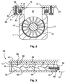
- FIG. 2 It shows Fig. 2 the power transmission structure 65 in cross section to the shaft 11 by vacuum pump and flange connection along the line I-I '.
- Chamber flange 20 and pump flange 10 touch each other.
- a Seal 19 is provided, which surrounds the suction port 27 on the flange.
- a fixing screw 51 attaches a bracket 50 on the chamber flange. Between the bracket and the pump flange, a first expansion element 52 and a second expansion element 53 are arranged.
- Fig. 3 is the corresponding section along the line II-II 'and shown parallel to the shaft. It will be appreciated that a portion of the bracket 50, first expansion member 52, second expansion member 53, and a portion of the pump flange 10 lie in a common plane.
- the first expansion element has a wedge surface 58 and the second expansion element has a wedge surface 58 '. These wedge surfaces touch each other so that a shift against each other is possible.
- the displacement is effected by a force introduction screw 55, which projects through a through hole in an arm 54 of the first expansion element, and engages the threaded part in a thread of the second expansion element. By tightening the screw, a planar force is exerted, which shifts the two expansion elements against each other.
- the spreading elements 52 and 53 cause a force in the force transmission structure 65 to be transferred from the point of introduction 56 to a point of action 59.
- This power transmission makes it possible to generate a contact pressure 60 also in the places which are related by FIG. 1 described and surrounding the vacuum pump components are not accessible.
- Another advantage of this example is that in addition to the power transmission and a force distribution over the pump flange takes place and so a uniform contact pressure is achieved. With the number of wedge surfaces and their angle, the force distribution of the force introduced on the flange 10 can be adjusted.
- the bracket can be made in one piece with the chamber flange. A separation is advantageous if an existing system is to be retrofitted. In addition, omitted in the design according to this example changes the pump flange, so that a standard pump can be used.
- the number of pumping stages of the vacuum pump and the number of gas inlets is only an example and not a limitation.
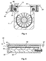
- FIGS. 4 and 5 A development of this embodiment show the FIGS. 4 and 5 , The pump flange 10 'of the vacuum pump 1' is not completely pulled in this development against the chamber flange 20 '. Between pump flange and chamber flange remains a gap which is created by the seal 19 '. The force introduced and transmitted via the force transmission structure 65 'is therefore such that the seal 19' is not squeezed to the touch of the flanges. However, the contact pressure and thus pinch seal is sufficient to ensure a vacuum-tight connection.
- the power transmission structure has here also spreading 52 'and 53', which are provided between the pump flange and the bracket 50 '.
- a damping element 66 ' is arranged between the first expansion element 52' and the flange.
- FIG. 5 A section along the line III-III 'by this development is in Fig. 5 shown. Between chamber flange 20 'and pump flange 10', the gap 67 'is provided.
- the damping element 66' is arranged between the pump flange and the first expansion element 52 '.
- the spreading 52 'and 53' act with pump flange, chamber flange and bracket as in the FIGS. 2 and 3 described together.
- the damping element causes together with the seal an advantageous vibration isolation. Vibrations, which are generated for example by the rapid rotation of the shaft in the vacuum pump, are transmitted by damping element and seal only to a greatly reduced extent, so that this arrangement brings an advantage in vibration critical applications.
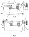
- FIGS. 6 and 7 Another example of power transmission structure show the FIGS. 6 and 7 , In Fig. 6 First, a longitudinal section along the shaft 111 of the vacuum pump 100 is shown.
- the vacuum pump has two pumping stages 115 and 116. The leading to the pumping stages gas inlets are surrounded by seals 119.
- the pump flange 110 has a flange extension 152. This is engaged with a counter-angle 150, wherein in Fig. 6 the dismantled state is shown. The counter-angle is fastened with a fastening screw 151 on the chamber flange 120.
- Fig. 7 is the arrangement after Fig. 6 shown in the assembled state.
- the pump flange is screwed to the chamber flange 120 and introduced an axial force 162 at the point of introduction 156
- the flange extension and the counter angle act as a lever mechanism and generate at the point of action 159 an axial contact pressure 160.
- the lever mechanism causes in the power transmission structure 165 a Force is transmitted from the point of introduction 156 to an active site 159. This power transmission makes it possible to generate a contact pressure 160 also in the places associated with FIG. 1 described and surrounding the vacuum pump components are not accessible.
- the counter-angle can be made in one piece with the chamber flange. A separation is advantageous if an existing system is to be retrofitted.
- the number of pumping stages of the vacuum pump and the number of gas inlets is only an example and not a restriction.
- a damping element can be arranged, which cooperates with the seal as in the development of the first example and thus creates a vibration-decoupled flange connection.
- FIG. 8 The principle of action of the first example FIGS. 2 and 3 , whose training after 4 and 5 and the second example 6 and 7 is in FIG. 8 shown.
- the flange has suction openings 71 and 72, via which pump stages for a medium and higher vacuum are accessible.
- the flange has a circumference formed by the edges 75, 76, 77 and 78. In the in FIG. 1 shown installation position of the vacuum pump, only the edge 76 is accessible for mounting and dismounting the vacuum pump. For this flange to enter into a vacuum-tight flange connection with the flange of the chamber, a substantially perpendicular contact force must act on all edges along the edges.
- the power transmission structure makes it possible to initiate a force in a first section 80 of the circumference and to bring it into effect in another section 81, which is different from the first section, and in particular to generate an axial contact pressure 87 there.
- the first section can be a planar force 86, as explained in the first example, or an axial force 85, as explained in the second example.
- the measures can be used together with known fasteners such as clamp screws and claws.
Landscapes
- Engineering & Computer Science (AREA)
- Mechanical Engineering (AREA)
- General Engineering & Computer Science (AREA)
- Compressors, Vaccum Pumps And Other Relevant Systems (AREA)
- Applications Or Details Of Rotary Compressors (AREA)
Claims (5)
- Agencement comprenant une pompe à vide (1), laquelle comporte une bride de pompe (10 ; 70), une chambre (2), laquelle comporte une bride de chambre (20), et une liaison à bride (3) englobant la bride de pompe et la bride de chambre pour effectuer une liaison étanche au vide de la chambre et de la pompe à vide, dans lequel l'agencement inclut une structure de transmission de force, laquelle transmet une force depuis un emplacement d'application (56) à au moins un emplacement d'action (59) situé dans la liaison à bride, dans lequel la bride de pompe (10 ; 70) inclut au moins deux ouvertures d'aspiration (27 ; 28) qui sont reliées respectivement à un étage de pompe (15, 16), caractérisé en ce que la structure de transmission de force (65) est adaptée pour convertir une force d'application planaire (57 ; 86) en une force de pressage axiale (60 ; 87).
- Agencement selon la revendication 1, caractérisé en ce que la structure de transmission de force (65) inclut un premier élément d'écartement (62) avec une première surface en coin (68) et un second élément d'écartement (53) avec une seconde surface en coin (58'), dans lequel les surfaces en coin (58, 58') se touchent.
- Agencement comprenant une pompe à vide (100), laquelle comporte une bride de pompe (110 ; 70), une chambre (2), laquelle comporte une bride de chambre (120), et une liaison à bride englobant la bride de pompe et la bride de chambre pour effectuer une liaison étanche au vide de la chambre et de la pompe à vide, dans lequel l'agencement inclut une structure de transmission de force (165), laquelle transmet une force depuis un emplacement d'application (56) à au moins un emplacement d'action (159) situé dans la liaison à bride, dans lequel la bride de pompe (110 ; 70) inclut au moins deux ouvertures d'aspiration qui sont reliées respectivement un étage de pompe (115, 116), caractérisé en ce que la structure de transmission de force (165) inclut un prolongement de bride (152) et un angle antagoniste (150), de sorte que le prolongement de bride et l'angle antagoniste forment un mécanisme à levier.
- Agencement selon l'une des revendications précédentes, caractérisé en ce que la structure de transmission de force (65 ; 165) est conçue pour transmettre une force (85 ; 86) appliquée dans un premier tronçon (80) de la liaison à bride vers un second tronçon (81) différent du premier.
- Agencement selon l'une des revendications précédentes, caractérisé en ce que la structure de transmission de force (65 ; 165) inclut un élément d'amortissement (66').
Applications Claiming Priority (1)
| Application Number | Priority Date | Filing Date | Title |
|---|---|---|---|
| DE200910013244 DE102009013244A1 (de) | 2009-03-14 | 2009-03-14 | Anordnung mit Vakuumpumpe |
Publications (3)
| Publication Number | Publication Date |
|---|---|
| EP2228540A2 EP2228540A2 (fr) | 2010-09-15 |
| EP2228540A3 EP2228540A3 (fr) | 2014-07-16 |
| EP2228540B1 true EP2228540B1 (fr) | 2016-08-03 |
Family
ID=42154832
Family Applications (1)
| Application Number | Title | Priority Date | Filing Date |
|---|---|---|---|
| EP10002262.3A Active EP2228540B1 (fr) | 2009-03-14 | 2010-03-05 | Agencement doté d'une pompe à vide |
Country Status (2)
| Country | Link |
|---|---|
| EP (1) | EP2228540B1 (fr) |
| DE (1) | DE102009013244A1 (fr) |
Families Citing this family (6)
| Publication number | Priority date | Publication date | Assignee | Title |
|---|---|---|---|---|
| GB2516969B (en) * | 2013-08-09 | 2017-04-19 | Edwards Ltd | Vacuum system securing devices |
| DE102013109637A1 (de) | 2013-09-04 | 2015-03-05 | Pfeiffer Vacuum Gmbh | Vakuumpumpe sowie Anordnung mit einer Vakuumpumpe |
| DE102013222167B4 (de) * | 2013-10-31 | 2024-07-11 | Pfeiffer Vacuum Gmbh | Vakuumpumpe |
| EP3026303B1 (fr) * | 2014-11-28 | 2021-01-06 | Pfeiffer Vacuum Gmbh | Pompe à vide, accessoire et joint d'étanchéité |
| EP3702622B1 (fr) * | 2019-02-26 | 2026-02-25 | Pfeiffer Vacuum Gmbh | Système à vide |
| EP3763944B1 (fr) * | 2020-03-31 | 2022-09-07 | Pfeiffer Vacuum Technology AG | Rail de fixation pourvu de dispositif excentrique |
Family Cites Families (3)
| Publication number | Priority date | Publication date | Assignee | Title |
|---|---|---|---|---|
| JP4520636B2 (ja) | 1998-05-26 | 2010-08-11 | ライボルト ヴァークウム ゲゼルシャフト ミット ベシュレンクテル ハフツング | シャシ、ロータ及びケーシングを有する摩擦真空ポンプ並びにこの形式の摩擦真空ポンプを備えた装置 |
| DE102005020904A1 (de) * | 2005-05-07 | 2006-11-09 | Leybold Vacuum Gmbh | Vakuum-Pumpenanordnung |
| EP2017480A1 (fr) * | 2007-06-15 | 2009-01-21 | VARIAN S.p.A. | Joint divisé pour pompes sous vide et procédé d'obtention d'un tel joint |
-
2009
- 2009-03-14 DE DE200910013244 patent/DE102009013244A1/de active Pending
-
2010
- 2010-03-05 EP EP10002262.3A patent/EP2228540B1/fr active Active
Also Published As
| Publication number | Publication date |
|---|---|
| EP2228540A2 (fr) | 2010-09-15 |
| EP2228540A3 (fr) | 2014-07-16 |
| DE102009013244A1 (de) | 2010-09-16 |
Similar Documents
| Publication | Publication Date | Title |
|---|---|---|
| EP2228540B1 (fr) | Agencement doté d'une pompe à vide | |
| EP2846044B1 (fr) | Pompe à vide et système doté d'une pompe à vide | |
| WO1999061799A1 (fr) | Pompe a vide rotative munie d'un chassis, d'un rotor et d'un carter, et dispositif pourvu d'une pompe a vide rotative de ce type | |
| EP1795757B1 (fr) | Pompe à vide | |
| CH703354A1 (de) | Antriebseinheit für eine Hubkolbenpumpe. | |
| EP2133581B1 (fr) | Elément de liaison | |
| EP2039941B1 (fr) | Pompe à vide | |
| EP2235372B1 (fr) | Compresseur de réfrigérant | |
| DE102006020710A1 (de) | Vakuumpumpe mit Gehäuse | |
| EP2290242B1 (fr) | Pompe à vide | |
| EP3112688B1 (fr) | Pompe à vide à débit partagé et système à vide doté d'une pompe à débit partagé | |
| EP0666422B1 (fr) | Paliers et système d'entraînement pour les rotors d'un compresseur à vis | |
| DE102008024764A1 (de) | Mehrstufige Vakuumpumpe | |
| EP2401505A2 (fr) | Pompe à vide à plusieurs entrées | |
| EP3085963B1 (fr) | Pompe à vide | |
| WO2002014694A1 (fr) | Compresseur a vis | |
| DE69623700T2 (de) | Turbomolekularpumpe | |
| EP1119709A1 (fr) | Pompe a vide a friction avec stator et rotor | |
| DE19901340B4 (de) | Reibungsvakuumpumpe mit Chassis, Rotor und Gehäuse sowie Einrichtung, ausgerüstet mit einer Reibungsvakuumpumpe dieser Art | |
| DE1628271B2 (de) | Mehrstufiger fluessigkeitsringverdichter bzw. mehrstufige fluessigkeitsringpumpe | |
| DE102009039119B4 (de) | Vakuumpumpe und Anordnung mit Vakuumpumpe | |
| EP3460249A1 (fr) | Pompe à vide à debit partagé | |
| DE102015111049B4 (de) | Vakuumpumpe | |
| EP2068000A2 (fr) | Arrangement de montage d'une pompe à vide | |
| EP4293233B1 (fr) | Appareil à vide |
Legal Events
| Date | Code | Title | Description |
|---|---|---|---|
| PUAI | Public reference made under article 153(3) epc to a published international application that has entered the european phase |
Free format text: ORIGINAL CODE: 0009012 |
|
| AK | Designated contracting states |
Kind code of ref document: A2 Designated state(s): AT BE BG CH CY CZ DE DK EE ES FI FR GB GR HR HU IE IS IT LI LT LU LV MC MK MT NL NO PL PT RO SE SI SK SM TR |
|
| AX | Request for extension of the european patent |
Extension state: AL BA ME RS |
|
| PUAL | Search report despatched |
Free format text: ORIGINAL CODE: 0009013 |
|
| AK | Designated contracting states |
Kind code of ref document: A3 Designated state(s): AT BE BG CH CY CZ DE DK EE ES FI FR GB GR HR HU IE IS IT LI LT LU LV MC MK MT NL NO PL PT RO SE SI SK SM TR |
|
| AX | Request for extension of the european patent |
Extension state: AL BA ME RS |
|
| RIC1 | Information provided on ipc code assigned before grant |
Ipc: F04D 29/60 20060101ALI20140606BHEP Ipc: F04D 19/04 20060101AFI20140606BHEP |
|
| 17P | Request for examination filed |
Effective date: 20150115 |
|
| RBV | Designated contracting states (corrected) |
Designated state(s): AT BE BG CH CY CZ DE DK EE ES FI FR GB GR HR HU IE IS IT LI LT LU LV MC MK MT NL NO PL PT RO SE SI SK SM TR |
|
| 17Q | First examination report despatched |
Effective date: 20150316 |
|
| GRAP | Despatch of communication of intention to grant a patent |
Free format text: ORIGINAL CODE: EPIDOSNIGR1 |
|
| INTG | Intention to grant announced |
Effective date: 20160120 |
|
| INTG | Intention to grant announced |
Effective date: 20160125 |
|
| INTG | Intention to grant announced |
Effective date: 20160211 |
|
| GRAS | Grant fee paid |
Free format text: ORIGINAL CODE: EPIDOSNIGR3 |
|
| GRAA | (expected) grant |
Free format text: ORIGINAL CODE: 0009210 |
|
| AK | Designated contracting states |
Kind code of ref document: B1 Designated state(s): AT BE BG CH CY CZ DE DK EE ES FI FR GB GR HR HU IE IS IT LI LT LU LV MC MK MT NL NO PL PT RO SE SI SK SM TR |
|
| REG | Reference to a national code |
Ref country code: GB Ref legal event code: FG4D Free format text: NOT ENGLISH |
|
| REG | Reference to a national code |
Ref country code: CH Ref legal event code: EP Ref country code: AT Ref legal event code: REF Ref document number: 817525 Country of ref document: AT Kind code of ref document: T Effective date: 20160815 |
|
| REG | Reference to a national code |
Ref country code: IE Ref legal event code: FG4D Free format text: LANGUAGE OF EP DOCUMENT: GERMAN |
|
| REG | Reference to a national code |
Ref country code: DE Ref legal event code: R096 Ref document number: 502010012106 Country of ref document: DE |
|
| REG | Reference to a national code |
Ref country code: NL Ref legal event code: MP Effective date: 20160803 |
|
| REG | Reference to a national code |
Ref country code: LT Ref legal event code: MG4D |
|
| PG25 | Lapsed in a contracting state [announced via postgrant information from national office to epo] |
Ref country code: LT Free format text: LAPSE BECAUSE OF FAILURE TO SUBMIT A TRANSLATION OF THE DESCRIPTION OR TO PAY THE FEE WITHIN THE PRESCRIBED TIME-LIMIT Effective date: 20160803 Ref country code: NO Free format text: LAPSE BECAUSE OF FAILURE TO SUBMIT A TRANSLATION OF THE DESCRIPTION OR TO PAY THE FEE WITHIN THE PRESCRIBED TIME-LIMIT Effective date: 20161103 Ref country code: IS Free format text: LAPSE BECAUSE OF FAILURE TO SUBMIT A TRANSLATION OF THE DESCRIPTION OR TO PAY THE FEE WITHIN THE PRESCRIBED TIME-LIMIT Effective date: 20161203 Ref country code: FI Free format text: LAPSE BECAUSE OF FAILURE TO SUBMIT A TRANSLATION OF THE DESCRIPTION OR TO PAY THE FEE WITHIN THE PRESCRIBED TIME-LIMIT Effective date: 20160803 Ref country code: HR Free format text: LAPSE BECAUSE OF FAILURE TO SUBMIT A TRANSLATION OF THE DESCRIPTION OR TO PAY THE FEE WITHIN THE PRESCRIBED TIME-LIMIT Effective date: 20160803 Ref country code: NL Free format text: LAPSE BECAUSE OF FAILURE TO SUBMIT A TRANSLATION OF THE DESCRIPTION OR TO PAY THE FEE WITHIN THE PRESCRIBED TIME-LIMIT Effective date: 20160803 |
|
| PG25 | Lapsed in a contracting state [announced via postgrant information from national office to epo] |
Ref country code: ES Free format text: LAPSE BECAUSE OF FAILURE TO SUBMIT A TRANSLATION OF THE DESCRIPTION OR TO PAY THE FEE WITHIN THE PRESCRIBED TIME-LIMIT Effective date: 20160803 Ref country code: PL Free format text: LAPSE BECAUSE OF FAILURE TO SUBMIT A TRANSLATION OF THE DESCRIPTION OR TO PAY THE FEE WITHIN THE PRESCRIBED TIME-LIMIT Effective date: 20160803 Ref country code: SE Free format text: LAPSE BECAUSE OF FAILURE TO SUBMIT A TRANSLATION OF THE DESCRIPTION OR TO PAY THE FEE WITHIN THE PRESCRIBED TIME-LIMIT Effective date: 20160803 Ref country code: PT Free format text: LAPSE BECAUSE OF FAILURE TO SUBMIT A TRANSLATION OF THE DESCRIPTION OR TO PAY THE FEE WITHIN THE PRESCRIBED TIME-LIMIT Effective date: 20161205 Ref country code: LV Free format text: LAPSE BECAUSE OF FAILURE TO SUBMIT A TRANSLATION OF THE DESCRIPTION OR TO PAY THE FEE WITHIN THE PRESCRIBED TIME-LIMIT Effective date: 20160803 Ref country code: GR Free format text: LAPSE BECAUSE OF FAILURE TO SUBMIT A TRANSLATION OF THE DESCRIPTION OR TO PAY THE FEE WITHIN THE PRESCRIBED TIME-LIMIT Effective date: 20161104 |
|
| PG25 | Lapsed in a contracting state [announced via postgrant information from national office to epo] |
Ref country code: EE Free format text: LAPSE BECAUSE OF FAILURE TO SUBMIT A TRANSLATION OF THE DESCRIPTION OR TO PAY THE FEE WITHIN THE PRESCRIBED TIME-LIMIT Effective date: 20160803 Ref country code: RO Free format text: LAPSE BECAUSE OF FAILURE TO SUBMIT A TRANSLATION OF THE DESCRIPTION OR TO PAY THE FEE WITHIN THE PRESCRIBED TIME-LIMIT Effective date: 20160803 |
|
| REG | Reference to a national code |
Ref country code: DE Ref legal event code: R097 Ref document number: 502010012106 Country of ref document: DE |
|
| PG25 | Lapsed in a contracting state [announced via postgrant information from national office to epo] |
Ref country code: BG Free format text: LAPSE BECAUSE OF FAILURE TO SUBMIT A TRANSLATION OF THE DESCRIPTION OR TO PAY THE FEE WITHIN THE PRESCRIBED TIME-LIMIT Effective date: 20161103 Ref country code: SM Free format text: LAPSE BECAUSE OF FAILURE TO SUBMIT A TRANSLATION OF THE DESCRIPTION OR TO PAY THE FEE WITHIN THE PRESCRIBED TIME-LIMIT Effective date: 20160803 Ref country code: SK Free format text: LAPSE BECAUSE OF FAILURE TO SUBMIT A TRANSLATION OF THE DESCRIPTION OR TO PAY THE FEE WITHIN THE PRESCRIBED TIME-LIMIT Effective date: 20160803 Ref country code: DK Free format text: LAPSE BECAUSE OF FAILURE TO SUBMIT A TRANSLATION OF THE DESCRIPTION OR TO PAY THE FEE WITHIN THE PRESCRIBED TIME-LIMIT Effective date: 20160803 |
|
| PLBE | No opposition filed within time limit |
Free format text: ORIGINAL CODE: 0009261 |
|
| STAA | Information on the status of an ep patent application or granted ep patent |
Free format text: STATUS: NO OPPOSITION FILED WITHIN TIME LIMIT |
|
| 26N | No opposition filed |
Effective date: 20170504 |
|
| PG25 | Lapsed in a contracting state [announced via postgrant information from national office to epo] |
Ref country code: SI Free format text: LAPSE BECAUSE OF FAILURE TO SUBMIT A TRANSLATION OF THE DESCRIPTION OR TO PAY THE FEE WITHIN THE PRESCRIBED TIME-LIMIT Effective date: 20160803 |
|
| REG | Reference to a national code |
Ref country code: CH Ref legal event code: PL |
|
| PG25 | Lapsed in a contracting state [announced via postgrant information from national office to epo] |
Ref country code: MC Free format text: LAPSE BECAUSE OF FAILURE TO SUBMIT A TRANSLATION OF THE DESCRIPTION OR TO PAY THE FEE WITHIN THE PRESCRIBED TIME-LIMIT Effective date: 20160803 |
|
| REG | Reference to a national code |
Ref country code: IE Ref legal event code: MM4A |
|
| REG | Reference to a national code |
Ref country code: FR Ref legal event code: ST Effective date: 20171130 |
|
| PG25 | Lapsed in a contracting state [announced via postgrant information from national office to epo] |
Ref country code: LU Free format text: LAPSE BECAUSE OF NON-PAYMENT OF DUE FEES Effective date: 20170305 Ref country code: FR Free format text: LAPSE BECAUSE OF NON-PAYMENT OF DUE FEES Effective date: 20170331 |
|
| PG25 | Lapsed in a contracting state [announced via postgrant information from national office to epo] |
Ref country code: LI Free format text: LAPSE BECAUSE OF NON-PAYMENT OF DUE FEES Effective date: 20170331 Ref country code: CH Free format text: LAPSE BECAUSE OF NON-PAYMENT OF DUE FEES Effective date: 20170331 Ref country code: IE Free format text: LAPSE BECAUSE OF NON-PAYMENT OF DUE FEES Effective date: 20170305 |
|
| REG | Reference to a national code |
Ref country code: BE Ref legal event code: MM Effective date: 20170331 |
|
| REG | Reference to a national code |
Ref country code: AT Ref legal event code: MM01 Ref document number: 817525 Country of ref document: AT Kind code of ref document: T Effective date: 20170305 |
|
| PG25 | Lapsed in a contracting state [announced via postgrant information from national office to epo] |
Ref country code: BE Free format text: LAPSE BECAUSE OF NON-PAYMENT OF DUE FEES Effective date: 20170331 |
|
| PG25 | Lapsed in a contracting state [announced via postgrant information from national office to epo] |
Ref country code: AT Free format text: LAPSE BECAUSE OF NON-PAYMENT OF DUE FEES Effective date: 20170305 |
|
| PG25 | Lapsed in a contracting state [announced via postgrant information from national office to epo] |
Ref country code: MT Free format text: LAPSE BECAUSE OF FAILURE TO SUBMIT A TRANSLATION OF THE DESCRIPTION OR TO PAY THE FEE WITHIN THE PRESCRIBED TIME-LIMIT Effective date: 20160803 |
|
| PG25 | Lapsed in a contracting state [announced via postgrant information from national office to epo] |
Ref country code: HU Free format text: LAPSE BECAUSE OF FAILURE TO SUBMIT A TRANSLATION OF THE DESCRIPTION OR TO PAY THE FEE WITHIN THE PRESCRIBED TIME-LIMIT; INVALID AB INITIO Effective date: 20100305 |
|
| PG25 | Lapsed in a contracting state [announced via postgrant information from national office to epo] |
Ref country code: CY Free format text: LAPSE BECAUSE OF NON-PAYMENT OF DUE FEES Effective date: 20160803 |
|
| PG25 | Lapsed in a contracting state [announced via postgrant information from national office to epo] |
Ref country code: MK Free format text: LAPSE BECAUSE OF FAILURE TO SUBMIT A TRANSLATION OF THE DESCRIPTION OR TO PAY THE FEE WITHIN THE PRESCRIBED TIME-LIMIT Effective date: 20160803 |
|
| PG25 | Lapsed in a contracting state [announced via postgrant information from national office to epo] |
Ref country code: TR Free format text: LAPSE BECAUSE OF FAILURE TO SUBMIT A TRANSLATION OF THE DESCRIPTION OR TO PAY THE FEE WITHIN THE PRESCRIBED TIME-LIMIT Effective date: 20160803 |
|
| PGFP | Annual fee paid to national office [announced via postgrant information from national office to epo] |
Ref country code: DE Payment date: 20250527 Year of fee payment: 16 |
|
| PGFP | Annual fee paid to national office [announced via postgrant information from national office to epo] |
Ref country code: GB Payment date: 20260324 Year of fee payment: 17 |
|
| PGFP | Annual fee paid to national office [announced via postgrant information from national office to epo] |
Ref country code: IT Payment date: 20260324 Year of fee payment: 17 |
|
| PGFP | Annual fee paid to national office [announced via postgrant information from national office to epo] |
Ref country code: CZ Payment date: 20260225 Year of fee payment: 17 |