EP3085963B1 - Pompe à vide - Google Patents
Pompe à vide Download PDFInfo
- Publication number
- EP3085963B1 EP3085963B1 EP15164305.3A EP15164305A EP3085963B1 EP 3085963 B1 EP3085963 B1 EP 3085963B1 EP 15164305 A EP15164305 A EP 15164305A EP 3085963 B1 EP3085963 B1 EP 3085963B1
- Authority
- EP
- European Patent Office
- Prior art keywords
- pump
- vacuum pump
- accordance
- inlet
- pumping
- Prior art date
- Legal status (The legal status is an assumption and is not a legal conclusion. Google has not performed a legal analysis and makes no representation as to the accuracy of the status listed.)
- Active
Links
Images



Classifications
-
- F—MECHANICAL ENGINEERING; LIGHTING; HEATING; WEAPONS; BLASTING
- F04—POSITIVE - DISPLACEMENT MACHINES FOR LIQUIDS; PUMPS FOR LIQUIDS OR ELASTIC FLUIDS
- F04D—NON-POSITIVE-DISPLACEMENT PUMPS
- F04D19/00—Axial-flow pumps
- F04D19/02—Multi-stage pumps
- F04D19/04—Multi-stage pumps specially adapted to the production of a high vacuum, e.g. molecular pumps
- F04D19/046—Combinations of two or more different types of pumps
-
- F—MECHANICAL ENGINEERING; LIGHTING; HEATING; WEAPONS; BLASTING
- F04—POSITIVE - DISPLACEMENT MACHINES FOR LIQUIDS; PUMPS FOR LIQUIDS OR ELASTIC FLUIDS
- F04D—NON-POSITIVE-DISPLACEMENT PUMPS
- F04D27/00—Control, e.g. regulation, of pumps, pumping installations or pumping systems specially adapted for elastic fluids
- F04D27/02—Surge control
- F04D27/0269—Surge control by changing flow path between different stages or between a plurality of compressors; load distribution between compressors
Definitions
- Turbomolecular pumps are torque transfer pumps in which gas molecules entering the pump of a gas to be pumped receive a torque by impacting the moving rotor blades of the rotor shaft.
- the pump usually includes a plurality of pump stages of series or successively arranged rotor and stator discs. Each pumping stage thus usually consists of at least one rotor and one stator disk, which are arranged in pairs.
- a pumping stage may also consist of only one rotor disk, and this applies in particular to the pumping stage located at the downstream end. In this case, the pump ends with a rotor disk.
- the gas molecules get due to the position of rotor and stator to each other a component of movement parallel to the axis of the pump, wherein the axis in principle corresponds to the rotor shaft.
- multiple pump stages increase the pressure of the gas from the inlet to the outlet of the pump.
- a turbomolecular pump basically works only effectively in pressure ranges in the molecular flow range and does not evacuate to atmospheric pressure, but is usually supported by a backing pump.
- the working pressure range of the turbomolecular pump is usually extended by coupling a molecular pumping stage driven by the same rotor shaft, for example a Holweck pumping stage or Siegbahn pumping stage, to the outlet of the turbomolecular pump within the pump housing. This makes it possible to use lower-pressure fore-vacuum pumps because the outlet pressure of the gas is increased.
- the combination of the turbomolecular pumping stage and the molecular pumping stage usually evacuates to a pressure of about 1 mbar, so that the roughing pump pumps to the atmosphere.
- Vacuum pumps with multiple inlets allow the pumping of several, in particular in series successively arranged, chambers (recipients) with different pressures.
- Such pumps typically include two to six inlets spaced along the axis of the pump.
- the pumps usually consist of a stack of successively connected pumping stages within the pump chamber.
- the pumping stages comprise a turbomolecular pumping unit comprising at least one set of rotor and stator blades and optionally one or more molecular pumps.
- the highest pumping speed and the lowest pressure range are available at the first intake, ie at all other inlets.
- the downstream inlets are in higher pressure ranges according to their order and provide lower pumping speeds.
- Split flow vacuum pumps are also known, in which the highest pumping speed or the highest pumping speed is available at an inlet which is arranged between two further inlets, ie at the middle pumping stage or at one of the middle pumping stages.
- the embodiment is particularly dependent on the particular application.
- vacuum pumps with multiple inlets involve the problem that different pressures are applied to the inlets of the pumping stages connected in series.
- Gas molecules from an upstream (upstream) region to be evacuated, to which a lower pressure is applied may potentially pass via a downstream (downstream) inlet into a higher pressure region to be evacuated associated with that inlet and contaminate it.
- This can be particularly problematic if the areas to be evacuated are parts of a scientific instrument, for example a mass spectrometer, with several pressure ranges.
- the backflowing gas can complicate an exact pressure setting here. If the gas pumped from an upstream region is a corrosive gas, such contamination over time can result in significant irreversible damage.
- a vacuum pump with a Holweck pumping stage which has a gas distribution system for a uniform influx of the pumping stage.
- the vacuum pump according to the invention which is preferably a turbomolecular pump, comprises a housing which encloses a pump space for a gas to be pumped, in which a plurality of pump stages connected in series are arranged.
- the pumping stages each have an inlet with an inlet region located within the housing.
- at least one deflection means is provided which provides at least one outgoing from an upstream pumping stage flow path for the gas to be pumped, which leads away from the inlet region of a downstream pumping stage.
- the deflection means prevents the gas to be pumped from flowing from a first upstream pumping stage to the inlet region of a further downstream pumping stage by deflecting the gas and thus forcing it to a flow path leading away from the inlet region.
- the flow path can in particular also be a further or alternative flow path of the gas to be pumped. Accordingly, it can be provided that two or more flow paths are available to the gas to be pumped, with at least one leading away from the inlet region of the downstream pump.
- a vacuum pump according to the invention has exactly two or more pumping stages.
- the upstream and the downstream pumping stage can follow one another directly.
- a vacuum pump according to the invention preferably has two, particularly preferably three, in particular four, pumping stages. However, there are also five or more pumping stages conceivable.
- a pumping stage preferably comprises at least one respective rotor and stator disk, which are arranged in pairs.
- a pumping stage may additionally comprise at least one molecular pumping stage. For example, these may be Holweck or Siegbahnpumpplantn, which can also be combined with each other.
- a pumping stage may further comprise only one or more molecular pumping stages.
- the deflection means comprises a partition wall arranged between two pump stages, through which extends a rotor shaft associated with the pump stages.
- the rotor shaft is preferably assigned to all pump stages and is driven in particular by only one motor.
- the rotor shaft substantially corresponds to the axis of the pump, along which the pumping stages are arranged one behind the other.
- the inlets associated with the pumping stages are preferably also arranged along this axis.
- the inlets do not necessarily have to lie on a line parallel to the axis of the pump, but can also be offset from each other. All inlets can be side inlets, but this is not mandatory.
- the first inlet of the pump which is connected upstream of all other inlets, may be arranged on the front side.
- the last inlet of the pump which is connected downstream of all other inlets, may be arranged on the front side.
- the partition wall is preferably made of the same or a similar material as a stator disc and is also constructed substantially similar. Furthermore, the partition can be divided, in particular diametrically split, executed. The production of such a partition may e.g. done by wire erosion or by laser processing. Basically, those skilled in the field of turbomolecular pumps corresponding manufacturing methods and materials are known, which is why at this point is waived further comments.
- the gap may additionally or alternatively be assigned a flow resistance.
- the flow resistance is preferably arranged in front of the gap, in particular on the side of the upstream pumping stage.
- the flow resistance is mounted on the rotor shaft.
- the rotor shaft and the flow resistance can also be made in one piece.
- the flow resistance is a disk or plate.
- a flow resistance associated with the gap is particularly advantageous if the partition wall is to provide a gas-barrier effect between two pumping stages.
- Such deflection can be divided into those that return the flow path for the gas to be pumped after leaving the pump room back into this, and those in which the flow path is not returned to the pump room.
- the deflection means which returns the flow path back into the pump chamber, an outlet of the upstream pumping stage, which through a line with another inlet of the downstream pumping stage connected is. It is irrelevant whether the upstream and the downstream pumping stage follow one another directly, ie are adjacent, or whether they are separated from each other by one or more pumping stages arranged therebetween.
- the conduit connected to the outlet in one embodiment, extends within the housing and outside the pumping space.
- the line preferably has a closed cross-section and is in particular substantially gas-tightly separated from the pump chamber.
- a gas-conducting connection with the pump chamber thus preferably exists only via the outlet and the further inlet.
- the line is particularly preferably parallel to the axis of the pump, which may extend over the entire length of the pump.
- the conduit may also orbit the pumping space spirally along the axis of the pump.
- the line is in particular a bore or a channel.
- the conduit comprises a tube or a hose.
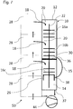
- the line may connect the outlet of the upstream pumping stage to more than one downstream pumping stage.
- all the downstream pumping stages can each be connected to the outlet of the upstream pumping stage via a further inlet.
- An extending between the pump chamber and housing line offers the advantage of a compact pump design. Additional external gas lines omitted, which in particular the handling of the pump is facilitated.
- generally known types of pumps can be used whose housing is suitable for providing a corresponding line.
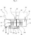
- the line which is connected to the outlet of the upstream pumping stage extends outside the pump housing.
- the outlet and / or the further inlet is then preferably a flange with which a releasable connection to the conduit can be made.
- the line is, for example, a pipe and / or a hose, in particular a corrugated hose.
- the conduit may be delimited by an outer wall of the housing and a component mounted on the outer wall, which is in particular made of the same or a similar material as the housing.
- the component may itself be formed like a box.
- the conduit extending outside the housing may be formed by a channel formed in a metal block.
- the metal block can be firmly screwed to the pump housing, whereby the line can be sealed particularly reliable.
- the metal block is connected to the outlet and / or the further inlet using known, standardized seals, ie, attached to the pump housing so as to form one or more conventional flange connections.
- the metal block is made of aluminum.
- a conduit extending outside the housing has the advantage that the flow path defined by the conduit can be varied in a vacuum pump with more than two pump stages. If all or at least most of the downstream pumping stages have an additional inlet and all or at least the most upstream pumping stages have an outlet, any desired connections can be made between the pumping stages.
- the vacuum pump according to the invention can be adapted in this way to the type of recipient as well as to the nature of the gas to be pumped.
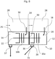
- a deflection means which does not return the flow path of the gas to be pumped after leaving the pump chamber into this, preferably comprises an outlet of the upstream pumping stage, to which an external device can be connected.
- the external device preferably comprises a backing pump.
- connection between the outlet and the external device is e.g. through pipes and / or hoses, in particular corrugated hoses.
- the outlet of the upstream pumping stage is assigned a molecular pumping stage, for example a Siegbahn and / or Holweck pumping stage. This causes high compression in close proximity to the outlet, allowing the gas to be pumped to be expelled at a higher pressure. It can be provided that all outlets of the pump is assigned a molecular pumping stage.
- Particularly preferred embodiments of the vacuum pump according to the invention comprise deflection means, which both lead out of the pump chamber Define flow path and at least include a partition, as described above.
- the invention also relates to a vacuum system comprising a device to be evacuated several chambers and at least one vacuum pump according to the invention, wherein the chambers are arranged one behind the other and each having a gas outlet which is connected in pumping operation with an inlet of one of the pumping stages of the vacuum pump.
- the downstream pumping stage 16b comprises, in addition to the turbomolecular pumping stage, a molecular pumping stage 26, which is in particular a Holweck pumping stage.
- the two pumping stages 16a and 16b each have an inlet 18 with an inlet region 20, wherein each inlet 18 is associated with an area to be evacuated.
- the flow direction or an inventively provided flow path 15 of the gas to be evacuated are indicated by arrows.
- the successive pump stages 16a and 16b are separated by a partition wall 30.
- the rotor shaft 22 extends to form a gap 32 through an opening in the partition wall 30 therethrough.
- the flow path 15 of the gas to be pumped passes through the gap 32. As a result, a direct onflow of the inlet region 20 of the downstream pumping stage 16b is avoided.
- Fig. 2a shows an enlarged cross-sectional view of the partition wall 30 in the region of its opening.
- the partition wall 30 is extended axially into the downstream pumping stage (on the left of the partition wall 30).
- the extension is realized by a mounted on the partition 30 hollow cylinder 31, which surrounds the rotor shaft 22.
- the flow path of the gas to be evacuated is with a Arrow indicated. If you transfer the detail view according to Fig. 2a on Fig. 1 , it becomes clear that the inlet region 20 assigned to the downstream pumping stage 16b experiences an even better shielding due to the extension.
- Fig. 2b shows an enlarged cross-sectional view of the partition wall 30 in the region of its opening according to another embodiment.
- the gap 32 is associated with a flow resistance 34 which is mounted on the rotor shaft 22 on the side of an upstream pumping stage.
- a flow resistance 34 which is mounted on the rotor shaft 22 on the side of an upstream pumping stage.
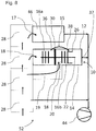
- the partition wall 30 arranged between two pumping stages is intended to be essentially gas-tight. This is the case, in particular, if a further deflecting means is provided which defines a flow path leading out of the pump chamber (cf. Fig. 3 to 8 ).
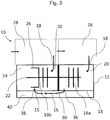
- Fig. 3 shows a vacuum pump 10, in contrast to the vacuum pump according to Fig. 1 a channel 40 which is arranged between the housing 12 and the pump chamber 14 parallel to the rotor shaft 22.
- the channel 40 is separated by a static component 13 of the housing 12 from the pump chamber 14 substantially gas-tight.
- the channel 40 connects the outlet 36 of the upstream pumping stage 16a with another inlet 38 of the downstream pumping stage 16b.
- the further inlet 38 is arranged in the immediate vicinity of a molecular pump stage 26. The increased compression at this point prevents a backflow of the gas to be pumped into the channel 40.
- the flow path 15 of the gas to be pumped by arrows is thus led out of the pump chamber 14 and fed back downstream of the pumping chamber 14 at the level of the downstream pumping stage 16b.
- the influx of the pumping stage 16b associated inlet portion 20 is thus avoided.
Landscapes
- Engineering & Computer Science (AREA)
- Mechanical Engineering (AREA)
- General Engineering & Computer Science (AREA)
- Non-Positive Displacement Air Blowers (AREA)
Claims (13)
- Pompe à vide, en particulier pompe turbomoléculaire, comportant :un boîtier (12) qui entoure une chambre de pompe (14) pour un gaz à pomper, dans laquelle sont agencés plusieurs étages de pompage (16a, 16b) branchés les uns derrière les autres le long d'un axe et agissant dans la même direction,dans laquelleles étapes de pompage (16a, 16b) présentent chacun une entrée (18) ayant une zone d'entrée (20) située à l'intérieur du boîtier (12),caractérisée en ce queles entrées (18) sont disposées chacune en amont de l'étage de pompage (16a, 16b) et il n'est pas prévu d'autre entrée entre les entrées (18), etil est prévu au moins un moyen de déviation (30, 34, 38, 40, 42) qui assure au moins un chemin d'écoulement (15) pour le gaz à pomper, qui part d'un étage de pompage (16a) disposé en amont et qui mène en éloignement de la zone d'entrée (20) d'un étage de pompage (16b) disposé en aval.
- Pompe à vide selon la revendication 1,
dans laquelle
le moyen de déviation comprend une cloison de séparation (30) disposée entre deux étages de pompage (16a, 16b), à travers laquelle s'étend un arbre de rotor (22) associé aux étages de pompage (16a, 16b). - Pompe à vide selon la revendication 2,
dans laquelle
l'arbre de rotor (22) traverse une ouverture dans la cloison de séparation (30) en réalisant une fente (32). - Pompe à vide selon la revendication 3,
dans laquelle
le chemin d'écoulement (15) s'étend à travers la fente (32). - Pompe à vide selon la revendication 3 ou 4,
dans laquelle
au niveau de l'arbre de rotor (22), la cloison de séparation (30) est prolongée axialement jusque dans l'étage de pompage (16b) disposé en aval. - Pompe à vide selon l'une des revendications 3 à 5,
dans laquelle
la fente (32) est délimitée par des structures actives en pompage. - Pompe à vide selon l'une des revendications 3 à 6,
dans laquelle
une résistance à l'écoulement (34) est associée à la fente (32) à titre de moyen de déviation. - Pompe à vide selon l'une des revendications précédentes,
dans laquelle
le moyen de déviation définit un chemin d'écoulement menant hors de la chambre de pompe (14). - Pompe à vide selon l'une des revendications précédentes,
dans laquelle
le moyen de déviation présente une sortie (36) de l'étage de pompage (16a) disposé en amont, qui est reliée à une autre entrée (38) de l'étage de pompage (16b) disposé en aval par une conduite (40, 42) et/ou à laquelle peut être raccordé un dispositif externe. - Pompe à vide selon la revendication 9,
dans laquelle
la conduite (40) s'étend à l'intérieur du boîtier (12) et à l'extérieur de la chambre de pompe (14). - Pompe à vide selon la revendication 9,
dans laquelle
la conduite (42) s'étend à l'extérieur du boîtier (12). - Pompe à vide selon l'une des revendications 9 à 11,
dans laquelle
au moins un étage de pompage moléculaire (26) est associé à la sortie (36). - Système à vide comportant un dispositif ayant plusieurs chambres (28) à évacuer et au moins une pompe à vide (10) selon l'une des revendications précédentes,
dans lequel
les chambres (28) sont disposées les unes derrière les autres et présentent chacune une sortie de gaz qui, pendant le fonctionnement de pompage, est reliée à une entrée (18) de l'un des étages de pompage (16a, 16b, 16c) de la pompe à vide (10).
Priority Applications (2)
| Application Number | Priority Date | Filing Date | Title |
|---|---|---|---|
| EP15164305.3A EP3085963B1 (fr) | 2015-04-20 | 2015-04-20 | Pompe à vide |
| JP2016083605A JP6225213B2 (ja) | 2015-04-20 | 2016-04-19 | 真空ポンプ |
Applications Claiming Priority (1)
| Application Number | Priority Date | Filing Date | Title |
|---|---|---|---|
| EP15164305.3A EP3085963B1 (fr) | 2015-04-20 | 2015-04-20 | Pompe à vide |
Publications (2)
| Publication Number | Publication Date |
|---|---|
| EP3085963A1 EP3085963A1 (fr) | 2016-10-26 |
| EP3085963B1 true EP3085963B1 (fr) | 2019-09-04 |
Family
ID=52987975
Family Applications (1)
| Application Number | Title | Priority Date | Filing Date |
|---|---|---|---|
| EP15164305.3A Active EP3085963B1 (fr) | 2015-04-20 | 2015-04-20 | Pompe à vide |
Country Status (2)
| Country | Link |
|---|---|
| EP (1) | EP3085963B1 (fr) |
| JP (1) | JP6225213B2 (fr) |
Families Citing this family (4)
| Publication number | Priority date | Publication date | Assignee | Title |
|---|---|---|---|---|
| EP3767110B1 (fr) | 2019-07-15 | 2024-09-18 | Pfeiffer Vacuum Gmbh | Système sous vide |
| EP3767109B1 (fr) | 2019-07-15 | 2021-09-08 | Pfeiffer Vacuum Gmbh | Système à vide |
| EP3693610B1 (fr) * | 2020-01-27 | 2021-12-22 | Pfeiffer Vacuum Technology AG | Pompe à vide moléculaire |
| DE102023133450B3 (de) | 2023-11-29 | 2025-01-30 | Pfeiffer Vacuum Technology AG | Vorrichtung und Verfahren zur Lecksuche |
Family Cites Families (6)
| Publication number | Priority date | Publication date | Assignee | Title |
|---|---|---|---|---|
| DE4228313A1 (de) * | 1992-08-26 | 1994-03-03 | Leybold Ag | Gegenstrom-Lecksucher mit Hochvakuumpumpe |
| GB0322889D0 (en) * | 2003-09-30 | 2003-10-29 | Boc Group Plc | Vacuum pump |
| GB0411426D0 (en) * | 2004-05-21 | 2004-06-23 | Boc Group Plc | Pumping arrangement |
| GB0424199D0 (en) * | 2004-11-01 | 2004-12-01 | Boc Group Plc | Vacuum pump |
| GB0503946D0 (en) * | 2005-02-25 | 2005-04-06 | Boc Group Plc | Vacuum pump |
| DE102013109637A1 (de) * | 2013-09-04 | 2015-03-05 | Pfeiffer Vacuum Gmbh | Vakuumpumpe sowie Anordnung mit einer Vakuumpumpe |
-
2015
- 2015-04-20 EP EP15164305.3A patent/EP3085963B1/fr active Active
-
2016
- 2016-04-19 JP JP2016083605A patent/JP6225213B2/ja active Active
Non-Patent Citations (1)
| Title |
|---|
| None * |
Also Published As
| Publication number | Publication date |
|---|---|
| JP2016205392A (ja) | 2016-12-08 |
| JP6225213B2 (ja) | 2017-11-01 |
| EP3085963A1 (fr) | 2016-10-26 |
Similar Documents
| Publication | Publication Date | Title |
|---|---|---|
| EP3347598B1 (fr) | Ventilateur turbo avec élément de refroidissement | |
| DE602004008089T2 (de) | Vakuumpumpe | |
| EP2295812B1 (fr) | Récipient repliable | |
| EP1090231B2 (fr) | Pompe a vide rotative munie d'un chassis, d'un rotor et d'un carter, et dispositif pourvu d'une pompe a vide rotative de ce type | |
| EP2846044B1 (fr) | Pompe à vide et système doté d'une pompe à vide | |
| EP3085963A1 (fr) | Pompe à vide | |
| DE102016210701A1 (de) | Massenspektrometrischer Lecksucher mit Turbomolekularpumpe und Boosterpumpe auf gemeinsamer Welle | |
| EP2039941B1 (fr) | Pompe à vide | |
| EP1706645B1 (fr) | Pompe à vide à frottement à plusieurs étages | |
| EP3112688B2 (fr) | Pompe à vide à débit partagé et système à vide doté d'une pompe à débit partagé | |
| EP2133581B1 (fr) | Elément de liaison | |
| EP2975268B1 (fr) | Système à vide | |
| DE102008009715A1 (de) | Vakuumpump-System und Verwendung einer Mehrstufen-Vakuumpumpe | |
| EP2290242A2 (fr) | Pompe à vide | |
| EP2228540B1 (fr) | Agencement doté d'une pompe à vide | |
| CH677009A5 (fr) | ||
| WO2010097384A2 (fr) | Pompe à vide à plusieurs entrées | |
| WO2000058629A1 (fr) | Compresseur a conduit lateral | |
| WO2005124309A1 (fr) | Detecteur de fuites a sonde renifleuse | |
| DE202013010204U1 (de) | Multi-Inlet-Vakuumpumpe | |
| EP3112689B1 (fr) | Pompe à vide à debit partagé | |
| DE19901340B4 (de) | Reibungsvakuumpumpe mit Chassis, Rotor und Gehäuse sowie Einrichtung, ausgerüstet mit einer Reibungsvakuumpumpe dieser Art | |
| EP3296571B1 (fr) | Pompe à vide | |
| WO2010105908A1 (fr) | Pompe à vide à entrées multiples | |
| EP2886870B2 (fr) | Pompe à vide avec géométrie d'admission perfectionnée |
Legal Events
| Date | Code | Title | Description |
|---|---|---|---|
| PUAI | Public reference made under article 153(3) epc to a published international application that has entered the european phase |
Free format text: ORIGINAL CODE: 0009012 |
|
| AK | Designated contracting states |
Kind code of ref document: A1 Designated state(s): AL AT BE BG CH CY CZ DE DK EE ES FI FR GB GR HR HU IE IS IT LI LT LU LV MC MK MT NL NO PL PT RO RS SE SI SK SM TR |
|
| AX | Request for extension of the european patent |
Extension state: BA ME |
|
| STAA | Information on the status of an ep patent application or granted ep patent |
Free format text: STATUS: REQUEST FOR EXAMINATION WAS MADE |
|
| 17P | Request for examination filed |
Effective date: 20170418 |
|
| RBV | Designated contracting states (corrected) |
Designated state(s): AL AT BE BG CH CY CZ DE DK EE ES FI FR GB GR HR HU IE IS IT LI LT LU LV MC MK MT NL NO PL PT RO RS SE SI SK SM TR |
|
| GRAP | Despatch of communication of intention to grant a patent |
Free format text: ORIGINAL CODE: EPIDOSNIGR1 |
|
| STAA | Information on the status of an ep patent application or granted ep patent |
Free format text: STATUS: GRANT OF PATENT IS INTENDED |
|
| INTG | Intention to grant announced |
Effective date: 20190325 |
|
| GRAS | Grant fee paid |
Free format text: ORIGINAL CODE: EPIDOSNIGR3 |
|
| GRAA | (expected) grant |
Free format text: ORIGINAL CODE: 0009210 |
|
| STAA | Information on the status of an ep patent application or granted ep patent |
Free format text: STATUS: THE PATENT HAS BEEN GRANTED |
|
| AK | Designated contracting states |
Kind code of ref document: B1 Designated state(s): AL AT BE BG CH CY CZ DE DK EE ES FI FR GB GR HR HU IE IS IT LI LT LU LV MC MK MT NL NO PL PT RO RS SE SI SK SM TR |
|
| REG | Reference to a national code |
Ref country code: GB Ref legal event code: FG4D Free format text: NOT ENGLISH |
|
| REG | Reference to a national code |
Ref country code: CH Ref legal event code: EP |
|
| REG | Reference to a national code |
Ref country code: AT Ref legal event code: REF Ref document number: 1175724 Country of ref document: AT Kind code of ref document: T Effective date: 20190915 |
|
| REG | Reference to a national code |
Ref country code: DE Ref legal event code: R096 Ref document number: 502015010210 Country of ref document: DE |
|
| REG | Reference to a national code |
Ref country code: IE Ref legal event code: FG4D Free format text: LANGUAGE OF EP DOCUMENT: GERMAN |
|
| REG | Reference to a national code |
Ref country code: NL Ref legal event code: MP Effective date: 20190904 |
|
| REG | Reference to a national code |
Ref country code: LT Ref legal event code: MG4D |
|
| PG25 | Lapsed in a contracting state [announced via postgrant information from national office to epo] |
Ref country code: LT Free format text: LAPSE BECAUSE OF FAILURE TO SUBMIT A TRANSLATION OF THE DESCRIPTION OR TO PAY THE FEE WITHIN THE PRESCRIBED TIME-LIMIT Effective date: 20190904 Ref country code: SE Free format text: LAPSE BECAUSE OF FAILURE TO SUBMIT A TRANSLATION OF THE DESCRIPTION OR TO PAY THE FEE WITHIN THE PRESCRIBED TIME-LIMIT Effective date: 20190904 Ref country code: BG Free format text: LAPSE BECAUSE OF FAILURE TO SUBMIT A TRANSLATION OF THE DESCRIPTION OR TO PAY THE FEE WITHIN THE PRESCRIBED TIME-LIMIT Effective date: 20191204 Ref country code: HR Free format text: LAPSE BECAUSE OF FAILURE TO SUBMIT A TRANSLATION OF THE DESCRIPTION OR TO PAY THE FEE WITHIN THE PRESCRIBED TIME-LIMIT Effective date: 20190904 Ref country code: NO Free format text: LAPSE BECAUSE OF FAILURE TO SUBMIT A TRANSLATION OF THE DESCRIPTION OR TO PAY THE FEE WITHIN THE PRESCRIBED TIME-LIMIT Effective date: 20191204 Ref country code: FI Free format text: LAPSE BECAUSE OF FAILURE TO SUBMIT A TRANSLATION OF THE DESCRIPTION OR TO PAY THE FEE WITHIN THE PRESCRIBED TIME-LIMIT Effective date: 20190904 |
|
| PG25 | Lapsed in a contracting state [announced via postgrant information from national office to epo] |
Ref country code: RS Free format text: LAPSE BECAUSE OF FAILURE TO SUBMIT A TRANSLATION OF THE DESCRIPTION OR TO PAY THE FEE WITHIN THE PRESCRIBED TIME-LIMIT Effective date: 20190904 Ref country code: ES Free format text: LAPSE BECAUSE OF FAILURE TO SUBMIT A TRANSLATION OF THE DESCRIPTION OR TO PAY THE FEE WITHIN THE PRESCRIBED TIME-LIMIT Effective date: 20190904 Ref country code: GR Free format text: LAPSE BECAUSE OF FAILURE TO SUBMIT A TRANSLATION OF THE DESCRIPTION OR TO PAY THE FEE WITHIN THE PRESCRIBED TIME-LIMIT Effective date: 20191205 Ref country code: AL Free format text: LAPSE BECAUSE OF FAILURE TO SUBMIT A TRANSLATION OF THE DESCRIPTION OR TO PAY THE FEE WITHIN THE PRESCRIBED TIME-LIMIT Effective date: 20190904 Ref country code: LV Free format text: LAPSE BECAUSE OF FAILURE TO SUBMIT A TRANSLATION OF THE DESCRIPTION OR TO PAY THE FEE WITHIN THE PRESCRIBED TIME-LIMIT Effective date: 20190904 |
|
| PG25 | Lapsed in a contracting state [announced via postgrant information from national office to epo] |
Ref country code: RO Free format text: LAPSE BECAUSE OF FAILURE TO SUBMIT A TRANSLATION OF THE DESCRIPTION OR TO PAY THE FEE WITHIN THE PRESCRIBED TIME-LIMIT Effective date: 20190904 Ref country code: EE Free format text: LAPSE BECAUSE OF FAILURE TO SUBMIT A TRANSLATION OF THE DESCRIPTION OR TO PAY THE FEE WITHIN THE PRESCRIBED TIME-LIMIT Effective date: 20190904 Ref country code: NL Free format text: LAPSE BECAUSE OF FAILURE TO SUBMIT A TRANSLATION OF THE DESCRIPTION OR TO PAY THE FEE WITHIN THE PRESCRIBED TIME-LIMIT Effective date: 20190904 Ref country code: PL Free format text: LAPSE BECAUSE OF FAILURE TO SUBMIT A TRANSLATION OF THE DESCRIPTION OR TO PAY THE FEE WITHIN THE PRESCRIBED TIME-LIMIT Effective date: 20190904 Ref country code: PT Free format text: LAPSE BECAUSE OF FAILURE TO SUBMIT A TRANSLATION OF THE DESCRIPTION OR TO PAY THE FEE WITHIN THE PRESCRIBED TIME-LIMIT Effective date: 20200106 |
|
| PG25 | Lapsed in a contracting state [announced via postgrant information from national office to epo] |
Ref country code: SK Free format text: LAPSE BECAUSE OF FAILURE TO SUBMIT A TRANSLATION OF THE DESCRIPTION OR TO PAY THE FEE WITHIN THE PRESCRIBED TIME-LIMIT Effective date: 20190904 Ref country code: IS Free format text: LAPSE BECAUSE OF FAILURE TO SUBMIT A TRANSLATION OF THE DESCRIPTION OR TO PAY THE FEE WITHIN THE PRESCRIBED TIME-LIMIT Effective date: 20200224 Ref country code: SM Free format text: LAPSE BECAUSE OF FAILURE TO SUBMIT A TRANSLATION OF THE DESCRIPTION OR TO PAY THE FEE WITHIN THE PRESCRIBED TIME-LIMIT Effective date: 20190904 |
|
| REG | Reference to a national code |
Ref country code: DE Ref legal event code: R097 Ref document number: 502015010210 Country of ref document: DE |
|
| PLBE | No opposition filed within time limit |
Free format text: ORIGINAL CODE: 0009261 |
|
| STAA | Information on the status of an ep patent application or granted ep patent |
Free format text: STATUS: NO OPPOSITION FILED WITHIN TIME LIMIT |
|
| PG2D | Information on lapse in contracting state deleted |
Ref country code: IS |
|
| PG25 | Lapsed in a contracting state [announced via postgrant information from national office to epo] |
Ref country code: DK Free format text: LAPSE BECAUSE OF FAILURE TO SUBMIT A TRANSLATION OF THE DESCRIPTION OR TO PAY THE FEE WITHIN THE PRESCRIBED TIME-LIMIT Effective date: 20190904 Ref country code: IS Free format text: LAPSE BECAUSE OF FAILURE TO SUBMIT A TRANSLATION OF THE DESCRIPTION OR TO PAY THE FEE WITHIN THE PRESCRIBED TIME-LIMIT Effective date: 20200105 |
|
| 26N | No opposition filed |
Effective date: 20200605 |
|
| PG25 | Lapsed in a contracting state [announced via postgrant information from national office to epo] |
Ref country code: SI Free format text: LAPSE BECAUSE OF FAILURE TO SUBMIT A TRANSLATION OF THE DESCRIPTION OR TO PAY THE FEE WITHIN THE PRESCRIBED TIME-LIMIT Effective date: 20190904 |
|
| PG25 | Lapsed in a contracting state [announced via postgrant information from national office to epo] |
Ref country code: MC Free format text: LAPSE BECAUSE OF FAILURE TO SUBMIT A TRANSLATION OF THE DESCRIPTION OR TO PAY THE FEE WITHIN THE PRESCRIBED TIME-LIMIT Effective date: 20190904 |
|
| REG | Reference to a national code |
Ref country code: CH Ref legal event code: PL |
|
| PG25 | Lapsed in a contracting state [announced via postgrant information from national office to epo] |
Ref country code: CH Free format text: LAPSE BECAUSE OF NON-PAYMENT OF DUE FEES Effective date: 20200430 Ref country code: LI Free format text: LAPSE BECAUSE OF NON-PAYMENT OF DUE FEES Effective date: 20200430 Ref country code: FR Free format text: LAPSE BECAUSE OF NON-PAYMENT OF DUE FEES Effective date: 20200430 Ref country code: LU Free format text: LAPSE BECAUSE OF NON-PAYMENT OF DUE FEES Effective date: 20200420 |
|
| REG | Reference to a national code |
Ref country code: BE Ref legal event code: MM Effective date: 20200430 |
|
| PG25 | Lapsed in a contracting state [announced via postgrant information from national office to epo] |
Ref country code: BE Free format text: LAPSE BECAUSE OF NON-PAYMENT OF DUE FEES Effective date: 20200430 |
|
| PG25 | Lapsed in a contracting state [announced via postgrant information from national office to epo] |
Ref country code: IE Free format text: LAPSE BECAUSE OF NON-PAYMENT OF DUE FEES Effective date: 20200420 |
|
| REG | Reference to a national code |
Ref country code: AT Ref legal event code: MM01 Ref document number: 1175724 Country of ref document: AT Kind code of ref document: T Effective date: 20200420 |
|
| PG25 | Lapsed in a contracting state [announced via postgrant information from national office to epo] |
Ref country code: AT Free format text: LAPSE BECAUSE OF NON-PAYMENT OF DUE FEES Effective date: 20200420 |
|
| PG25 | Lapsed in a contracting state [announced via postgrant information from national office to epo] |
Ref country code: TR Free format text: LAPSE BECAUSE OF FAILURE TO SUBMIT A TRANSLATION OF THE DESCRIPTION OR TO PAY THE FEE WITHIN THE PRESCRIBED TIME-LIMIT Effective date: 20190904 Ref country code: MT Free format text: LAPSE BECAUSE OF FAILURE TO SUBMIT A TRANSLATION OF THE DESCRIPTION OR TO PAY THE FEE WITHIN THE PRESCRIBED TIME-LIMIT Effective date: 20190904 Ref country code: CY Free format text: LAPSE BECAUSE OF FAILURE TO SUBMIT A TRANSLATION OF THE DESCRIPTION OR TO PAY THE FEE WITHIN THE PRESCRIBED TIME-LIMIT Effective date: 20190904 |
|
| PG25 | Lapsed in a contracting state [announced via postgrant information from national office to epo] |
Ref country code: MK Free format text: LAPSE BECAUSE OF FAILURE TO SUBMIT A TRANSLATION OF THE DESCRIPTION OR TO PAY THE FEE WITHIN THE PRESCRIBED TIME-LIMIT Effective date: 20190904 |
|
| PGFP | Annual fee paid to national office [announced via postgrant information from national office to epo] |
Ref country code: DE Payment date: 20250625 Year of fee payment: 11 |
|
| PGFP | Annual fee paid to national office [announced via postgrant information from national office to epo] |
Ref country code: GB Payment date: 20250423 Year of fee payment: 11 |
|
| PGFP | Annual fee paid to national office [announced via postgrant information from national office to epo] |
Ref country code: IT Payment date: 20250424 Year of fee payment: 11 |
|
| PGFP | Annual fee paid to national office [announced via postgrant information from national office to epo] |
Ref country code: CZ Payment date: 20250414 Year of fee payment: 11 |