EP2229862A2 - Aspirateur doté d'un élément de connexion électrique - Google Patents
Aspirateur doté d'un élément de connexion électrique Download PDFInfo
- Publication number
- EP2229862A2 EP2229862A2 EP20100153955 EP10153955A EP2229862A2 EP 2229862 A2 EP2229862 A2 EP 2229862A2 EP 20100153955 EP20100153955 EP 20100153955 EP 10153955 A EP10153955 A EP 10153955A EP 2229862 A2 EP2229862 A2 EP 2229862A2
- Authority
- EP
- European Patent Office
- Prior art keywords
- vacuum cleaner
- contacts
- fan
- supply device
- group
- Prior art date
- Legal status (The legal status is an assumption and is not a legal conclusion. Google has not performed a legal analysis and makes no representation as to the accuracy of the status listed.)
- Granted
Links
Images
Classifications
-
- A—HUMAN NECESSITIES
- A47—FURNITURE; DOMESTIC ARTICLES OR APPLIANCES; COFFEE MILLS; SPICE MILLS; SUCTION CLEANERS IN GENERAL
- A47L—DOMESTIC WASHING OR CLEANING; SUCTION CLEANERS IN GENERAL
- A47L9/00—Details or accessories of suction cleaners, e.g. mechanical means for controlling the suction or for effecting pulsating action; Storing devices specially adapted to suction cleaners or parts thereof; Carrying-vehicles specially adapted for suction cleaners
- A47L9/28—Installation of the electric equipment, e.g. adaptation or attachment to the suction cleaner; Controlling suction cleaners by electric means
-
- A—HUMAN NECESSITIES
- A47—FURNITURE; DOMESTIC ARTICLES OR APPLIANCES; COFFEE MILLS; SPICE MILLS; SUCTION CLEANERS IN GENERAL
- A47L—DOMESTIC WASHING OR CLEANING; SUCTION CLEANERS IN GENERAL
- A47L9/00—Details or accessories of suction cleaners, e.g. mechanical means for controlling the suction or for effecting pulsating action; Storing devices specially adapted to suction cleaners or parts thereof; Carrying-vehicles specially adapted for suction cleaners
- A47L9/28—Installation of the electric equipment, e.g. adaptation or attachment to the suction cleaner; Controlling suction cleaners by electric means
- A47L9/2868—Arrangements for power supply of vacuum cleaners or the accessories thereof
Definitions
- the present invention relates to a vacuum cleaner having a fan room, which has a fan, a space adjacent to the fan room, which has a supply device, and an electrical connection element, which comprises a first and a second group of electrical contacts and power line elements, the contacts of the first and electrically interconnecting the second group, wherein the fan room and the space adjacent the fan room are connected to each other via an opening, and the contacts of the first group to the supply device in the space adjacent to the fan room, and the contacts of the second group to the fan in the Blower chamber are connected to electrically connect the supply device and the fan with each other.
- German Offenlegungsschrift is known from the prior art DE 102 41 588 A1 known, in which an air conditioning device is disclosed with a housing for receiving a circuit board of a control device.
- the cover is used for electrical contacting of a control unit and for connecting an air duct for the air conditioning.
- the lid can be used for simultaneously closing a plurality of cavities, and is hermetically sealed by plugging the respective plug.
- the pins of the connectors do not seal in the pin openings and therefore can be very easily inserted through the lid.
- WO 01/52359 A1 From the international writing WO 01/52359 A1 is known with a circuit board mechanically fixable and electrically contactable connector unit, which is particularly needed for actuators in motor vehicles.
- the plug-in unit can be contacted and fixed at a defined distance by means of non-positive elastic prestressing to the surface of a printed circuit board.
- the contact legs are soldered to the board.
- the Contact legs of the plug unit are kept free of mechanical fixing tasks.
- different thickness of the board is a constant contact level of contact paths of the plug unit and in particular their motor-side contact tongues when contacting them associated contact pins on a brush unit, which is arranged at the open end of a cup-shaped motor housing guaranteed.
- Vacuum cleaners are also known from the state of the art, in which two cables are struck on a circuit board and soldered firmly to the circuit board. Connectors are crimped on the two cables, which are contacted on two connector lugs on the fan. The cable is inserted into a slot in a partition wall between fan and cable drum space and must be subsequently fixed in order to avoid pinching between components. In addition, when passing the cable through the slot, difficulties arise in sealing the slot while the cable is being passed.
- the invention has for its object to provide a comparison with the prior art improved vacuum cleaner.
- an escape of air from the fan room in other rooms of the vacuum cleaner is to be avoided, and at the same time arranged in the fan room fan via an electrical line to be powered.
- the reliability of the electrical contacting of the fan should be ensured.
- a vacuum cleaner is understood to mean appliances powered by electrical energy to absorb dust, including both mains operated and battery or cordless appliances.
- a blower is the component of a vacuum cleaner to be understood, which is arranged by an electric drive, for example an electric motor, for generating the suction air flow in the vacuum cleaner.
- an electric drive for example an electric motor
- the fan on blades for generating a negative pressure
- an electric motor for driving the blades on.
- This overpressure can be increased in particular by filter devices, for example by HEPA filters on the air outlet of the vacuum cleaner.
- the air which flows past the electric motor after passing through the blades, can have a high temperature due to the ohmic heat generated during operation on the electric motor.
- a fan room and a room adjacent to the fan room are to be understood as spaces which are arranged in a vacuum cleaner housing.
- the flow of exhaust air from the fan room in an adjacent room when performing an electrical connection from the adjacent room can be largely avoided in the fan room or even substantially prevented completely.
- the sealing element closes the opening substantially airtight.
- a closure of the electrical feedthrough can prevent heating in the adjacent space by exhaust air, which has a high temperature after flowing through the drive motor of the blower. Since electrical supply lines can be installed in the adjacent room, it is an achievable advantage of the invention that safety problems caused by heating the adjacent room, such as short circuits, can be avoided.
- the sealing of unwanted openings in the fan room can contribute to a reduction of noise and thus to a reduction of the volume of the vacuum cleaner during operation.
- the space (4) adjacent to the blower compartment is a cable compartment for storing a power supply cable of the vacuum cleaner.
- the cable space is a cable drum space having a cable drum.
- An inventively preferred cable drum is arranged on a lower part of the vacuum cleaner described below.
- the connecting element can be mounted either after the fan and the cable drum or beforehand.
- the supply device is electrically connected to the cable drum in order to be able to electrically connect the cable drum to the connecting element.
- the power connection cable can be rolled up on the cable drum, which is particularly preferably electrically connected to the cable drum. In this way, an electrical connection of the blower via the cable, the supply device and the electrical connection element can be achieved in order to be able to supply the blower with power.
- the supply device is a circuit board and / or a transformer and / or a switch.
- the contacts of the first and / or second group are detachably connected.
- the contacts of the first and / or second group are formed as plug contacts.
- Preferred connections according to the invention of the blower and / or the supply device are designed as plug lugs. This can allow a reduction of the effort during assembly and / or disassembly of the connecting element.
- the contacts of the first and / or second group are plugged onto electrical connections of the blower and / or the supply device.
- the contacts of the first and / or second group are firmly connected to the blower and / or the supply device.
- the Contacts of the second group are connected to connections of the blower.
- connections of the blower, to which the contacts of the second group are connected are arranged outside the air flow. As a result, contamination of the contacts can be avoided by residual dust contained in the air flow.
- the connecting element is made of an elastically deformable material.
- An elastically deformable material is to be understood as meaning a material that can be brought into a shape different from the original form when force is applied, and returns to its original shape after the end of the force effect.
- a made of an elastically deformable material connecting element can advantageously absorb vibrations of the vacuum cleaner and / or the starting torque of the blower by a deformation and thus prevent deterioration of the contact quality. This improvement in the reliability of the contacts between blower and supply device can lead to a constant suction and thus to an improvement in the usability of the vacuum cleaner.
- the electrical connection element when installed in the vacuum automatically contacted the supply device and the fan, and thus finding the electrical connections can be automated. As a result, incorrect assembly and / or incorrect contacting can be avoided.
- the electrical connection element is firmly connected to the sealing element. This can prevent pinching by components or housing halves of the vacuum cleaner during assembly, since the connecting element and the sealing element can be arranged stationarily in the vacuum cleaner.
- the connecting element is at least partially made of plastic, particularly preferably made of elastically deformable plastic.
- the connecting element that comprises the sealing element is a contact bridge.
- Under a contact bridge is an elastically deformable component to understand, which can automatically return to the original position after a load by a force. This can advantageously be achieved that vibrations and the starting torque of the fan does not lead to an impairment of the contact quality.
- the connecting element and the sealing element form an integrally manufactured component.
- the sealing element particularly preferably has a circumferential U-profile, which is particularly preferably made of soft 2K material. Particularly preferably, the U-profile is designed as a sealing lip. In this way it can be ensured that the opening is closed airtight, even with a deformation of the contact bridge or the connecting element, whereby the sealing between the fan chamber and adjacent space can be reliably ensured.
- a preferred contact bridge is at least partially made of plastic.
- the contact bridge consists at least partially of elastically deformable plastic.
- the sealing properties of the sealing element can be further improved and shocks or other forces on the contact bridge can be better absorbed, whereby the contact quality of the contact bridge to the blower and / or to the supply device can be improved.
- the contact bridge on overmolded or applied power line elements.
- the contact bridge has injection-molded conductor tracks.
- the power line elements are metal bands or contact sheets. This can allow a simple and inexpensive production of the contact bridge.
- a lower part and a capsule surround the fan chamber.
- the individual components such as blower, electrical connection element with sealing element or supply device can be attached to the lower part to then connect the capsule to the lower part to close the fan room can.
- lower part and capsule can be formed as half-shells, which can form a substantially air-tight unit when joined.
- the fan room to ensure proper operation openings, such as to a dust collector unit or to an exhaust duct, which can lead the air back out of the vacuum cleaner.
- the fan chamber is substantially hermetically sealed. Between the fan room and adjacent room, the lower part and the half-shell can form a partition on which the opening is arranged.
- the opening is arranged on the lower part.
- the opening is particularly preferably a recess at the edge of the base. Under the edge of the lower part of the part of the lower part is to be understood, which touches the capsule when properly installed base and capsule.
- the electrical connection element and the sealing element are particularly preferably fixed via ribs in the lower part. In this way it can be achieved that the opening into which the electrical connection element and the sealing element can be inserted, is sealed by the capsule substantially airtight. In addition, this can be made possible by a simple assembly of the electrical connection element and the sealing element.
- the fan and the supply device can be mounted in order subsequently to be able to insert the electrical connection element and the sealing element into the opening. This can allow a correct position assembly of blower, supply device, connecting element and sealing element.
- the vacuum cleaner if the vacuum cleaner is installed as intended, it can be mounted from above, which can mean a particularly favorable position for the installation personnel.
- the fan and / or the supply device are mounted in the lower part. This may involve automatically contacting the ports of the blower and / or the utility, e.g. are formed as connector lugs, with the contacts of the contact bridge, the e.g. are designed as plug contacts allow, whereby fan and supply device can be automatically connected to each other automatically by the insertion of the connecting element and the sealing element in the opening. In addition, this can be avoided that contacts of the first and / or second group are plugged into incorrect connections of the fan and / or the supply device.
- the contacts of the first and / or second group conductive material with spring properties are particularly preferably, the contacts of the first and / or second group on resilient contact plates.
- the connection for example of the blower and / or the supply device, can be movably mounted in the contacts, whereby vibrations or other force influences are not permitted Impaired contact quality.
- the electrical connection element and / or the sealing element are made of an undeformable material.
- the present invention makes it possible to provide a vacuum cleaner with simple and inexpensive construction means, in which a mounting facilitation and cost savings in the electrical connection between a fan and a supply device, e.g. a circuit board can be reached. Furthermore, the invention enables a reduction of noise during operation. In addition, overheating in the adjacent room and impaired contact quality can be avoided.
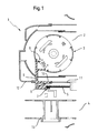
- a vacuum cleaner 1 is shown with a fan room 2, which has a fan 3, and a space 4 adjacent the fan room, which is a cable space for storing a power supply cable, and which has a supply device 5 and a cable drum 13.
- the supply device 5 can be electrically connected to the cable drum 13 via a connection, which is not shown for purposes of illustration.
- the vacuum cleaner 1 has an electrical connection element 6, the a first 7 and a second group of electrical contacts 8 and power line elements, which are not shown for illustrative purposes comprises.
- the power line elements electrically connect the contacts of the first 7 and the second group 8.
- the electrical connection element 6 has a sealing element 10, which closes an opening 9, via which the fan chamber 2 and the adjacent space 4 are connected to each other, substantially airtight.
- the air in the fan room 2 has been brought to a high temperature by the compression of the air but also by the ohmic heat of the electric motor driving the fan 3.
- the opening 9 is therefore airtight to close in order to avoid overheating in the adjacent space 4 and thus a security risk.
- the overpressure in the fan chamber 2 can be caused, for example, by a filter which is attached to the exhaust opening of the vacuum cleaner 1.
- the exhaust port may be located directly on the fan chamber 2, and is not shown for purposes of illustration.
- the blower 3 is electrically connected to the supply device 5 by connecting the contacts of the first group 7 to the supply device 5 in the adjacent room 4, and the contacts of the second group 8 to the blower 3 in the blower room 2 to the supply device. 5 and to electrically connect the blower 3 with each other.
- the contacts of the first 7 and the second group 8 are detachably connected to allow easy mounting or replacement of the electrical connection element 6.
- the connecting element 6 is made of an elastically deformable material.
- the contacts of the first 7 and the second group 8 conductive material with spring properties.
- the contacts of the first 7 and the second group 8 are plug-in contacts, the electrical connections of the fan and the supply device are designed as connector lugs. For illustrative purposes, the plug contacts and the connector lugs are not shown.
- the electrical connection element 6 is a contact bridge, which consists at least partially of plastic.
- a lower part 11 and a capsule 12 surround the blower compartment 2, wherein the opening 9, into which the contact bridge can be inserted during assembly, is arranged on the edge of the lower part 11 and has the shape of a rectangular indentation.
- the blower 3 can be electrically connected to a power supply via the electrical connection element 6 or the contact bridge, the supply device 5, the cable drum 13 and a not shown for reasons of representation power cable that can be rolled up on the cable drum 13.
- the invention facilitates the assembly of the electrical connection between a blower and a circuit board with simple and inexpensive structural means. At the same time, the operating noise can be reduced, overheating in the cable drum space avoided and good contact can be ensured.
Landscapes
- Engineering & Computer Science (AREA)
- Mechanical Engineering (AREA)
- Electric Vacuum Cleaner (AREA)
Applications Claiming Priority (1)
| Application Number | Priority Date | Filing Date | Title |
|---|---|---|---|
| DE200910001663 DE102009001663A1 (de) | 2009-03-19 | 2009-03-19 | Staubsauger mit elektrischem Verbindungselement |
Publications (3)
| Publication Number | Publication Date |
|---|---|
| EP2229862A2 true EP2229862A2 (fr) | 2010-09-22 |
| EP2229862A3 EP2229862A3 (fr) | 2014-10-15 |
| EP2229862B1 EP2229862B1 (fr) | 2016-04-20 |
Family
ID=42336270
Family Applications (1)
| Application Number | Title | Priority Date | Filing Date |
|---|---|---|---|
| EP10153955.9A Not-in-force EP2229862B1 (fr) | 2009-03-19 | 2010-02-18 | Aspirateur doté d'un élément de connexion électrique |
Country Status (2)
| Country | Link |
|---|---|
| EP (1) | EP2229862B1 (fr) |
| DE (1) | DE102009001663A1 (fr) |
Citations (2)
| Publication number | Priority date | Publication date | Assignee | Title |
|---|---|---|---|---|
| WO2001052359A1 (fr) | 2000-01-14 | 2001-07-19 | Siemens Aktiengesellschaft | Ensemble connecteur enfichable pouvant etre fixe mecaniquement en formant un angle et mis en contact electriquement avec une platine |
| DE10241588A1 (de) | 2002-09-05 | 2004-03-18 | Webasto Thermosysteme International Gmbh | Mobile Klimaeinrichtung, insbesondere Heizgerät |
Family Cites Families (2)
| Publication number | Priority date | Publication date | Assignee | Title |
|---|---|---|---|---|
| JP4266326B2 (ja) * | 2003-05-21 | 2009-05-20 | タイコエレクトロニクスアンプ株式会社 | 電気接続構造および電気接続システム |
| DE102007040951B4 (de) * | 2007-08-30 | 2013-01-10 | Miele & Cie. Kg | Staubsauger |
-
2009
- 2009-03-19 DE DE200910001663 patent/DE102009001663A1/de not_active Ceased
-
2010
- 2010-02-18 EP EP10153955.9A patent/EP2229862B1/fr not_active Not-in-force
Patent Citations (2)
| Publication number | Priority date | Publication date | Assignee | Title |
|---|---|---|---|---|
| WO2001052359A1 (fr) | 2000-01-14 | 2001-07-19 | Siemens Aktiengesellschaft | Ensemble connecteur enfichable pouvant etre fixe mecaniquement en formant un angle et mis en contact electriquement avec une platine |
| DE10241588A1 (de) | 2002-09-05 | 2004-03-18 | Webasto Thermosysteme International Gmbh | Mobile Klimaeinrichtung, insbesondere Heizgerät |
Also Published As
| Publication number | Publication date |
|---|---|
| EP2229862B1 (fr) | 2016-04-20 |
| EP2229862A3 (fr) | 2014-10-15 |
| DE102009001663A1 (de) | 2010-09-23 |
Similar Documents
| Publication | Publication Date | Title |
|---|---|---|
| DE112017003846T5 (de) | Leistungsanschluss für einen elektrischen Verbinder | |
| DE102013213336A1 (de) | Elektrischer steckverbinder und steckverbindersystem für ein elektro- oder hybridfahrzeug | |
| WO2007118798A2 (fr) | Dispositif de connexion électrique pour conducteur plat | |
| EP3143654B1 (fr) | Liaison entre deux modules de batterie d'un système de batterie | |
| DE102015110399A1 (de) | Motortemperaturüberwachung | |
| DE202018106353U1 (de) | Steckadapter zum Andocken an ein Magnetventil | |
| DE202013100297U1 (de) | Geräteanschlusssystem für Küchengeräte | |
| DE202013101698U1 (de) | Schutzleiterkontaktiersystem für Geräteanschlusssysteme elektrischer Geräte | |
| DE20318855U1 (de) | Anschlußmodul für Leistungsschalter | |
| DE102014110533B4 (de) | Anschlusssystem für elektrische Geräte | |
| EP2978075A2 (fr) | Connecteur, systeme de raccordement d'appareil dote de raccord de conducteur de protection pour appareils electriques et appareil electrique | |
| DE202014103376U1 (de) | Geräteanschlusssystem mit integriertem Schutzleiteranschluss für elektrische Geräte | |
| EP2904673B1 (fr) | Ventilateur doté d'un dispositif de raccordement électrique | |
| DE2700530C2 (de) | Elektrischer Motor mit am Klemmenkasten angebrachten Gleichrichterdioden | |
| EP2229862B1 (fr) | Aspirateur doté d'un élément de connexion électrique | |
| DE102020123097A1 (de) | Anschlussadapter für eine Antriebsvorrichtung | |
| DE202008004766U1 (de) | Codierbare Motoranschlusssteckkupplung | |
| DE102014102555B4 (de) | Elektrische Einrichtung mit Pendelkontakt | |
| DE102019114058A1 (de) | System umfassend eine Komponentenkodierung | |
| EP2924810A1 (fr) | Connecteur à fiches électrique doté de connecteur latéral | |
| DE202014103433U1 (de) | Anschlusssystem für elektrische Geräte | |
| DE202009003171U1 (de) | Ozongenerator | |
| AT517768A2 (de) | Überbrückungsvorrichtung für Zähleranschlussklemme | |
| DE102008062852A1 (de) | Verbindungsanordnung mit einem elektrischen Gerät, insbesondere ein Schalt- oder Schutzgerät und einem weiteren Bauteil | |
| DE102014110344A1 (de) | Geräteanschlusssystem mit integriertem Schutzleiteranschluss für elektrische Geräte |
Legal Events
| Date | Code | Title | Description |
|---|---|---|---|
| PUAI | Public reference made under article 153(3) epc to a published international application that has entered the european phase |
Free format text: ORIGINAL CODE: 0009012 |
|
| AK | Designated contracting states |
Kind code of ref document: A2 Designated state(s): AT BE BG CH CY CZ DE DK EE ES FI FR GB GR HR HU IE IS IT LI LT LU LV MC MK MT NL NO PL PT RO SE SI SK SM TR |
|
| AX | Request for extension of the european patent |
Extension state: AL BA RS |
|
| PUAL | Search report despatched |
Free format text: ORIGINAL CODE: 0009013 |
|
| AK | Designated contracting states |
Kind code of ref document: A3 Designated state(s): AT BE BG CH CY CZ DE DK EE ES FI FR GB GR HR HU IE IS IT LI LT LU LV MC MK MT NL NO PL PT RO SE SI SK SM TR |
|
| AX | Request for extension of the european patent |
Extension state: AL BA RS |
|
| RIC1 | Information provided on ipc code assigned before grant |
Ipc: A47L 9/28 20060101AFI20140908BHEP |
|
| RAP1 | Party data changed (applicant data changed or rights of an application transferred) |
Owner name: BSH HAUSGERAETE GMBH |
|
| 17P | Request for examination filed |
Effective date: 20150415 |
|
| RBV | Designated contracting states (corrected) |
Designated state(s): AT BE BG CH CY CZ DE DK EE ES FI FR GB GR HR HU IE IS IT LI LT LU LV MC MK MT NL NO PL PT RO SE SI SK SM TR |
|
| GRAP | Despatch of communication of intention to grant a patent |
Free format text: ORIGINAL CODE: EPIDOSNIGR1 |
|
| INTG | Intention to grant announced |
Effective date: 20151012 |
|
| GRAS | Grant fee paid |
Free format text: ORIGINAL CODE: EPIDOSNIGR3 |
|
| GRAA | (expected) grant |
Free format text: ORIGINAL CODE: 0009210 |
|
| AK | Designated contracting states |
Kind code of ref document: B1 Designated state(s): AT BE BG CH CY CZ DE DK EE ES FI FR GB GR HR HU IE IS IT LI LT LU LV MC MK MT NL NO PL PT RO SE SI SK SM TR |
|
| REG | Reference to a national code |
Ref country code: GB Ref legal event code: FG4D Free format text: NOT ENGLISH |
|
| REG | Reference to a national code |
Ref country code: CH Ref legal event code: EP |
|
| REG | Reference to a national code |
Ref country code: AT Ref legal event code: REF Ref document number: 791416 Country of ref document: AT Kind code of ref document: T Effective date: 20160515 |
|
| REG | Reference to a national code |
Ref country code: IE Ref legal event code: FG4D Free format text: LANGUAGE OF EP DOCUMENT: GERMAN |
|
| REG | Reference to a national code |
Ref country code: DE Ref legal event code: R096 Ref document number: 502010011465 Country of ref document: DE |
|
| REG | Reference to a national code |
Ref country code: LT Ref legal event code: MG4D |
|
| REG | Reference to a national code |
Ref country code: NL Ref legal event code: MP Effective date: 20160420 |
|
| PG25 | Lapsed in a contracting state [announced via postgrant information from national office to epo] |
Ref country code: NL Free format text: LAPSE BECAUSE OF FAILURE TO SUBMIT A TRANSLATION OF THE DESCRIPTION OR TO PAY THE FEE WITHIN THE PRESCRIBED TIME-LIMIT Effective date: 20160420 Ref country code: FI Free format text: LAPSE BECAUSE OF FAILURE TO SUBMIT A TRANSLATION OF THE DESCRIPTION OR TO PAY THE FEE WITHIN THE PRESCRIBED TIME-LIMIT Effective date: 20160420 Ref country code: NO Free format text: LAPSE BECAUSE OF FAILURE TO SUBMIT A TRANSLATION OF THE DESCRIPTION OR TO PAY THE FEE WITHIN THE PRESCRIBED TIME-LIMIT Effective date: 20160720 Ref country code: LT Free format text: LAPSE BECAUSE OF FAILURE TO SUBMIT A TRANSLATION OF THE DESCRIPTION OR TO PAY THE FEE WITHIN THE PRESCRIBED TIME-LIMIT Effective date: 20160420 Ref country code: PL Free format text: LAPSE BECAUSE OF FAILURE TO SUBMIT A TRANSLATION OF THE DESCRIPTION OR TO PAY THE FEE WITHIN THE PRESCRIBED TIME-LIMIT Effective date: 20160420 |
|
| PG25 | Lapsed in a contracting state [announced via postgrant information from national office to epo] |
Ref country code: PT Free format text: LAPSE BECAUSE OF FAILURE TO SUBMIT A TRANSLATION OF THE DESCRIPTION OR TO PAY THE FEE WITHIN THE PRESCRIBED TIME-LIMIT Effective date: 20160822 Ref country code: LV Free format text: LAPSE BECAUSE OF FAILURE TO SUBMIT A TRANSLATION OF THE DESCRIPTION OR TO PAY THE FEE WITHIN THE PRESCRIBED TIME-LIMIT Effective date: 20160420 Ref country code: HR Free format text: LAPSE BECAUSE OF FAILURE TO SUBMIT A TRANSLATION OF THE DESCRIPTION OR TO PAY THE FEE WITHIN THE PRESCRIBED TIME-LIMIT Effective date: 20160420 Ref country code: ES Free format text: LAPSE BECAUSE OF FAILURE TO SUBMIT A TRANSLATION OF THE DESCRIPTION OR TO PAY THE FEE WITHIN THE PRESCRIBED TIME-LIMIT Effective date: 20160420 Ref country code: GR Free format text: LAPSE BECAUSE OF FAILURE TO SUBMIT A TRANSLATION OF THE DESCRIPTION OR TO PAY THE FEE WITHIN THE PRESCRIBED TIME-LIMIT Effective date: 20160721 Ref country code: SE Free format text: LAPSE BECAUSE OF FAILURE TO SUBMIT A TRANSLATION OF THE DESCRIPTION OR TO PAY THE FEE WITHIN THE PRESCRIBED TIME-LIMIT Effective date: 20160420 |
|
| PG25 | Lapsed in a contracting state [announced via postgrant information from national office to epo] |
Ref country code: IT Free format text: LAPSE BECAUSE OF FAILURE TO SUBMIT A TRANSLATION OF THE DESCRIPTION OR TO PAY THE FEE WITHIN THE PRESCRIBED TIME-LIMIT Effective date: 20160420 |
|
| REG | Reference to a national code |
Ref country code: DE Ref legal event code: R097 Ref document number: 502010011465 Country of ref document: DE |
|
| PG25 | Lapsed in a contracting state [announced via postgrant information from national office to epo] |
Ref country code: SK Free format text: LAPSE BECAUSE OF FAILURE TO SUBMIT A TRANSLATION OF THE DESCRIPTION OR TO PAY THE FEE WITHIN THE PRESCRIBED TIME-LIMIT Effective date: 20160420 Ref country code: DK Free format text: LAPSE BECAUSE OF FAILURE TO SUBMIT A TRANSLATION OF THE DESCRIPTION OR TO PAY THE FEE WITHIN THE PRESCRIBED TIME-LIMIT Effective date: 20160420 Ref country code: RO Free format text: LAPSE BECAUSE OF FAILURE TO SUBMIT A TRANSLATION OF THE DESCRIPTION OR TO PAY THE FEE WITHIN THE PRESCRIBED TIME-LIMIT Effective date: 20160420 Ref country code: EE Free format text: LAPSE BECAUSE OF FAILURE TO SUBMIT A TRANSLATION OF THE DESCRIPTION OR TO PAY THE FEE WITHIN THE PRESCRIBED TIME-LIMIT Effective date: 20160420 Ref country code: CZ Free format text: LAPSE BECAUSE OF FAILURE TO SUBMIT A TRANSLATION OF THE DESCRIPTION OR TO PAY THE FEE WITHIN THE PRESCRIBED TIME-LIMIT Effective date: 20160420 |
|
| REG | Reference to a national code |
Ref country code: FR Ref legal event code: PLFP Year of fee payment: 8 |
|
| PLBE | No opposition filed within time limit |
Free format text: ORIGINAL CODE: 0009261 |
|
| STAA | Information on the status of an ep patent application or granted ep patent |
Free format text: STATUS: NO OPPOSITION FILED WITHIN TIME LIMIT |
|
| PG25 | Lapsed in a contracting state [announced via postgrant information from national office to epo] |
Ref country code: SM Free format text: LAPSE BECAUSE OF FAILURE TO SUBMIT A TRANSLATION OF THE DESCRIPTION OR TO PAY THE FEE WITHIN THE PRESCRIBED TIME-LIMIT Effective date: 20160420 |
|
| 26N | No opposition filed |
Effective date: 20170123 |
|
| PG25 | Lapsed in a contracting state [announced via postgrant information from national office to epo] |
Ref country code: BE Free format text: LAPSE BECAUSE OF NON-PAYMENT OF DUE FEES Effective date: 20170228 Ref country code: SI Free format text: LAPSE BECAUSE OF FAILURE TO SUBMIT A TRANSLATION OF THE DESCRIPTION OR TO PAY THE FEE WITHIN THE PRESCRIBED TIME-LIMIT Effective date: 20160420 |
|
| PG25 | Lapsed in a contracting state [announced via postgrant information from national office to epo] |
Ref country code: MC Free format text: LAPSE BECAUSE OF FAILURE TO SUBMIT A TRANSLATION OF THE DESCRIPTION OR TO PAY THE FEE WITHIN THE PRESCRIBED TIME-LIMIT Effective date: 20160420 |
|
| REG | Reference to a national code |
Ref country code: CH Ref legal event code: PL |
|
| PG25 | Lapsed in a contracting state [announced via postgrant information from national office to epo] |
Ref country code: LI Free format text: LAPSE BECAUSE OF NON-PAYMENT OF DUE FEES Effective date: 20170228 Ref country code: CH Free format text: LAPSE BECAUSE OF NON-PAYMENT OF DUE FEES Effective date: 20170228 |
|
| REG | Reference to a national code |
Ref country code: IE Ref legal event code: MM4A |
|
| PG25 | Lapsed in a contracting state [announced via postgrant information from national office to epo] |
Ref country code: LU Free format text: LAPSE BECAUSE OF NON-PAYMENT OF DUE FEES Effective date: 20170218 |
|
| REG | Reference to a national code |
Ref country code: FR Ref legal event code: PLFP Year of fee payment: 9 Ref country code: BE Ref legal event code: MM Effective date: 20170228 |
|
| PG25 | Lapsed in a contracting state [announced via postgrant information from national office to epo] |
Ref country code: IE Free format text: LAPSE BECAUSE OF NON-PAYMENT OF DUE FEES Effective date: 20170218 |
|
| REG | Reference to a national code |
Ref country code: AT Ref legal event code: MM01 Ref document number: 791416 Country of ref document: AT Kind code of ref document: T Effective date: 20170218 |
|
| PG25 | Lapsed in a contracting state [announced via postgrant information from national office to epo] |
Ref country code: AT Free format text: LAPSE BECAUSE OF NON-PAYMENT OF DUE FEES Effective date: 20170218 |
|
| PG25 | Lapsed in a contracting state [announced via postgrant information from national office to epo] |
Ref country code: MT Free format text: LAPSE BECAUSE OF FAILURE TO SUBMIT A TRANSLATION OF THE DESCRIPTION OR TO PAY THE FEE WITHIN THE PRESCRIBED TIME-LIMIT Effective date: 20160420 |
|
| PGFP | Annual fee paid to national office [announced via postgrant information from national office to epo] |
Ref country code: GB Payment date: 20190221 Year of fee payment: 10 |
|
| PGFP | Annual fee paid to national office [announced via postgrant information from national office to epo] |
Ref country code: FR Payment date: 20190221 Year of fee payment: 10 |
|
| PG25 | Lapsed in a contracting state [announced via postgrant information from national office to epo] |
Ref country code: HU Free format text: LAPSE BECAUSE OF FAILURE TO SUBMIT A TRANSLATION OF THE DESCRIPTION OR TO PAY THE FEE WITHIN THE PRESCRIBED TIME-LIMIT; INVALID AB INITIO Effective date: 20100218 |
|
| PG25 | Lapsed in a contracting state [announced via postgrant information from national office to epo] |
Ref country code: BG Free format text: LAPSE BECAUSE OF FAILURE TO SUBMIT A TRANSLATION OF THE DESCRIPTION OR TO PAY THE FEE WITHIN THE PRESCRIBED TIME-LIMIT Effective date: 20160420 |
|
| PG25 | Lapsed in a contracting state [announced via postgrant information from national office to epo] |
Ref country code: CY Free format text: LAPSE BECAUSE OF NON-PAYMENT OF DUE FEES Effective date: 20160420 |
|
| PG25 | Lapsed in a contracting state [announced via postgrant information from national office to epo] |
Ref country code: MK Free format text: LAPSE BECAUSE OF FAILURE TO SUBMIT A TRANSLATION OF THE DESCRIPTION OR TO PAY THE FEE WITHIN THE PRESCRIBED TIME-LIMIT Effective date: 20160420 |
|
| PG25 | Lapsed in a contracting state [announced via postgrant information from national office to epo] |
Ref country code: TR Free format text: LAPSE BECAUSE OF FAILURE TO SUBMIT A TRANSLATION OF THE DESCRIPTION OR TO PAY THE FEE WITHIN THE PRESCRIBED TIME-LIMIT Effective date: 20160420 |
|
| PG25 | Lapsed in a contracting state [announced via postgrant information from national office to epo] |
Ref country code: IS Free format text: LAPSE BECAUSE OF FAILURE TO SUBMIT A TRANSLATION OF THE DESCRIPTION OR TO PAY THE FEE WITHIN THE PRESCRIBED TIME-LIMIT Effective date: 20160820 |
|
| GBPC | Gb: european patent ceased through non-payment of renewal fee |
Effective date: 20200218 |
|
| PG25 | Lapsed in a contracting state [announced via postgrant information from national office to epo] |
Ref country code: GB Free format text: LAPSE BECAUSE OF NON-PAYMENT OF DUE FEES Effective date: 20200218 Ref country code: FR Free format text: LAPSE BECAUSE OF NON-PAYMENT OF DUE FEES Effective date: 20200229 |
|
| PGFP | Annual fee paid to national office [announced via postgrant information from national office to epo] |
Ref country code: DE Payment date: 20230228 Year of fee payment: 14 |
|
| P01 | Opt-out of the competence of the unified patent court (upc) registered |
Effective date: 20230504 |
|
| REG | Reference to a national code |
Ref country code: DE Ref legal event code: R119 Ref document number: 502010011465 Country of ref document: DE |
|
| PG25 | Lapsed in a contracting state [announced via postgrant information from national office to epo] |
Ref country code: DE Free format text: LAPSE BECAUSE OF NON-PAYMENT OF DUE FEES Effective date: 20240903 |
|
| PG25 | Lapsed in a contracting state [announced via postgrant information from national office to epo] |
Ref country code: DE Free format text: LAPSE BECAUSE OF NON-PAYMENT OF DUE FEES Effective date: 20240903 |