EP2978075A2 - Connecteur, systeme de raccordement d'appareil dote de raccord de conducteur de protection pour appareils electriques et appareil electrique - Google Patents
Connecteur, systeme de raccordement d'appareil dote de raccord de conducteur de protection pour appareils electriques et appareil electrique Download PDFInfo
- Publication number
- EP2978075A2 EP2978075A2 EP15172422.6A EP15172422A EP2978075A2 EP 2978075 A2 EP2978075 A2 EP 2978075A2 EP 15172422 A EP15172422 A EP 15172422A EP 2978075 A2 EP2978075 A2 EP 2978075A2
- Authority
- EP
- European Patent Office
- Prior art keywords
- clamping spring
- power contact
- housing
- protective conductor
- connection
- Prior art date
- Legal status (The legal status is an assumption and is not a legal conclusion. Google has not performed a legal analysis and makes no representation as to the accuracy of the status listed.)
- Granted
Links
Images



Classifications
-
- H—ELECTRICITY
- H01—ELECTRIC ELEMENTS
- H01R—ELECTRICALLY-CONDUCTIVE CONNECTIONS; STRUCTURAL ASSOCIATIONS OF A PLURALITY OF MUTUALLY-INSULATED ELECTRICAL CONNECTING ELEMENTS; COUPLING DEVICES; CURRENT COLLECTORS
- H01R13/00—Details of coupling devices of the kinds covered by groups H01R12/70 or H01R24/00 - H01R33/00
- H01R13/73—Means for mounting coupling parts to apparatus or structures, e.g. to a wall
- H01R13/74—Means for mounting coupling parts in openings of a panel
-
- H—ELECTRICITY
- H01—ELECTRIC ELEMENTS
- H01R—ELECTRICALLY-CONDUCTIVE CONNECTIONS; STRUCTURAL ASSOCIATIONS OF A PLURALITY OF MUTUALLY-INSULATED ELECTRICAL CONNECTING ELEMENTS; COUPLING DEVICES; CURRENT COLLECTORS
- H01R13/00—Details of coupling devices of the kinds covered by groups H01R12/70 or H01R24/00 - H01R33/00
- H01R13/648—Protective earth or shield arrangements on coupling devices, e.g. anti-static shielding
- H01R13/652—Protective earth or shield arrangements on coupling devices, e.g. anti-static shielding with earth pin, blade or socket
-
- H—ELECTRICITY
- H01—ELECTRIC ELEMENTS
- H01R—ELECTRICALLY-CONDUCTIVE CONNECTIONS; STRUCTURAL ASSOCIATIONS OF A PLURALITY OF MUTUALLY-INSULATED ELECTRICAL CONNECTING ELEMENTS; COUPLING DEVICES; CURRENT COLLECTORS
- H01R24/00—Two-part coupling devices, or either of their cooperating parts, characterised by their overall structure
- H01R24/76—Two-part coupling devices, or either of their cooperating parts, characterised by their overall structure with sockets, clips or analogous contacts and secured to apparatus or structure, e.g. to a wall
- H01R24/78—Two-part coupling devices, or either of their cooperating parts, characterised by their overall structure with sockets, clips or analogous contacts and secured to apparatus or structure, e.g. to a wall with additional earth or shield contacts
-
- H—ELECTRICITY
- H01—ELECTRIC ELEMENTS
- H01R—ELECTRICALLY-CONDUCTIVE CONNECTIONS; STRUCTURAL ASSOCIATIONS OF A PLURALITY OF MUTUALLY-INSULATED ELECTRICAL CONNECTING ELEMENTS; COUPLING DEVICES; CURRENT COLLECTORS
- H01R4/00—Electrically-conductive connections between two or more conductive members in direct contact, i.e. touching one another; Means for effecting or maintaining such contact; Electrically-conductive connections having two or more spaced connecting locations for conductors and using contact members penetrating insulation
- H01R4/58—Electrically-conductive connections between two or more conductive members in direct contact, i.e. touching one another; Means for effecting or maintaining such contact; Electrically-conductive connections having two or more spaced connecting locations for conductors and using contact members penetrating insulation characterised by the form or material of the contacting members
- H01R4/64—Connections between or with conductive parts having primarily a non-electric function, e.g. frame, casing, rail
Definitions
- the invention relates to a plug and a device connection system with integrated protective conductor connection for electrical devices, which is suitable for different supply voltages and an electrical appliance.
- Electrical appliances such as electric cookers, ovens, refrigerators, microwaves, dishwashers, industrial processing machines, vehicle diagnostic equipment, etc., require electrical power to function.
- connection terminal In particular, in devices with an operating voltage above 250 V, these are also referred to as a connection terminal.
- the device connection systems are mounted in the industrial production of these devices by the device manufacturer within the manufacturing process in the device outer wall.
- the power line must be connected via the connection points with the device's internal wiring.
- this may be done by various technologies, such as e.g. Connection of the wires of the device connection line and the device internal wiring by means of detachable connection technologies - screw terminals, plug contacts, spring terminals, insulation displacement connectors, etc., or / and by means of permanent connection technologies, such as thermal welding, ultrasonic welding, soldering, crimping, and the like.
- the device housing is made of an electrically conductive material which, in the event of an error, e.g. In order to ensure a dangerous potential, and if the protection against dangerous body currents is ensured by using a protective measure with protective earth connection, a safe, low-impedance connection of the protective conductor to the device housing must be ensured on the inside of the device.
- the installation of the device connection systems in the device housing and the connection of the protective conductor of the device connection line with the conductive device housing are two separate technological steps, which require additional assembly times and additional connection material.
- connection of the protective conductor to the device housing must be realized in an additional technological step and with the use of additional material.
- a protective conductor contacting system for device connection systems of electrical appliances which are suitable for different supply voltages.
- a PE conductor connection tab is part of the device housing.
- the protective conductor connection tab is formed on an insertion opening for the device connection system and can be operatively connected to a correspondingly designed protective conductor connection contact of a device connection system.
- This system is intended to permanently ensure the electrical safety and device safety and at the same time provide the user of the present invention with a significant savings potential in terms of assembly time and assembly material.
- the solution of this object by the invention is also characterized by a device connection system with integrated protective conductor connection, which is attached to the outer boundary surfaces or inside the electrical device.
- the device connection system with integrated protective conductor connection has the number of connection points required for the device function - screw terminals, welds, spring-cage terminals, insulation displacement terminals, terminal contact points, etc. - between the device connection cable and the device's internal wiring.
- connection points can be provided with contact elements for the realization of connections between the conductors - e.g. Phase L1 and phase L2, so-called bridges - be executed.
- the device connection system with integrated protective conductor connection has a suitable contacting of the power line protection conductor directly to the device housing in such a way that the contacting takes place immediately during assembly and not by an additional step and using additional bonding material.
- This technical implementation ensures that even when inserting the device connection system with integrated protective conductor connection in the device housing a mechanically and electrically safe and durable connection of the protective earth with the device housing potential, and thus the condition for the protection against dangerous body currents is permanently ensured.
- the housing cutout of the electrical appliance, into which the device connection system is inserted need not be extended by a protective conductor connection lug or similar connecting elements.
- At least one component of the device connection system with integrated protective conductor connection has the new type of power contact clamping spring, which is suitably electrically connected to the protective conductor of the device connection cable.
- the power contact clamping spring is characterized by high connection forces and large connecting surfaces to the housing wall in order to ensure a low contact resistance between the mains conductor and the housing wall permanently.
- suitable design elements for position determination and position assurance ensure that the protective conductor potential connection between the power supply network and device housing is safely achieved and permanently secured.
- the longer version and / or the position of the protective conductor plug contact displaced towards the mains connection ensures that when removing the socket from the plug, always the current-carrying contacts and only then the protective conductor is disconnected. This measure significantly increases the safety of the device.
- a previously described device connection system with integrated protective conductor connection wherein alternatively or cumulatively, the device connection system is trough-shaped and the trough at the upper end of the entire circumference has a protruding trough edge (20) in which on each side and at least one position guide (19) is formed on each side and in the outer region of the trough of the device connection system, the power contact clamping spring (8) projecting from the trough edge (20) is arranged.
- a previously described device connection system with an integrated protective conductor connection whereby alternatively or cumulatively a part of the device connection system projecting into the device interior (1) is parallelepiped-shaped and a stop collar (21) is arranged on the end of the device connection system located on the outside of the device housing (2) the inside, in the direction of the device interior of the device housing (2) Verrastnasen (10) are arranged, which are operatively connected to the device housing (2).
- a previously described device connection system with integrated protective conductor connection wherein alternatively or cumulatively the housing insertion opening (7) is round, on whose circumference at least two in the wall of the device housing (2) outgoing Einwareaussparungen (22) are arranged and into the device interior of the device (1 ) projecting part of the device connection system is formed on the housing insertion opening (7) facing side of the device connection system at least one with an insertion recesses (22) correspondingly formed holding elements (23) and also with the Einwareaussparitch (22) correspondingly designed power contact clamping spring (8) integrated clamping spring (14) are arranged.
- a previously described device connection system with integrated protective conductor connection wherein alternatively or cumulatively the housing insertion opening (7) is geometrically arbitrary, in particular square or elliptical, such that at least two insertion recesses (22) extending into the wall of the device housing (22) are provided on the circumference of the housing insertion opening (7) ) are arranged or formed, and in the device interior of the device (1) projecting part of the PowerANDklemmfeder (8) is formed so corresponding that after insertion of the device connection system in the housing insertion opening (7), a rotation of the device connection system in a latching position is possible.
- a previously described device connection system with integrated protective conductor connection wherein alternatively or cumulatively, the power contact clamp spring (8) without trigger guard claw (13) is formed and the contact points between the clamping spring (14) and the wall of the device housing (2) on the one hand in terms of area and on the other hand quasi linear.
- the representation of the embodiments is based on the basic idea of the solution that the electrical and mechanical operative connection of the network protection conductor with the device housing 2 via the power contact clamp spring 8 already during assembly of the device connection system with integrated protective conductor connection in the housing of the electrical device is made safe and durable.
- the protective conductor contact 17 is formed in its length and / or in its geometric position so that the current-carrying conductor contacts 9 are separated when disconnecting the device connection box 5 from the device connector 6 before the protective conductor contact 17. This measure significantly increases the safety of the device.
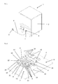
- FIG. 1 shows as an exemplary electrical device 1 a dishwasher with the possibility of device connection to the house electrical installation via the device connection system consisting of Schukostecker 3, device connection line 4, device connection box 5 and device connector 6.
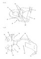
- the FIG. 2 shows a device connector 6 of a device connection system with integrated protective conductor connection for three-phase devices in the installed position on the housing insertion opening 7 of the housing 2 of the exemplary three-phase device in the direction of the outer wall of the inner region of the device 1 ago.
- the device connector 6 is formed trough-like and carries inside the conductor contacts 9, to which the current-carrying, not shown, power supply line is connected by means of plug contacts. These conductor contacts 9 are in operative connection with contacts to which the device internal wiring 16 is connected or connectable.
- the protective conductor contact 17 is arranged, which is operatively connected via the contact lug 11 with the power contact clamping spring 8.
- the trough of the device connector plug 6 has a top on the entire circumference projecting trough edge 20. In this trough edge 20 three side of the device connector plug 6 each two position guides 19 are formed.
- Power.klemmfeder 8 is arranged, which after the plane-parallel placement of the device plug 6 on the housing insertion opening 7 by means of guided through the position guides 19 sliding movement of the device connector 6 with its integrated power contact clamp spring 8 towards the edge of the housing insertion opening. 7 is mechanically and electrically operatively connected to the device housing.
- the power contact clamping spring 8 on the edge region of the housing insertion opening 7 secure the locking lugs 10 integrated on the opposite side of the device connection plug 6 and the trough edge 20 the position of the device connector plug 6 and the power contact terminal spring 8 and thus ensure a permanently secure connection of the Netzschleiter- and the device housing potential.
- FIG. 3 shows the device connection system with integrated protective conductor connection for three-phase devices consisting of separable device connector 6 and device connection box 5 with connected device connection cable 4, power contact clamp spring 8 and latching lugs 10 in mated and thus operatively connected state.
- FIG. 4 is a variant of in FIG. 3 device connection system with integrated protective conductor connection for three-phase devices described in which device connector 6 and device connection box 5 are designed as an inseparable functional unit, which are also referred to as a connection terminal. This is inserted from the outside into the outer wall of the device housing 2.
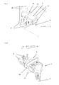
- FIG. 5 shows a device connector 6 of a device connection system with integrated protective conductor connection for connecting AC devices installed in the device housing 2 with connected device internal wiring 16 viewed from the inside of the device.
- the current-carrying connections are configured in a known manner.
- the device connector 6 consists of a parallelepiped, projecting into the interior of the device 1 part at the end of the conductor contacts 9 are mounted. At the other end of the device connector plug 6, a stop collar 21 is arranged.
- the Verrastnasen 10 are on the arranged externally on the device housing 2 stop collar 21, which secure the device connector 6 and arranged on the stop collar 21 towards the device interior power terminal clamp 8 in its installed position in the housing insertion opening 7, and thus a permanently secure operative connection of connected to the power contact clamp spring 8 network protection conductor with the device housing. 2 to ensure.
- housing insertion opening 7 of this When inserting the device connector plug 6 in the higher than the height of the device connector plug 6 formed housing insertion opening 7 of this is moved in the upper part of the housing insertion opening 7 to the abutment of the stop collar 21 on the outer wall of the device housing 2, so that arranged on the underside of the device connector plug 7 Power.klemmfeder 8 is positioned over the outer wall of the device. Thereafter, a “down” press the device connector plug 6, whereby this reaches the engagement position of the power contact clamp spring 8 on the edge of the housing insertion opening 7 of the device housing 2 and the locking latches 10 in the housing insertion opening 7.
- FIG. 6 shows a complete device connection system for AC in functional arrangement consisting of device connector 6 installed in the partially illustrated device housing 2 and the inserted device connection box 5 with the connected device connection cable 4 and the device internal wiring 16 from the insertion of the device connection box 5 in the device connector.
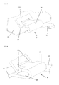
- FIGS. 7, 8 , and 14 show two variants of the formation of the power contact clamping spring 8, which can be used in the aforementioned embodiments.
- FIG. 7 shows the detailed view of an operatively connected to the housing 2 of the electrical device Powerquantklemmfeder 8.
- This power contact clamping spring 8 is integrally formed and U-shaped.
- the end of a leg of the power contact clamping spring 8 is designed by incisions so projecting from the device housing 2 that the front end of an insertion 12 and the opposite end forms a trigger guard claw 13.
- Both legs of the power contact clamping spring 8 comprise the device housing 2 by clamping and form the clamping spring 14.
- On the side of the power contact clamping spring 8, a contact terminal lug 11 is arranged.
- the over-bending of the power contact clamping spring 8 in the direction of the housing secured clamping and spring action of the contact system.
- the trigger guard claw 13 ensures that the power contact clamping spring 8 is self-secured against removal from the device housing. Tolerances or differences in the sheet thicknesses of the device housing 2 are compensated by the clamping spring 14. A relief in the installation of the scraper contact spring ensures the insertion bevel 12th
- FIG. 8 shows separately the in FIG. 7 shown power contact clamping spring 8.
- the particularly large contact surface 15 can be seen, especially in comparison to the conventional in the well-known prior art contacts.
- the contact force of the power contact clamping spring 8 can be controlled over a wide range in conjunction with the trigger guard claws 13.
- FIG. 9 shows a possible embodiment of the device connector plug 6 for device housing 2 with particularly high strength requirements and thus particularly minimalist housing insertion openings 7 in the installed position in the device housing 2 in a perspective view.
- FIG. 11 shows a further possible embodiment of the power contact clamping spring 8 in a perspective view of the device housing of the electrical equipment, in which the sheet metal cut must be performed minimalist for reasons of strength.
- This power contact clamping spring 8 is also formed in one piece and consists of a metal strip, one end of which has a U-shaped recess. This end is bent by two bends so that in cross-section, as it were, a triangle is formed, wherein the original end protrudes perpendicularly from the metal strip as a straight surface and forms the contact surface 15. Furthermore, in the metal strip almost underneath the contact surface 15, an element is unlatched as a trigger guard claw 13.
- the Kunststoffskralle 13 the Kunststoffskralle 13 can be set particularly high and at the same time greater thickness tolerances of the housing plates are compensated.
- FIG. 12 is a further embodiment of the device connector plug 6 in mounting position in front of the device housing 2 shown in a perspective view.
- the basic structure corresponds to the embodiment according to the FIGS. 5 and 6 ,
- the conductor contacts 9 and the protective conductor 17 are incorporated with the contact terminal lug 11 as a connecting element to the clamping spring 14.
- the housing insertion opening 7 is formed round, on the periphery of four in the wall of the device housing 2 outgoing Einzhouaussparungen 22 are arranged.
- retaining elements 23 are arranged with the Einwareaussparungen.
- a power contact clamping spring 8 is arranged instead of the holding element 23, which is also designed correspondingly with the Ein manufacturedaussparitch 22.
- FIG. 13 shows the in FIG. 12 shown device connector 6 in the installed position from the inside of the device out.
- the device plug 6 is shown in its Ein roomdposition in which the holding elements 23 and the power contact clamp spring 8 are latched behind the wall of the device housing 2 between the Ein Industriessparitch 22.
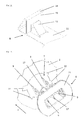
- FIG. 14 shows a special embodiment of the power contact clamping spring 8 without trigger guard claw 13, as shown in FIGS FIGS. 7 and 8 shown.
- the actual contact points between the clamping spring 14 and the wall of the device housing 2 are on the one hand in terms of area and on the other hand formed linear.
- This special embodiment is used in particular when the device housing 2 have special surfaces - eg galvanized, chrome-plated, etc. - and a violation of these could cause the risk of increased corrosion or impairment of the optics.
- FIG. 15 shows an enlarged detail view of a power contact clamp spring 8 with fixing hole 24 without housing.
- the fixing hole 24 may have a thread.
- the fixing hole may be formed as a slot.
- the fixing hole 24 serves as a connecting device.
- FIG. 16 shows a perspective detailed view of an alternative power contact clamping spring 8 with vibration-decoupled connection points with contact elements.
- the individual phases and the protective conductor can be attached by means of solder contact 26.
- solder contact 26 Alternatively, previously described contacting options are realized.
- the relief shaping 25 a vibration decoupling for mechanical vibrations is realized.
Landscapes
- Details Of Connecting Devices For Male And Female Coupling (AREA)
Priority Applications (1)
| Application Number | Priority Date | Filing Date | Title |
|---|---|---|---|
| SI201531886T SI2978075T1 (sl) | 2014-07-22 | 2015-06-16 | Sistem za priključitev naprav z integriranim zaščitnim žičnim priključkom za električne naprave in električna naprava |
Applications Claiming Priority (2)
| Application Number | Priority Date | Filing Date | Title |
|---|---|---|---|
| DE201420103376 DE202014103376U1 (de) | 2014-07-22 | 2014-07-22 | Geräteanschlusssystem mit integriertem Schutzleiteranschluss für elektrische Geräte |
| DE102014110344.0A DE102014110344B4 (de) | 2014-07-22 | 2014-07-22 | Geräteanschlusssystem mit integriertem Schutzleiteranschluss für elektrische Geräte |
Publications (3)
| Publication Number | Publication Date |
|---|---|
| EP2978075A2 true EP2978075A2 (fr) | 2016-01-27 |
| EP2978075A3 EP2978075A3 (fr) | 2016-03-16 |
| EP2978075B1 EP2978075B1 (fr) | 2022-06-29 |
Family
ID=53397987
Family Applications (1)
| Application Number | Title | Priority Date | Filing Date |
|---|---|---|---|
| EP15172422.6A Active EP2978075B1 (fr) | 2014-07-22 | 2015-06-16 | Systeme de raccordement d'appareil doté de raccord de conducteur de protection pour appareils électriques et appareil électrique |
Country Status (6)
| Country | Link |
|---|---|
| EP (1) | EP2978075B1 (fr) |
| ES (1) | ES2926699T3 (fr) |
| HU (1) | HUE059903T2 (fr) |
| PL (1) | PL2978075T3 (fr) |
| PT (1) | PT2978075T (fr) |
| SI (1) | SI2978075T1 (fr) |
Cited By (4)
| Publication number | Priority date | Publication date | Assignee | Title |
|---|---|---|---|---|
| DE202017106710U1 (de) * | 2017-11-07 | 2019-02-08 | Unger Kabel-Konfektionstechnik GmbH | Geräteanschlussterminal für ein Haushaltsgerät sowie Haushaltsgerät |
| EP3584888A1 (fr) * | 2018-06-19 | 2019-12-25 | UNGER Kabel-Konfektionstechnik GmbH | Connecteur d'appareils destiné à être inséré dans une paroi de logement ainsi que système de connecteur appareil et appareil électrique |
| EP3796474A3 (fr) * | 2019-12-10 | 2021-06-02 | UNGER Kabel-Konfektionstechnik GmbH | Dispositif de raccordement permettant de contacter électriquement un appareil électrique |
| IT202000000208A1 (it) * | 2020-01-09 | 2021-07-09 | Te Connectivity Italia S R L | Connettore per montaggio a pannello |
Citations (5)
| Publication number | Priority date | Publication date | Assignee | Title |
|---|---|---|---|---|
| DE102005029384A1 (de) | 2005-06-24 | 2006-12-28 | Electrolux Home Products Corporation N.V. | Elektrisches Verbindungselement |
| DE102005040241A1 (de) | 2005-08-24 | 2007-03-01 | Taller Gmbh | Netzanschlussvorrichtung für Haushaltsgeräte |
| DE102007057335A1 (de) | 2007-11-28 | 2009-06-04 | BSH Bosch und Siemens Hausgeräte GmbH | Haushaltsstandgerät |
| DE102008009142A1 (de) | 2008-02-14 | 2009-08-20 | BSH Bosch und Siemens Hausgeräte GmbH | Elektrische Verbindungseinrichtung |
| DE202013101698U1 (de) | 2013-04-19 | 2013-07-18 | Unger Kabel-Konfektionstechnik GmbH & Co. KG | Schutzleiterkontaktiersystem für Geräteanschlusssysteme elektrischer Geräte |
Family Cites Families (3)
| Publication number | Priority date | Publication date | Assignee | Title |
|---|---|---|---|---|
| US3426818A (en) * | 1967-05-08 | 1969-02-11 | California Ind Prod Inc | Yielding nut retainer |
| US3810069A (en) * | 1972-08-08 | 1974-05-07 | Hubbell Inc Harvey | Grounding clip for electrical fixtures |
| WO2015085995A1 (fr) * | 2013-12-12 | 2015-06-18 | Harting Electric Gmbh & Co. Kg | Cadre de retenue pour un connecteur par enfichage |
-
2015
- 2015-06-16 ES ES15172422T patent/ES2926699T3/es active Active
- 2015-06-16 EP EP15172422.6A patent/EP2978075B1/fr active Active
- 2015-06-16 HU HUE15172422A patent/HUE059903T2/hu unknown
- 2015-06-16 PT PT151724226T patent/PT2978075T/pt unknown
- 2015-06-16 PL PL15172422.6T patent/PL2978075T3/pl unknown
- 2015-06-16 SI SI201531886T patent/SI2978075T1/sl unknown
Patent Citations (5)
| Publication number | Priority date | Publication date | Assignee | Title |
|---|---|---|---|---|
| DE102005029384A1 (de) | 2005-06-24 | 2006-12-28 | Electrolux Home Products Corporation N.V. | Elektrisches Verbindungselement |
| DE102005040241A1 (de) | 2005-08-24 | 2007-03-01 | Taller Gmbh | Netzanschlussvorrichtung für Haushaltsgeräte |
| DE102007057335A1 (de) | 2007-11-28 | 2009-06-04 | BSH Bosch und Siemens Hausgeräte GmbH | Haushaltsstandgerät |
| DE102008009142A1 (de) | 2008-02-14 | 2009-08-20 | BSH Bosch und Siemens Hausgeräte GmbH | Elektrische Verbindungseinrichtung |
| DE202013101698U1 (de) | 2013-04-19 | 2013-07-18 | Unger Kabel-Konfektionstechnik GmbH & Co. KG | Schutzleiterkontaktiersystem für Geräteanschlusssysteme elektrischer Geräte |
Cited By (6)
| Publication number | Priority date | Publication date | Assignee | Title |
|---|---|---|---|---|
| DE202017106710U1 (de) * | 2017-11-07 | 2019-02-08 | Unger Kabel-Konfektionstechnik GmbH | Geräteanschlussterminal für ein Haushaltsgerät sowie Haushaltsgerät |
| EP3480895A1 (fr) | 2017-11-07 | 2019-05-08 | UNGER Kabel-Konfektionstechnik GmbH | Unité de raccordement d'appareils pour un appareil électrique et appareil électrique |
| EP3480895B1 (fr) | 2017-11-07 | 2021-11-10 | UNGER Kabel-Konfektionstechnik GmbH | Unité de raccordement d'appareils pour un appareil électrique et appareil électrique |
| EP3584888A1 (fr) * | 2018-06-19 | 2019-12-25 | UNGER Kabel-Konfektionstechnik GmbH | Connecteur d'appareils destiné à être inséré dans une paroi de logement ainsi que système de connecteur appareil et appareil électrique |
| EP3796474A3 (fr) * | 2019-12-10 | 2021-06-02 | UNGER Kabel-Konfektionstechnik GmbH | Dispositif de raccordement permettant de contacter électriquement un appareil électrique |
| IT202000000208A1 (it) * | 2020-01-09 | 2021-07-09 | Te Connectivity Italia S R L | Connettore per montaggio a pannello |
Also Published As
| Publication number | Publication date |
|---|---|
| ES2926699T3 (es) | 2022-10-27 |
| EP2978075A3 (fr) | 2016-03-16 |
| PL2978075T3 (pl) | 2023-01-09 |
| PT2978075T (pt) | 2022-09-29 |
| SI2978075T1 (sl) | 2022-10-28 |
| EP2978075B1 (fr) | 2022-06-29 |
| HUE059903T2 (hu) | 2023-01-28 |
Similar Documents
| Publication | Publication Date | Title |
|---|---|---|
| DE102008028933B4 (de) | Stromkreisunterbrechungsvorrichtung | |
| EP3342005B1 (fr) | Bloc de jonction électrique | |
| EP2580823A1 (fr) | Connecteur enfichable rapporté | |
| DE202013101698U1 (de) | Schutzleiterkontaktiersystem für Geräteanschlusssysteme elektrischer Geräte | |
| EP3259807B1 (fr) | Bloc de jonction électrique | |
| EP2978075B1 (fr) | Systeme de raccordement d'appareil doté de raccord de conducteur de protection pour appareils électriques et appareil électrique | |
| DE202014103376U1 (de) | Geräteanschlusssystem mit integriertem Schutzleiteranschluss für elektrische Geräte | |
| DE102014110533B4 (de) | Anschlusssystem für elektrische Geräte | |
| DE7837478U1 (de) | AnschluBteU für elektrische Leitungen | |
| EP2429037B1 (fr) | Elément de serrage de cadre pour commutateurs électromécaniques doté d'une pièce de raccordement intégrée | |
| DE202013100297U1 (de) | Geräteanschlusssystem für Küchengeräte | |
| WO2013034443A1 (fr) | Connecteur électrique pourvu d'une protection de contact | |
| DE102012103214B4 (de) | Schaltverteiler und Anordnung aus Schaltverteiler und daran angeschlossener Schalteinheit | |
| EP3504760B1 (fr) | Connecteur multi-contact avec élément intégré à court-circuit | |
| DE102014110344B4 (de) | Geräteanschlusssystem mit integriertem Schutzleiteranschluss für elektrische Geräte | |
| EP3796474B1 (fr) | Dispositif de raccordement permettant de contacter électriquement un appareil électrique | |
| DE102015110171B4 (de) | Elektrische sicherung für ein fahrzeug und damit ausgestatteter elektrischer stromverteiler | |
| DE102012000180A1 (de) | Adapter für elektrische Anschlüsse | |
| EP2859626B1 (fr) | Connecteur électrique avec un lame contact pour se connecter directement avec le panneau de boîtier | |
| EP3439119B1 (fr) | Connecteur d'appareil, système de connexion d'appareil et appareil électrique | |
| DE102010039317B4 (de) | Kontaktelement und System umfassend ein Kontaktelement und ein Gegenkontaktelement | |
| WO2011044998A1 (fr) | Borne à vis à capot et appareil de commutation d'installation | |
| DE202013104941U1 (de) | Elektrische Steckverbinderanordnung und Schirmanbindungselement hierzu | |
| DE102012105901A1 (de) | Zugentlastungseinheit für einen elektrischen Steckverbinder und Gerätegehäuse | |
| DE102007042174A1 (de) | Elektrisches Schaltgerät für ein Kraftfahrzeug |
Legal Events
| Date | Code | Title | Description |
|---|---|---|---|
| PUAI | Public reference made under article 153(3) epc to a published international application that has entered the european phase |
Free format text: ORIGINAL CODE: 0009012 |
|
| AK | Designated contracting states |
Kind code of ref document: A2 Designated state(s): AL AT BE BG CH CY CZ DE DK EE ES FI FR GB GR HR HU IE IS IT LI LT LU LV MC MK MT NL NO PL PT RO RS SE SI SK SM TR |
|
| AX | Request for extension of the european patent |
Extension state: BA ME |
|
| PUAL | Search report despatched |
Free format text: ORIGINAL CODE: 0009013 |
|
| AK | Designated contracting states |
Kind code of ref document: A3 Designated state(s): AL AT BE BG CH CY CZ DE DK EE ES FI FR GB GR HR HU IE IS IT LI LT LU LV MC MK MT NL NO PL PT RO RS SE SI SK SM TR |
|
| AX | Request for extension of the european patent |
Extension state: BA ME |
|
| RIC1 | Information provided on ipc code assigned before grant |
Ipc: H01R 24/78 20110101ALI20160211BHEP Ipc: H01R 13/652 20060101ALI20160211BHEP Ipc: H01R 13/74 20060101ALI20160211BHEP Ipc: H01R 4/64 20060101AFI20160211BHEP Ipc: H02G 15/00 20060101ALI20160211BHEP |
|
| 17P | Request for examination filed |
Effective date: 20160916 |
|
| RBV | Designated contracting states (corrected) |
Designated state(s): AL AT BE BG CH CY CZ DE DK EE ES FI FR GB GR HR HU IE IS IT LI LT LU LV MC MK MT NL NO PL PT RO RS SE SI SK SM TR |
|
| STAA | Information on the status of an ep patent application or granted ep patent |
Free format text: STATUS: EXAMINATION IS IN PROGRESS |
|
| 17Q | First examination report despatched |
Effective date: 20170925 |
|
| RAP1 | Party data changed (applicant data changed or rights of an application transferred) |
Owner name: UNGER KABEL-KONFEKTIONSTECHNIK GMBH |
|
| GRAP | Despatch of communication of intention to grant a patent |
Free format text: ORIGINAL CODE: EPIDOSNIGR1 |
|
| STAA | Information on the status of an ep patent application or granted ep patent |
Free format text: STATUS: GRANT OF PATENT IS INTENDED |
|
| INTG | Intention to grant announced |
Effective date: 20220422 |
|
| GRAS | Grant fee paid |
Free format text: ORIGINAL CODE: EPIDOSNIGR3 |
|
| GRAA | (expected) grant |
Free format text: ORIGINAL CODE: 0009210 |
|
| STAA | Information on the status of an ep patent application or granted ep patent |
Free format text: STATUS: THE PATENT HAS BEEN GRANTED |
|
| AK | Designated contracting states |
Kind code of ref document: B1 Designated state(s): AL AT BE BG CH CY CZ DE DK EE ES FI FR GB GR HR HU IE IS IT LI LT LU LV MC MK MT NL NO PL PT RO RS SE SI SK SM TR |
|
| REG | Reference to a national code |
Ref country code: GB Ref legal event code: FG4D Free format text: NOT ENGLISH |
|
| REG | Reference to a national code |
Ref country code: CH Ref legal event code: EP |
|
| REG | Reference to a national code |
Ref country code: AT Ref legal event code: REF Ref document number: 1501934 Country of ref document: AT Kind code of ref document: T Effective date: 20220715 |
|
| REG | Reference to a national code |
Ref country code: IE Ref legal event code: FG4D Free format text: LANGUAGE OF EP DOCUMENT: GERMAN |
|
| REG | Reference to a national code |
Ref country code: DE Ref legal event code: R096 Ref document number: 502015015924 Country of ref document: DE |
|
| REG | Reference to a national code |
Ref country code: PT Ref legal event code: SC4A Ref document number: 2978075 Country of ref document: PT Date of ref document: 20220929 Kind code of ref document: T Free format text: AVAILABILITY OF NATIONAL TRANSLATION Effective date: 20220923 |
|
| REG | Reference to a national code |
Ref country code: LT Ref legal event code: MG9D |
|
| REG | Reference to a national code |
Ref country code: ES Ref legal event code: FG2A Ref document number: 2926699 Country of ref document: ES Kind code of ref document: T3 Effective date: 20221027 |
|
| PG25 | Lapsed in a contracting state [announced via postgrant information from national office to epo] |
Ref country code: SE Free format text: LAPSE BECAUSE OF FAILURE TO SUBMIT A TRANSLATION OF THE DESCRIPTION OR TO PAY THE FEE WITHIN THE PRESCRIBED TIME-LIMIT Effective date: 20220629 Ref country code: NO Free format text: LAPSE BECAUSE OF FAILURE TO SUBMIT A TRANSLATION OF THE DESCRIPTION OR TO PAY THE FEE WITHIN THE PRESCRIBED TIME-LIMIT Effective date: 20220929 Ref country code: LT Free format text: LAPSE BECAUSE OF FAILURE TO SUBMIT A TRANSLATION OF THE DESCRIPTION OR TO PAY THE FEE WITHIN THE PRESCRIBED TIME-LIMIT Effective date: 20220629 Ref country code: HR Free format text: LAPSE BECAUSE OF FAILURE TO SUBMIT A TRANSLATION OF THE DESCRIPTION OR TO PAY THE FEE WITHIN THE PRESCRIBED TIME-LIMIT Effective date: 20220629 Ref country code: GR Free format text: LAPSE BECAUSE OF FAILURE TO SUBMIT A TRANSLATION OF THE DESCRIPTION OR TO PAY THE FEE WITHIN THE PRESCRIBED TIME-LIMIT Effective date: 20220930 Ref country code: FI Free format text: LAPSE BECAUSE OF FAILURE TO SUBMIT A TRANSLATION OF THE DESCRIPTION OR TO PAY THE FEE WITHIN THE PRESCRIBED TIME-LIMIT Effective date: 20220629 Ref country code: BG Free format text: LAPSE BECAUSE OF FAILURE TO SUBMIT A TRANSLATION OF THE DESCRIPTION OR TO PAY THE FEE WITHIN THE PRESCRIBED TIME-LIMIT Effective date: 20220929 |
|
| REG | Reference to a national code |
Ref country code: NL Ref legal event code: MP Effective date: 20220629 |
|
| REG | Reference to a national code |
Ref country code: SK Ref legal event code: T3 Ref document number: E 40538 Country of ref document: SK |
|
| PG25 | Lapsed in a contracting state [announced via postgrant information from national office to epo] |
Ref country code: RS Free format text: LAPSE BECAUSE OF FAILURE TO SUBMIT A TRANSLATION OF THE DESCRIPTION OR TO PAY THE FEE WITHIN THE PRESCRIBED TIME-LIMIT Effective date: 20220629 Ref country code: LV Free format text: LAPSE BECAUSE OF FAILURE TO SUBMIT A TRANSLATION OF THE DESCRIPTION OR TO PAY THE FEE WITHIN THE PRESCRIBED TIME-LIMIT Effective date: 20220629 |
|
| PG25 | Lapsed in a contracting state [announced via postgrant information from national office to epo] |
Ref country code: NL Free format text: LAPSE BECAUSE OF FAILURE TO SUBMIT A TRANSLATION OF THE DESCRIPTION OR TO PAY THE FEE WITHIN THE PRESCRIBED TIME-LIMIT Effective date: 20220629 |
|
| REG | Reference to a national code |
Ref country code: HU Ref legal event code: AG4A Ref document number: E059903 Country of ref document: HU |
|
| PG25 | Lapsed in a contracting state [announced via postgrant information from national office to epo] |
Ref country code: SM Free format text: LAPSE BECAUSE OF FAILURE TO SUBMIT A TRANSLATION OF THE DESCRIPTION OR TO PAY THE FEE WITHIN THE PRESCRIBED TIME-LIMIT Effective date: 20220629 Ref country code: RO Free format text: LAPSE BECAUSE OF FAILURE TO SUBMIT A TRANSLATION OF THE DESCRIPTION OR TO PAY THE FEE WITHIN THE PRESCRIBED TIME-LIMIT Effective date: 20220629 Ref country code: EE Free format text: LAPSE BECAUSE OF FAILURE TO SUBMIT A TRANSLATION OF THE DESCRIPTION OR TO PAY THE FEE WITHIN THE PRESCRIBED TIME-LIMIT Effective date: 20220629 |
|
| PG25 | Lapsed in a contracting state [announced via postgrant information from national office to epo] |
Ref country code: IS Free format text: LAPSE BECAUSE OF FAILURE TO SUBMIT A TRANSLATION OF THE DESCRIPTION OR TO PAY THE FEE WITHIN THE PRESCRIBED TIME-LIMIT Effective date: 20221029 |
|
| REG | Reference to a national code |
Ref country code: DE Ref legal event code: R097 Ref document number: 502015015924 Country of ref document: DE |
|
| PG25 | Lapsed in a contracting state [announced via postgrant information from national office to epo] |
Ref country code: AL Free format text: LAPSE BECAUSE OF FAILURE TO SUBMIT A TRANSLATION OF THE DESCRIPTION OR TO PAY THE FEE WITHIN THE PRESCRIBED TIME-LIMIT Effective date: 20220629 |
|
| PG25 | Lapsed in a contracting state [announced via postgrant information from national office to epo] |
Ref country code: DK Free format text: LAPSE BECAUSE OF FAILURE TO SUBMIT A TRANSLATION OF THE DESCRIPTION OR TO PAY THE FEE WITHIN THE PRESCRIBED TIME-LIMIT Effective date: 20220629 |
|
| PLBE | No opposition filed within time limit |
Free format text: ORIGINAL CODE: 0009261 |
|
| STAA | Information on the status of an ep patent application or granted ep patent |
Free format text: STATUS: NO OPPOSITION FILED WITHIN TIME LIMIT |
|
| 26N | No opposition filed |
Effective date: 20230330 |
|
| P01 | Opt-out of the competence of the unified patent court (upc) registered |
Effective date: 20230530 |
|
| PG25 | Lapsed in a contracting state [announced via postgrant information from national office to epo] |
Ref country code: MC Free format text: LAPSE BECAUSE OF FAILURE TO SUBMIT A TRANSLATION OF THE DESCRIPTION OR TO PAY THE FEE WITHIN THE PRESCRIBED TIME-LIMIT Effective date: 20220629 |
|
| PG25 | Lapsed in a contracting state [announced via postgrant information from national office to epo] |
Ref country code: MC Free format text: LAPSE BECAUSE OF FAILURE TO SUBMIT A TRANSLATION OF THE DESCRIPTION OR TO PAY THE FEE WITHIN THE PRESCRIBED TIME-LIMIT Effective date: 20220629 |
|
| REG | Reference to a national code |
Ref country code: CH Ref legal event code: PL |
|
| REG | Reference to a national code |
Ref country code: BE Ref legal event code: MM Effective date: 20230630 |
|
| GBPC | Gb: european patent ceased through non-payment of renewal fee |
Effective date: 20230616 |
|
| PG25 | Lapsed in a contracting state [announced via postgrant information from national office to epo] |
Ref country code: LU Free format text: LAPSE BECAUSE OF NON-PAYMENT OF DUE FEES Effective date: 20230616 |
|
| REG | Reference to a national code |
Ref country code: IE Ref legal event code: MM4A |
|
| PG25 | Lapsed in a contracting state [announced via postgrant information from national office to epo] |
Ref country code: LU Free format text: LAPSE BECAUSE OF NON-PAYMENT OF DUE FEES Effective date: 20230616 |
|
| PG25 | Lapsed in a contracting state [announced via postgrant information from national office to epo] |
Ref country code: IE Free format text: LAPSE BECAUSE OF NON-PAYMENT OF DUE FEES Effective date: 20230616 |
|
| PG25 | Lapsed in a contracting state [announced via postgrant information from national office to epo] |
Ref country code: IE Free format text: LAPSE BECAUSE OF NON-PAYMENT OF DUE FEES Effective date: 20230616 Ref country code: GB Free format text: LAPSE BECAUSE OF NON-PAYMENT OF DUE FEES Effective date: 20230616 Ref country code: CH Free format text: LAPSE BECAUSE OF NON-PAYMENT OF DUE FEES Effective date: 20230630 |
|
| PG25 | Lapsed in a contracting state [announced via postgrant information from national office to epo] |
Ref country code: BE Free format text: LAPSE BECAUSE OF NON-PAYMENT OF DUE FEES Effective date: 20230630 |
|
| PG25 | Lapsed in a contracting state [announced via postgrant information from national office to epo] |
Ref country code: BG Free format text: LAPSE BECAUSE OF FAILURE TO SUBMIT A TRANSLATION OF THE DESCRIPTION OR TO PAY THE FEE WITHIN THE PRESCRIBED TIME-LIMIT Effective date: 20220629 |
|
| PG25 | Lapsed in a contracting state [announced via postgrant information from national office to epo] |
Ref country code: BG Free format text: LAPSE BECAUSE OF FAILURE TO SUBMIT A TRANSLATION OF THE DESCRIPTION OR TO PAY THE FEE WITHIN THE PRESCRIBED TIME-LIMIT Effective date: 20220629 |
|
| PGFP | Annual fee paid to national office [announced via postgrant information from national office to epo] |
Ref country code: PL Payment date: 20250605 Year of fee payment: 11 Ref country code: DE Payment date: 20250307 Year of fee payment: 11 |
|
| PGFP | Annual fee paid to national office [announced via postgrant information from national office to epo] |
Ref country code: PT Payment date: 20250603 Year of fee payment: 11 |
|
| PGFP | Annual fee paid to national office [announced via postgrant information from national office to epo] |
Ref country code: HU Payment date: 20250613 Year of fee payment: 11 Ref country code: FR Payment date: 20250627 Year of fee payment: 11 |
|
| PGFP | Annual fee paid to national office [announced via postgrant information from national office to epo] |
Ref country code: AT Payment date: 20250616 Year of fee payment: 11 |
|
| PG25 | Lapsed in a contracting state [announced via postgrant information from national office to epo] |
Ref country code: CY Free format text: LAPSE BECAUSE OF FAILURE TO SUBMIT A TRANSLATION OF THE DESCRIPTION OR TO PAY THE FEE WITHIN THE PRESCRIBED TIME-LIMIT; INVALID AB INITIO Effective date: 20150616 |
|
| PGFP | Annual fee paid to national office [announced via postgrant information from national office to epo] |
Ref country code: TR Payment date: 20250613 Year of fee payment: 11 Ref country code: SK Payment date: 20250605 Year of fee payment: 11 |
|
| PGFP | Annual fee paid to national office [announced via postgrant information from national office to epo] |
Ref country code: CZ Payment date: 20250605 Year of fee payment: 11 |
|
| PGFP | Annual fee paid to national office [announced via postgrant information from national office to epo] |
Ref country code: SI Payment date: 20250604 Year of fee payment: 11 |
|
| PGFP | Annual fee paid to national office [announced via postgrant information from national office to epo] |
Ref country code: ES Payment date: 20250718 Year of fee payment: 11 |
|
| PGFP | Annual fee paid to national office [announced via postgrant information from national office to epo] |
Ref country code: IT Payment date: 20250630 Year of fee payment: 11 |