EP2230448A1 - Cascade de miroirs à DEL - Google Patents
Cascade de miroirs à DEL Download PDFInfo
- Publication number
- EP2230448A1 EP2230448A1 EP10002663A EP10002663A EP2230448A1 EP 2230448 A1 EP2230448 A1 EP 2230448A1 EP 10002663 A EP10002663 A EP 10002663A EP 10002663 A EP10002663 A EP 10002663A EP 2230448 A1 EP2230448 A1 EP 2230448A1
- Authority
- EP
- European Patent Office
- Prior art keywords
- reflector
- light sources
- luminaire according
- recesses
- surface structure
- Prior art date
- Legal status (The legal status is an assumption and is not a legal conclusion. Google has not performed a legal analysis and makes no representation as to the accuracy of the status listed.)
- Withdrawn
Links
Images



Classifications
-
- F—MECHANICAL ENGINEERING; LIGHTING; HEATING; WEAPONS; BLASTING
- F21—LIGHTING
- F21V—FUNCTIONAL FEATURES OR DETAILS OF LIGHTING DEVICES OR SYSTEMS THEREOF; STRUCTURAL COMBINATIONS OF LIGHTING DEVICES WITH OTHER ARTICLES, NOT OTHERWISE PROVIDED FOR
- F21V11/00—Screens not covered by groups F21V1/00, F21V3/00, F21V7/00 or F21V9/00
- F21V11/08—Screens not covered by groups F21V1/00, F21V3/00, F21V7/00 or F21V9/00 using diaphragms containing one or more apertures
- F21V11/14—Screens not covered by groups F21V1/00, F21V3/00, F21V7/00 or F21V9/00 using diaphragms containing one or more apertures with many small apertures
-
- F—MECHANICAL ENGINEERING; LIGHTING; HEATING; WEAPONS; BLASTING
- F21—LIGHTING
- F21V—FUNCTIONAL FEATURES OR DETAILS OF LIGHTING DEVICES OR SYSTEMS THEREOF; STRUCTURAL COMBINATIONS OF LIGHTING DEVICES WITH OTHER ARTICLES, NOT OTHERWISE PROVIDED FOR
- F21V7/00—Reflectors for light sources
- F21V7/0025—Combination of two or more reflectors for a single light source
-
- F—MECHANICAL ENGINEERING; LIGHTING; HEATING; WEAPONS; BLASTING
- F21—LIGHTING
- F21V—FUNCTIONAL FEATURES OR DETAILS OF LIGHTING DEVICES OR SYSTEMS THEREOF; STRUCTURAL COMBINATIONS OF LIGHTING DEVICES WITH OTHER ARTICLES, NOT OTHERWISE PROVIDED FOR
- F21V7/00—Reflectors for light sources
- F21V7/0083—Array of reflectors for a cluster of light sources, e.g. arrangement of multiple light sources in one plane
-
- F—MECHANICAL ENGINEERING; LIGHTING; HEATING; WEAPONS; BLASTING
- F21—LIGHTING
- F21V—FUNCTIONAL FEATURES OR DETAILS OF LIGHTING DEVICES OR SYSTEMS THEREOF; STRUCTURAL COMBINATIONS OF LIGHTING DEVICES WITH OTHER ARTICLES, NOT OTHERWISE PROVIDED FOR
- F21V7/00—Reflectors for light sources
- F21V7/22—Reflectors for light sources characterised by materials, surface treatments or coatings, e.g. dichroic reflectors
- F21V7/24—Reflectors for light sources characterised by materials, surface treatments or coatings, e.g. dichroic reflectors characterised by the material
-
- F—MECHANICAL ENGINEERING; LIGHTING; HEATING; WEAPONS; BLASTING
- F21—LIGHTING
- F21V—FUNCTIONAL FEATURES OR DETAILS OF LIGHTING DEVICES OR SYSTEMS THEREOF; STRUCTURAL COMBINATIONS OF LIGHTING DEVICES WITH OTHER ARTICLES, NOT OTHERWISE PROVIDED FOR
- F21V7/00—Reflectors for light sources
- F21V7/22—Reflectors for light sources characterised by materials, surface treatments or coatings, e.g. dichroic reflectors
- F21V7/28—Reflectors for light sources characterised by materials, surface treatments or coatings, e.g. dichroic reflectors characterised by coatings
-
- F—MECHANICAL ENGINEERING; LIGHTING; HEATING; WEAPONS; BLASTING
- F21—LIGHTING
- F21V—FUNCTIONAL FEATURES OR DETAILS OF LIGHTING DEVICES OR SYSTEMS THEREOF; STRUCTURAL COMBINATIONS OF LIGHTING DEVICES WITH OTHER ARTICLES, NOT OTHERWISE PROVIDED FOR
- F21V13/00—Producing particular characteristics or distribution of the light emitted by means of a combination of elements specified in two or more of main groups F21V1/00 - F21V11/00
- F21V13/02—Combinations of only two kinds of elements
- F21V13/10—Combinations of only two kinds of elements the elements being reflectors and screens
-
- F—MECHANICAL ENGINEERING; LIGHTING; HEATING; WEAPONS; BLASTING
- F21—LIGHTING
- F21Y—INDEXING SCHEME ASSOCIATED WITH SUBCLASSES F21K, F21L, F21S and F21V, RELATING TO THE FORM OR THE KIND OF THE LIGHT SOURCES OR OF THE COLOUR OF THE LIGHT EMITTED
- F21Y2105/00—Planar light sources
- F21Y2105/10—Planar light sources comprising a two-dimensional [2D] array of point-like light-generating elements
-
- F—MECHANICAL ENGINEERING; LIGHTING; HEATING; WEAPONS; BLASTING
- F21—LIGHTING
- F21Y—INDEXING SCHEME ASSOCIATED WITH SUBCLASSES F21K, F21L, F21S and F21V, RELATING TO THE FORM OR THE KIND OF THE LIGHT SOURCES OR OF THE COLOUR OF THE LIGHT EMITTED
- F21Y2115/00—Light-generating elements of semiconductor light sources
- F21Y2115/10—Light-emitting diodes [LED]
Definitions
- the present invention relates to a surface-trained lamp with a plurality of point-shaped light sources, which are distributed in a planar arrangement associated with a reflector.
- the light sources are arranged visibly in the ceiling, on the one hand the aforementioned glare effect occurs. On the other hand, even in the off state, the surface effect of the ceiling or its designability affected by the visible light sources.
- the font DE 101 24 539 describes an LED light, which is not designed as a stationary light for the illumination of building spaces and squares, but as a motor vehicle tail light.
- the LEDs are arranged in recesses of a faceted reflector, wherein a pinhole is placed under the cover glass of the taillight in front of the bulb reflector assembly to produce the fashionable in motor vehicles phenomenon of a light source grid.
- the aforementioned pinhole is not reflective, so that it comes to relatively high radiation losses.
- the size of the perforation is intended to leave the bulbs behind the pinhole visible, which is not acceptable for stationary building lights due to the resulting glare.
- the present invention has for its object to provide an improved luminaire of the type mentioned above, which avoids the disadvantages of the prior art and the latter develops in an advantageous manner.
- a wide distribution of light with a balanced ratio of vertical to horizontal illuminance with simultaneous depth effect of the visual appearance of the lamp should be achieved with a high degree of glare, without sacrificing good efficiency of the lamp.
- a second reflector is provided at a distance from said first reflector, which reflector is designed to be reflective on its surface facing the first reflector and is provided with a fine light emission perforation.
- the hole structure here is advantageously designed so that a transparency to the first reflector is created and the visual image, which cause the two reflectors in addition, creates a so-called dematerialized appearance.
- the lamp gets a depth effect, since the light seems to come from different levels.
- the light sources are in the off state behind the second, perforated reflector more or less invisible, so that the lamp is architecturally versatile and not disturb the ceiling or mural when switched off.
- the underside or the space-facing side of the second reflector can be designed as desired, for example, coated in color, printed with a pattern or provided with any other desired surface structure or design.
- the Lichtaustrittslochung in the second reflector is hereby advantageously so finely formed that the image of the underlying point-shaped light sources and / or the light image generated by the first reflector is smashed so to speak.
- This smashing of the image of the light sources in a variety of points of light causes much less glare or completely eliminates glare.
- the hole spacing of the perforation of the second reflector is advantageously much smaller than the distance of the light sources.
- the number of fine holes in the second reflector may be at least ten times as large, preferably more than one hundred times as large and in particular be more than a thousand times as large as the number of punctiform light sources.
- the hole spacing may be less than 1/3, preferably also less than 1/10 and in particular less than 1/30 of the distance of the point-shaped light sources from each other.
- the holes of the Lichtaustrittslochung this advantageously have a hole diameter that is smaller than the diameter of the light sources, so that even when looking directly into the light not the entire light source can be seen as a single point.
- the hole diameter of the reflector holes can be chosen differently, wherein advantageously the hole diameter is less than 1 ⁇ 2 times the diameter of the light source.
- LEDs are used as punctiform light sources
- a hole diameter of less than 2 mm can be provided in an advantageous embodiment of the invention, wherein advantageously the hole diameter is less than 1 mm.
- the diameter of the punctiform light sources may be between 2 and 5 mm in the case of using LEDs.
- not only LEDs can be used, but also other preferably punctiform light sources are used, for example halogen incandescent lamps.
- the first reflector whose reflective surface facing the illuminated space, advantageously not flat, but with an embossing of the light reflective surface formed or an optically active surface structure provided.
- the light is reflected not only straight or the same direction on the second reflector or thrown through the perforation through, but there are differently directed reflections, which creates a variety of mirror images in conjunction with the transparency of the perforated second reflector.
- the aforementioned surface structure of the reflective surface of the first reflector can in principle be designed differently.
- a faceted surface structure is provided which does not give rise to a milky-uniform mirror image, but rather gives rise to a multiplicity of discrete mirror images whose arrangement varies depending on the viewing angle of the luminaire.
- the facet-shaped embossing of the reflective surface of the first reflector makes the surface-shaped light in the manner of a diamond always sparkle differently when the viewer moves through the illuminated space.
- the surface structure of the first reflector may comprise a plurality of trough-shaped recesses, which are preferably distributed in a corresponding arrangement with the planar, distributed arrangement of the light sources.
- the recesses mentioned are advantageously formed facet-shaped, in particular pyramidal depressions may be provided.
- the pyramids may have triangular, square, pentagonal or hexagonal bases, with a good compromise between a simple production on the one hand and a sufficiently high mirror multiplication by To achieve a pyramid structure of pyramids with a square plan.
- the depressions of the surface structure in this case advantageously have a relatively large opening angle of preferably at least 2 x 45 ° in order to ensure a broad illumination.
- the depressions can have an opening angle in the range of 2 ⁇ 50 ° to 2 ⁇ 70 ° and preferably about 2 ⁇ 60 °.
- the depth of said depressions of the surface structure is advantageously smaller than the diagonal over the upper edge of a trough-shaped depression or over the opening cross-section of the depression.
- the pyramid depth or height may be less than 50% of the diagonal across the pyramid base.
- the trough-shaped depressions of the faceted surface structure are advantageously subdivided into a plurality of distinguishable and delimited surface segments, wherein advantageously a subdivision into planar surface segments is provided, as is the case, for example, with diamond grinding.
- the point-shaped light sources are advantageously arranged in the trough-shaped depressions of the surface structure, wherein the light sources are advantageously centered and / or positioned at the bottom of the respective recess.
- the point-shaped light sources may be arranged on a printed circuit board which extends behind the first reflector.
- Said first reflector advantageously has a multiplicity of through-openings, through which the point-shaped light sources are inserted from a rear side of the reflector into the trough-shaped recesses.
- the second reflector which has said light exit holes, advantageously has a different surface shape from the first reflector.
- said second reflector is planar and / or free of a surface structure.
- said second reflector may also be uneven.
- the second reflector when an asymmetric light emission is desired, it may be advantageous if the second reflector is provided with an asymmetric surface structure and / or an asymmetric embossing.
- said second reflector may have an asymmetrical fold in which the holes of the light exit perforation are oriented all and / or in predominate numbers to one side, in particular in legs of the fold are directed, which are directed to the same side.
- the first reflector is also provided with an asymmetric embossing or surface structure, whereby advantageously the main direction of the surface structure of the first reflector is tilted towards the same side as the main axis of the surface structure of the second reflector.
- asymmetric radiation can be achieved with high efficiency.
- the major axes of the pyramids are tilted at an acute angle of less than 90 ° to the plane of said first reflector.
- the second reflector is provided with said oblique fold, the major axes of the fold, which divide a respective fold into two equal opening angles, are tilted towards the same side at an equally acute angle of less than 90 °.
- the two reflectors are advantageously arranged in mutually parallel planes.
- a movable, in particular displaceable mounting of at least one of the reflectors can advantageously be provided.
- the distance variable mounting or mounting of the two reflectors allows a simple change of the depth effect and adaptation of the lamp to different installation situations.
- the second reflector is flat or it may be formed in the form of a flat plate having said perforation.
- the first reflector is advantageously shaped in relief and provided with the aforementioned trough-like depressions, but in this case may have a flat envelope surface, i. the aforementioned recesses lie with their opening and / or bottom cross-sections in each case in a common plane.
- the light can be designed overall in the form of a flat panel, so that it can be fitted to the usual flat ceiling and wall contours in an advantageous manner as a wall and / or ceiling light.
- the light sources can also be arranged in a common plane.
- the lamp or the first and second reflectors may also have a preferably regular, continuous and continuous curvature, for example, to adapt to a barrel-shaped ceiling have a cylindrical, trough-shaped or paraboloidal curvature, which is also advantageously provided here to provide the first and second reflectors with corresponding arches and / or to arrange them in a substantially constant distance from one another over the surfaces.
- the first reflector, the second reflector and the light sources are arranged in mutually parallel planes.
- the reflective surfaces of the two reflectors are each formed highly reflective, which in the invention, a reflectance of at least 90%, preferably at least 95% and in particular 97% or more may be provided.
- the second reflector has a hole content of preferably 5% to 25%, i. 95% to 75% of the area of the reflector is formed by reflective material, while the hole area accounts for about 5% to 25% of the total area of the reflector.
- said hole proportion is 10% to 15%, whereby a good compromise between transparency and depth effect on the one hand and glare on the other hand is achieved.
- the mirror cascade shown in the figures forms a lighting system that is flat and module-small area or can be applied to extended areas.
- the room can be zoned or evenly illuminated.
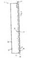
- the lamp 1 comprises a substantially cuboid, flat housing 2, which may be formed, for example, as a sheet metal or plastic box and receives in its interior the functional components of the lamp.
- a printed circuit board 4 is arranged, on which in a regular grid a plurality of point-shaped light sources 3 are arranged, which are formed in the illustrated embodiment as LEDs.
- a first reflector 5 which has an optically active surface structure 13 in the form of an embossment, which consists in the illustrated embodiment of a plurality of pyramidal depressions 9, which are arranged in a regular grid, which the grid of light sources 3 corresponds.
- an optically active surface structure 13 in the form of an embossment, which consists in the illustrated embodiment of a plurality of pyramidal depressions 9, which are arranged in a regular grid, which the grid of light sources 3 corresponds.
- the surface of said first reflector 5 provided with said pyramidal or faceted surface structure 13 is highly reflective designed to minimize losses.
- the reflector 5 may be formed of an aluminum sheet with a highly reflective coating of Miro-Silver with a reflectance of 97%.
- the pyramidal depressions 9 have a square plan, so that the depressions have the contour of a four-sided, uniform pyramid.
- the depth t of the recesses 9 is significantly smaller than the dimension of the clear width w at the top of the pyramidal recesses 9.
- the opening angle of the pyramidal recesses 9 is twice 60 °.
- the base surface of the pyramidal recesses 9 may vary in size. In the illustrated embodiment, it is on the order of 5 x 5 cm and 15 x 15 cm, wherein advantageously all depressions 9 have substantially the same geometry.
- the arrangement of the recesses 9 is made in a uniform grid.
- the surface structure 13 in the form of the depressions 9 extends essentially over the entire surface of the reflector 5 or substantially over the entire base area of the luminaire 1.
- first reflector 5 sits a second reflector 6, which is spaced from the first reflector 5 and is arranged in a plane parallel to the plane of the first reflector 5.
- the first reflector 5 is in the illustrated embodiment according to Fig. 2 formed substantially planar and formed on its side facing the first reflector 5 side reflective. Also for the second reflector 6, a highly reflective surface is provided in order to achieve a high efficiency.
- the second reflector 6 can also consist, for example, of an aluminum sheet which is provided with a highly reflective surface coating made of Miro-Silver with a reflectance of 97%.
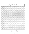
- Said second reflector 6 is in this case provided with a fine Lichtausbergslochung 7, which consists in the illustrated embodiment of a plurality of holes 8, which are arranged in a uniform grid, as Fig. 1 suggests.
- the said holes 8 are in this case of their diameter significantly smaller than the base surface of the recesses 9 of the surface structure 13 of the first reflector 5, and in particular also significantly smaller than the diameter of the punctiform light sources 3.
- the diameter d of the holes. 8 the perforation 7 is less than 1 mm and is about 0.8 to 0.9 mm.
- the hole spacing a of the light exit holes 7 is also significantly smaller than the distance b of the point-shaped light sources 3, ie the grid of the light exit holes 7 is significantly finer than the grid of the light sources. 3
- the spacing of the two reflectors 5 and 6 can be fundamentally different, with the depth effect of the luminaire can be changed by changing the distance between the two reflectors 5 and 6.
- the side of the second reflector 6 facing away from the first reflector 5, i. the light exit side of the luminaire can be designed variably and does not have to be reflective.
- the light exit side of the second reflector 6 may be colored coated to architecturally adapt the light to the desired interior design.
- the second reflector 6 advantageously sits a transparent cover 15 to prevent dust from entering through the Lichtaustrittslochung 7 in the interior of the lamp.
- the cover 15 in this case advantageously includes flush with the housing 2.
- Fig. 4 clarifies the by the light after the FIGS. 1 to 3 achievable beam path.
- the radiated from the point-shaped light sources 3 rays first meet the second reflector 6, wherein a part of the rays, which hit the holes 8 of the Lichtaustrittslochung 7, pass through the reflector 6, while the rest of the rays from the reflective surface of the second Reflectors 6 are thrown back.
- Fig. 5 shows an alternative embodiment of the lamp 1, in which the first reflector 5 and the second reflector 6 are provided with an asymmetric or to a side inclined surface structure, so that an asymmetric radiation image is obtained, which is perpendicular to the plane of the lamp 1 is inclined, cf. Fig. 5 ,
- the second reflector 6 is not flat, but also provided with an embossing or formed in relief.
- the second reflector 6 in the illustrated embodiment Fig. 5 provided with a fold 10, which gives rise to a channel-shaped or corrugated sheet contouring of the second reflector 6, wherein the fold 10, however, so to speak here faceted, that is formed of flat surface portions with a Kantung between adjacent surface portions.
- Fig. 5 shows, in this case, the fold 10 is formed asymmetrically or inclined.
- a main axis 11 on the fold 10 is inclined at an acute angle to the reflector plane, wherein as the main axis 11, the entire opening angle centered halving straight line is meant, see.
- Fig. 5 the entire opening angle centered halving straight line is meant, see.
- the first reflector 5 is similar to the previously described embodiment with a surface structure 13 comprising pyramidal recesses 9, but here the recesses 9 are contoured in the form of slanted pyramids, so that main axes 12, which divide the opening angle of the recesses 9 centrally, also acute angle to Reflective plane are inclined, see. Fig. 5 ,
- Fig. 5 shows, the longer portions of the fold 10 are aligned parallel to the flatter flanks of the recesses 9, while the shorter portions of the fold 10 are perpendicular thereto. This results in the in Fig. 5 illustrated beam path.
Landscapes
- Engineering & Computer Science (AREA)
- General Engineering & Computer Science (AREA)
- Non-Portable Lighting Devices Or Systems Thereof (AREA)
Applications Claiming Priority (1)
| Application Number | Priority Date | Filing Date | Title |
|---|---|---|---|
| DE102009013811A DE102009013811A1 (de) | 2009-03-18 | 2009-03-18 | LED-Spiegelkaskade |
Publications (1)
| Publication Number | Publication Date |
|---|---|
| EP2230448A1 true EP2230448A1 (fr) | 2010-09-22 |
Family
ID=42199747
Family Applications (1)
| Application Number | Title | Priority Date | Filing Date |
|---|---|---|---|
| EP10002663A Withdrawn EP2230448A1 (fr) | 2009-03-18 | 2010-03-12 | Cascade de miroirs à DEL |
Country Status (2)
| Country | Link |
|---|---|
| EP (1) | EP2230448A1 (fr) |
| DE (1) | DE102009013811A1 (fr) |
Cited By (2)
| Publication number | Priority date | Publication date | Assignee | Title |
|---|---|---|---|---|
| CN103270365A (zh) * | 2010-12-21 | 2013-08-28 | 皇家飞利浦电子股份有限公司 | 照明系统和制造方法 |
| CN114466992A (zh) * | 2019-11-15 | 2022-05-10 | 株式会社小糸制作所 | 灯具单元 |
Citations (6)
| Publication number | Priority date | Publication date | Assignee | Title |
|---|---|---|---|---|
| DE20116022U1 (de) * | 2001-04-09 | 2002-01-24 | Bartenbach, Christian, Aldrans, Tirol | Leuchtenfeld zur Beleuchtung von Räumen mit einer Vielzahl von LEDs |
| DE10124539A1 (de) | 2001-05-19 | 2002-11-21 | Reitter & Schefenacker Gmbh | Heckleuchte für Fahrzeuge, insbesondere für Kraftfahrzeuge |
| WO2007096559A1 (fr) * | 2006-02-22 | 2007-08-30 | Peugeot Citroën Automobiles | Bloc optique a fonctions d'eclairement couplees |
| EP1843081A2 (fr) * | 2006-04-03 | 2007-10-10 | Nimbus Design GmbH | Eclairage, en particulier éclairage d'intérieur |
| US20080239751A1 (en) * | 2007-03-27 | 2008-10-02 | Hon Hai Precision Industry Co., Ltd. | Led lamp assembly |
| US20080304250A1 (en) | 2007-06-06 | 2008-12-11 | Philips Lumileds Lighting Company, Llc | Thin Luminaire for General Lighting Applications |
Family Cites Families (3)
| Publication number | Priority date | Publication date | Assignee | Title |
|---|---|---|---|---|
| DE10303969B4 (de) * | 2003-01-31 | 2008-11-27 | Osram Opto Semiconductors Gmbh | Leuchtdiodenanordnung mit einem Leuchtdiodenträger und einer Mehrzahl von Leuchtdioden |
| EP1623153A1 (fr) * | 2003-05-15 | 2006-02-08 | Lucea AG | Source lumineuse |
| DE202004001742U1 (de) * | 2003-11-10 | 2004-04-08 | indoor bau RÖHRICHT gmbh | Präsentationsvitrine |
-
2009
- 2009-03-18 DE DE102009013811A patent/DE102009013811A1/de not_active Withdrawn
-
2010
- 2010-03-12 EP EP10002663A patent/EP2230448A1/fr not_active Withdrawn
Patent Citations (6)
| Publication number | Priority date | Publication date | Assignee | Title |
|---|---|---|---|---|
| DE20116022U1 (de) * | 2001-04-09 | 2002-01-24 | Bartenbach, Christian, Aldrans, Tirol | Leuchtenfeld zur Beleuchtung von Räumen mit einer Vielzahl von LEDs |
| DE10124539A1 (de) | 2001-05-19 | 2002-11-21 | Reitter & Schefenacker Gmbh | Heckleuchte für Fahrzeuge, insbesondere für Kraftfahrzeuge |
| WO2007096559A1 (fr) * | 2006-02-22 | 2007-08-30 | Peugeot Citroën Automobiles | Bloc optique a fonctions d'eclairement couplees |
| EP1843081A2 (fr) * | 2006-04-03 | 2007-10-10 | Nimbus Design GmbH | Eclairage, en particulier éclairage d'intérieur |
| US20080239751A1 (en) * | 2007-03-27 | 2008-10-02 | Hon Hai Precision Industry Co., Ltd. | Led lamp assembly |
| US20080304250A1 (en) | 2007-06-06 | 2008-12-11 | Philips Lumileds Lighting Company, Llc | Thin Luminaire for General Lighting Applications |
Cited By (3)
| Publication number | Priority date | Publication date | Assignee | Title |
|---|---|---|---|---|
| CN103270365A (zh) * | 2010-12-21 | 2013-08-28 | 皇家飞利浦电子股份有限公司 | 照明系统和制造方法 |
| CN114466992A (zh) * | 2019-11-15 | 2022-05-10 | 株式会社小糸制作所 | 灯具单元 |
| CN114466992B (zh) * | 2019-11-15 | 2024-06-07 | 株式会社小糸制作所 | 灯具单元 |
Also Published As
| Publication number | Publication date |
|---|---|
| DE102009013811A1 (de) | 2010-09-23 |
Similar Documents
| Publication | Publication Date | Title |
|---|---|---|
| EP1353117B1 (fr) | Luminaire | |
| EP1154200B1 (fr) | Distributeur de lumière pour un système d'éclairage, système d'éclairage et utilisation d' un système d'éclairage | |
| EP1979668B1 (fr) | Lampe comprenant un logement sous forme de boitier et element de sortie d'eclairage | |
| DE202007013205U1 (de) | Leuchte | |
| EP1697683A1 (fr) | Lampe encastree | |
| EP3199869B1 (fr) | Dispositif d'éclairage | |
| DE102009013811A1 (de) | LED-Spiegelkaskade | |
| EP2679888B1 (fr) | Dispositif d'éclairage | |
| EP4034807A1 (fr) | Luminaire ayant une région pour émettre de la lumière sur une surface | |
| EP3408587B1 (fr) | Système optique destiné à influer sur l'émission de lumière d'une source de lumière | |
| EP2679889A2 (fr) | Dispositif dýéclairage | |
| EP0813026A2 (fr) | Dispositif d'éclairage | |
| DE10018499B4 (de) | Flachleuchte mit gleichmäßiger Abstrahlcharakteristik | |
| DE102006019202A1 (de) | Flachleuchte zur Ausstrahlung von Licht in einer bauformabhängigen Richtung mit bauformabhängigem Helligkeitsprofil | |
| EP1584861B1 (fr) | Lampe de plafond ergonomique | |
| EP4168711B1 (fr) | Ensemble d'émission de lumière, et luminaire | |
| DE102014104339B4 (de) | Zentrales Aufhellungselement für LED-Leuchten | |
| EP1900998B1 (fr) | Réflecteur doté d'une structure émettant de la lumière | |
| EP2019255A2 (fr) | Lampe pour éclairer une surface dans un bâtiment | |
| EP1039217A1 (fr) | Dispositif d'un corps d'éclairage | |
| EP3889499A1 (fr) | Luminaire pourvu de source lumineuse et système optique associé | |
| DE102015205979B4 (de) | Optische Signalisierungsvorrichtung für einen Fahrzeugscheinwerfer | |
| EP2765353B1 (fr) | Lampe avec une un arrangement de Disque conducteur de lumière | |
| DE20122591U1 (de) | Leuchte | |
| DE20023536U1 (de) | Flachleuchte mit gleichmäßiger Abstrahlcharakteristik |
Legal Events
| Date | Code | Title | Description |
|---|---|---|---|
| PUAI | Public reference made under article 153(3) epc to a published international application that has entered the european phase |
Free format text: ORIGINAL CODE: 0009012 |
|
| AK | Designated contracting states |
Kind code of ref document: A1 Designated state(s): AT BE BG CH CY CZ DE DK EE ES FI FR GB GR HR HU IE IS IT LI LT LU LV MC MK MT NL NO PL PT RO SE SI SK SM TR |
|
| AX | Request for extension of the european patent |
Extension state: AL BA ME RS |
|
| 17P | Request for examination filed |
Effective date: 20110318 |
|
| RAP1 | Party data changed (applicant data changed or rights of an application transferred) |
Owner name: BARTENBACH HOLDING GMBH |
|
| RIN1 | Information on inventor provided before grant (corrected) |
Inventor name: BARTENBACH HOLDING GMBH |
|
| RIN1 | Information on inventor provided before grant (corrected) |
Inventor name: BARTENBACH, CHRISTIAN |
|
| STAA | Information on the status of an ep patent application or granted ep patent |
Free format text: STATUS: THE APPLICATION IS DEEMED TO BE WITHDRAWN |
|
| 18D | Application deemed to be withdrawn |
Effective date: 20121002 |