EP2679889A2 - Dispositif dýéclairage - Google Patents
Dispositif dýéclairage Download PDFInfo
- Publication number
- EP2679889A2 EP2679889A2 EP13003257.6A EP13003257A EP2679889A2 EP 2679889 A2 EP2679889 A2 EP 2679889A2 EP 13003257 A EP13003257 A EP 13003257A EP 2679889 A2 EP2679889 A2 EP 2679889A2
- Authority
- EP
- European Patent Office
- Prior art keywords
- light
- reflector
- surface structure
- scattering
- reflector surface
- Prior art date
- Legal status (The legal status is an assumption and is not a legal conclusion. Google has not performed a legal analysis and makes no representation as to the accuracy of the status listed.)
- Granted
Links
- 238000005286 illumination Methods 0.000 title claims description 6
- 239000004753 textile Substances 0.000 claims abstract description 59
- 238000000149 argon plasma sintering Methods 0.000 claims abstract description 38
- 239000004744 fabric Substances 0.000 claims abstract description 7
- 239000000463 material Substances 0.000 claims description 25
- 230000005855 radiation Effects 0.000 claims description 20
- 229910052751 metal Inorganic materials 0.000 claims description 7
- 239000002184 metal Substances 0.000 claims description 7
- 238000004049 embossing Methods 0.000 claims description 5
- 230000001788 irregular Effects 0.000 claims description 4
- 229910000838 Al alloy Inorganic materials 0.000 claims 1
- 230000003247 decreasing effect Effects 0.000 claims 1
- 244000144992 flock Species 0.000 claims 1
- 230000000694 effects Effects 0.000 description 16
- 230000004313 glare Effects 0.000 description 9
- 238000000354 decomposition reaction Methods 0.000 description 3
- 239000000835 fiber Substances 0.000 description 3
- 239000007787 solid Substances 0.000 description 3
- 229910052782 aluminium Inorganic materials 0.000 description 2
- XAGFODPZIPBFFR-UHFFFAOYSA-N aluminium Chemical compound [Al] XAGFODPZIPBFFR-UHFFFAOYSA-N 0.000 description 2
- 230000001419 dependent effect Effects 0.000 description 2
- 238000009826 distribution Methods 0.000 description 2
- 230000006870 function Effects 0.000 description 2
- 239000000203 mixture Substances 0.000 description 2
- 230000003287 optical effect Effects 0.000 description 2
- 239000004033 plastic Substances 0.000 description 2
- BASFCYQUMIYNBI-UHFFFAOYSA-N platinum Chemical compound [Pt] BASFCYQUMIYNBI-UHFFFAOYSA-N 0.000 description 2
- 239000011148 porous material Substances 0.000 description 2
- 239000002759 woven fabric Substances 0.000 description 2
- 230000006978 adaptation Effects 0.000 description 1
- 238000005282 brightening Methods 0.000 description 1
- 239000012876 carrier material Substances 0.000 description 1
- 238000005253 cladding Methods 0.000 description 1
- 239000011248 coating agent Substances 0.000 description 1
- 238000000576 coating method Methods 0.000 description 1
- 230000006735 deficit Effects 0.000 description 1
- 239000006185 dispersion Substances 0.000 description 1
- 238000005516 engineering process Methods 0.000 description 1
- 239000006260 foam Substances 0.000 description 1
- 239000011888 foil Substances 0.000 description 1
- 238000007373 indentation Methods 0.000 description 1
- 238000009434 installation Methods 0.000 description 1
- 239000010410 layer Substances 0.000 description 1
- 239000002346 layers by function Substances 0.000 description 1
- 238000012856 packing Methods 0.000 description 1
- 230000008447 perception Effects 0.000 description 1
- 229910052697 platinum Inorganic materials 0.000 description 1
- 238000000926 separation method Methods 0.000 description 1
- 239000012780 transparent material Substances 0.000 description 1
- 230000000007 visual effect Effects 0.000 description 1
- 208000008918 voyeurism Diseases 0.000 description 1
Images


Classifications
-
- F—MECHANICAL ENGINEERING; LIGHTING; HEATING; WEAPONS; BLASTING
- F21—LIGHTING
- F21V—FUNCTIONAL FEATURES OR DETAILS OF LIGHTING DEVICES OR SYSTEMS THEREOF; STRUCTURAL COMBINATIONS OF LIGHTING DEVICES WITH OTHER ARTICLES, NOT OTHERWISE PROVIDED FOR
- F21V7/00—Reflectors for light sources
- F21V7/0008—Reflectors for light sources providing for indirect lighting
-
- F—MECHANICAL ENGINEERING; LIGHTING; HEATING; WEAPONS; BLASTING
- F21—LIGHTING
- F21V—FUNCTIONAL FEATURES OR DETAILS OF LIGHTING DEVICES OR SYSTEMS THEREOF; STRUCTURAL COMBINATIONS OF LIGHTING DEVICES WITH OTHER ARTICLES, NOT OTHERWISE PROVIDED FOR
- F21V7/00—Reflectors for light sources
- F21V7/04—Optical design
- F21V7/041—Optical design with conical or pyramidal surface
-
- F—MECHANICAL ENGINEERING; LIGHTING; HEATING; WEAPONS; BLASTING
- F21—LIGHTING
- F21V—FUNCTIONAL FEATURES OR DETAILS OF LIGHTING DEVICES OR SYSTEMS THEREOF; STRUCTURAL COMBINATIONS OF LIGHTING DEVICES WITH OTHER ARTICLES, NOT OTHERWISE PROVIDED FOR
- F21V7/00—Reflectors for light sources
- F21V7/04—Optical design
- F21V7/048—Optical design with facets structure
-
- F—MECHANICAL ENGINEERING; LIGHTING; HEATING; WEAPONS; BLASTING
- F21—LIGHTING
- F21V—FUNCTIONAL FEATURES OR DETAILS OF LIGHTING DEVICES OR SYSTEMS THEREOF; STRUCTURAL COMBINATIONS OF LIGHTING DEVICES WITH OTHER ARTICLES, NOT OTHERWISE PROVIDED FOR
- F21V7/00—Reflectors for light sources
- F21V7/04—Optical design
- F21V7/05—Optical design plane
-
- F—MECHANICAL ENGINEERING; LIGHTING; HEATING; WEAPONS; BLASTING
- F21—LIGHTING
- F21V—FUNCTIONAL FEATURES OR DETAILS OF LIGHTING DEVICES OR SYSTEMS THEREOF; STRUCTURAL COMBINATIONS OF LIGHTING DEVICES WITH OTHER ARTICLES, NOT OTHERWISE PROVIDED FOR
- F21V7/00—Reflectors for light sources
- F21V7/22—Reflectors for light sources characterised by materials, surface treatments or coatings, e.g. dichroic reflectors
- F21V7/24—Reflectors for light sources characterised by materials, surface treatments or coatings, e.g. dichroic reflectors characterised by the material
-
- F—MECHANICAL ENGINEERING; LIGHTING; HEATING; WEAPONS; BLASTING
- F21—LIGHTING
- F21V—FUNCTIONAL FEATURES OR DETAILS OF LIGHTING DEVICES OR SYSTEMS THEREOF; STRUCTURAL COMBINATIONS OF LIGHTING DEVICES WITH OTHER ARTICLES, NOT OTHERWISE PROVIDED FOR
- F21V7/00—Reflectors for light sources
- F21V7/22—Reflectors for light sources characterised by materials, surface treatments or coatings, e.g. dichroic reflectors
- F21V7/28—Reflectors for light sources characterised by materials, surface treatments or coatings, e.g. dichroic reflectors characterised by coatings
-
- F—MECHANICAL ENGINEERING; LIGHTING; HEATING; WEAPONS; BLASTING
- F21—LIGHTING
- F21S—NON-PORTABLE LIGHTING DEVICES; SYSTEMS THEREOF; VEHICLE LIGHTING DEVICES SPECIALLY ADAPTED FOR VEHICLE EXTERIORS
- F21S8/00—Lighting devices intended for fixed installation
- F21S8/03—Lighting devices intended for fixed installation of surface-mounted type
-
- F—MECHANICAL ENGINEERING; LIGHTING; HEATING; WEAPONS; BLASTING
- F21—LIGHTING
- F21Y—INDEXING SCHEME ASSOCIATED WITH SUBCLASSES F21K, F21L, F21S and F21V, RELATING TO THE FORM OR THE KIND OF THE LIGHT SOURCES OR OF THE COLOUR OF THE LIGHT EMITTED
- F21Y2115/00—Light-generating elements of semiconductor light sources
- F21Y2115/10—Light-emitting diodes [LED]
Definitions
- the present invention relates to a lighting device with a reflector panel, on which a preferably faceted reflector surface structure is provided, which radiates at a slantingly oblique irradiation by at least one light source directed in a common preferred direction and comprises a plurality of reflector surface pieces.
- the lighting technology has always been confronted with the problem that in the room not only sufficient (and prescribed by the standards) horizontal illuminance generated, but also vertical illuminance should be generated. This would be optimal if the light sources (lamps) would also radiate horizontally, but this is contrary to the fact that the horizontal direction is also the preferred viewing direction of people in the room, ie that horizontal radiation would produce strong (and not allowed) glare. So the question is, how can you beam horizontally to create a high vertical illuminance without dazzling the people who are looking in that direction? To put it simply, how can people be shined face to face without dazzling them?
- the font DE 297 24 321 U1 describes a rubbing obliquely irradiated reflector panel whose reflector surface structure is linear and transverse to the direction of irradiation extending, in particular sawtooth profiled grooves, at the flanks of which the sliding incident on the reflector panel light is deflected and emitted by the panel transversely.
- this reflector structure produces a little dynamic, rather dull radiation, the optical effect of both the room and light atmosphere generated, as well as the technical function of the room brightening, can be improved.
- the writing describes DE 30 27 400 a ceiling panel, in which pyramidal reflector contours are stamped in order to illuminate horizontal work surfaces such as a table largely shading from above can.
- this prior art lighting device does not provide high vertical illuminance levels.
- light rays are radiated in the most different directions by the crowning of the reflector surface pieces and causes a relatively strong expansion of the reflected light, which is accompanied by relatively strong glare effects.
- Generic illumination devices may in particular comprise large-area, preferably substantially planar reflector panels, wherein the many small reflector surface pieces of the reflector surface structure may be substantially planar and may face the light source at substantially equal angles of incidence to produce a plurality of light flashes or beams in a common preferred direction radiate.
- Such lighting devices in which reflector panels form, so to speak, luminous walls, are sometimes difficult with regard to their effect on the room ambience. Due to the reflections and reflections such large-area reflector panels emit atmospheric a certain coolness and hardness, which is sometimes undesirable, especially in residential applications. The reflector panels unfold this effect even from viewing positions in which the mentioned vertical illuminance levels are not needed. It would be desirable to control the quality of the light emission through the reflector panel or to be able to vary, in particular to be able to achieve different optical effects in different spatial regions.
- the present invention seeks to provide an improved lighting device of the type mentioned above, which avoids the disadvantages of the prior art and further develops the latter in an advantageous manner.
- the irradiated reflector surface pieces in at least a part of the illuminated space cause a sufficiently high vertical illuminance without dazzling people in the room, and achieve a clear room illumination with brilliant light with sparkling ambience for moving viewers.
- a light-scattering surface structure is applied to said reflector surface structure such that a plurality of partial surfaces of the reflector surface structure are exposed and are uncovered by the light-scattering surface structure, alternate with a plurality of partial surfaces of the reflector surface structure covered by the light-diffusing surface structure.
- the visible surface of the grinding surface which can be obliquely irradiated can be composed of directionally reflecting reflector surface pieces and scattering light-scattering pieces, so that the abrasive radiation is converted into a mixture of directionally reflected light and scattered light or such a mixture of the Panel is radiated.
- the coolness or softness of the light can be controlled in the desired manner.
- the said light-scattering surface structure which is pre-faded in the reflector surface structure, can in principle be designed differently, for example in the form of a transparent film printed with a pattern, which alternately has light-scattering regions and transparent regions due to the printing.
- the light-scattering surface structure consists of a textile structure which can be mounted directly in front of the reflector surface structure or applied directly to the reflector surface structure.
- the textile structure may in this case be in the form of a woven fabric or a knit or fiber braid, for example in the manner of felt, or at least partially consist of a textile flocking, which may be applied to the reflector surface structure or arranged in front of a carrier, for example in the form of a film.
- such a velvety and / or a fleece-forming textile flocking can combine the desired light-scattering effect with a heat making the room atmosphere homely and control the quality of the light emitted from the panel in different areas of the illuminated space differently, in particular to that of a frontal view the panel is perceived brilliant light, while from oblique viewing directions on the panel from a textile, fabric-like appearance of the panel is achieved.
- the textile structure may be formed like a grid in the invention, in particular form a lattice-shaped structure, the light-scattering material along intersecting lines, between which reflector surface pieces are exposed or are not covered with light-scattering material.
- the textile structure for example when formed in the form of a flocking, can also realize non-linear structures, for example in the form of cloud-like scattered material patches or floral or ornamental patterns of lattice-free regions and litter material regions.
- said light-scattering surface structure in particular a textile structure, is raised and / or projecting from the reflector surface structure. Due to the grandeur of the total considered holey and / or net stocking and / or provided with a recess pattern scattering different light propagation can be achieved on the one hand in different areas, especially for different directions from different areas of the illuminated space, in particular to the effect that in oblique directions on the Panel is perceived scattering light propagation, while with a frontal view of the panel brilliance mediating light flashes are perceptible. In particular, however, the quality of the light emitted by the panel can be switched from more scattering light to more brilliant light or the ratio of scattered light to brilliant or directionally reflected light can be adjusted by the above-mentioned grandeur.
- the lighting device may comprise a plurality of light sources and / or have a position adjustable light source and / or be provided relative to the light source adjustable mounting of the reflector panel, so that the reflector panel is slidably obliquely irradiated at different angles of incidence. Due to the grandeur of the light-scattering surface structure, in particular textile structure can be achieved by an increasingly flatter light incidence ever stronger light scattering effect or light scattering radiation characteristic, while more light passes through a less flat irradiation of the panel on the exposed reflector surface pieces and thus the proportion of the directed reflected light can be increased.
- the ratio of stray light to specularly reflected light may also be adjusted by adjusting the spacing of the light scattering surface pieces and / or the magnitude of their grandness, ie the projecting height is changed.
- the height or grandeur of the textile structure or the Textilbesatz vomauer increased, the light scattering effect is increased, which alternatively or additionally by a denser, ie with a smaller distance from each other formed occupation of light-scattering material can be achieved, for example by a smaller mesh size in a lattice-like textile structure.
- the ratio of scattered light to directionally reflected light can also be influenced by using an at least partially transparent or partially transparent scattering material, for example in the form of partially transparent threads or another partially transparent textile material which the light irradiation, a part of the incident light, for example. Due to pores or gaps in the material or thin fibers can pass, so that this passing through the textile light component falls on the underlying reflector surface and is reflected by this reflected.
- an at least partially transparent or partially transparent scattering material for example in the form of partially transparent threads or another partially transparent textile material which the light irradiation, a part of the incident light, for example. Due to pores or gaps in the material or thin fibers can pass, so that this passing through the textile light component falls on the underlying reflector surface and is reflected by this reflected.
- the degree of partial transparency of the scattering material the proportion of stray light to directed reflected light can be controlled.
- a partially transparent material used can be doubled to reduce its degree of transparency and transmit less light.
- At least two light sources can be provided, through which the reflector surface and textile structure are each grinding obliquely, but irradiated at different angles of incidence, the at least two light sources a control device for Switching on and off, preferably also associated with dimming of at least one of the two light sources.
- a control device for Switching on and off preferably also associated with dimming of at least one of the two light sources.
- the said light sources can in this case be arranged on the same side or on the same edge of the reflector panel, for example in two tracks or rows, which are at different distances from the plane of the reflector panel.
- light sources may also be provided on different sides, for example at the top and bottom or right and left, which allow irradiation of the structure surface at a shallower or less flat angle of incidence in order to change the ratio of scattered light to brilliant light, wherein upon irradiation from different sides the spacing transverse to the plane of the surface structure may possibly also be the same, wherein nevertheless different ratios of scattered light to brilliant light can be achieved if the scattering structure is formed differently geometrically on different sides, for example in the aforementioned manner different Superb grades or spacings has, for example, such that a mesh size in the vertical direction is greater than a mesh size in the horizontal direction, so that then when scattered in the horizontal direction more stray light is generated than at B Eradiation in the vertical direction, since the smaller mesh size in the horizontal direction less light falls on the
- the light-scattering or textile surface structure is thus advantageously designed such that the scattering material sections at viewing directions and / or light incidence angles of less than about 30 ° to the surface of the surface structure only the scattering material structure is visible or the irradiation completely falls on the scattering material.
- the scattering or textile structure is such that when viewed at an angle of less than 30 ° flat a completely textile appearance is guaranteed or when irradiated at a grinding angle of less than 30 °, a completely scattering light output achievable is.
- Said critical angle can advantageously also be less than 30 °, for example 10 ° or 15 °.
- the at least one light source can be arranged outside the reflector surface piece field or outside the area occupied by the reflector surface pieces, in particular outside the wall portion in which the reflector surface pieces are provided.
- the at least one light source can be positioned adjacent to or outside the area occupied by the reflector surface pieces, wherein at least one light source above and / or at least one light source below and / or at least one light source side, i. right and / or left, can be provided next to the area occupied by the reflector surface pieces.
- a light source can be arranged in particular above the area occupied by the reflector surface pieces, said light source can advantageously consist of a plurality of punctiform light sources in the aforementioned manner, which can be advantageously arranged in one or more rows.
- the at least one light source is designed such that the light generated by the light source is thrown targeted in a direction substantially only on the Reflektor vom- and / or scattering material structure and experiences only a limited light expansion.
- the emitted from the at least one light beam which may be a uniform circular cone, but also an irregular, club-shaped or truncated pyramid Light funnel may, in particular, have a widening angle of less than 25 °.
- the surface provided with the reflector surface pieces can be illuminated only from one side, in particular, with an upright arrangement of the structure surface, from an upper side.
- the reflector surface pieces can advantageously be made relatively small, preferably have a maximum diameter of less than 20 mm, more preferably less than 10 mm.
- the arrangement density of the reflector surface pieces and their positioning relative to each other here may be chosen differently, but is advantageously relatively high or chosen such that no larger blind surfaces or ineffective surface pieces are given.
- when the reflector surface piece arrangement is viewed from the light source or viewed from the light source more than 2/3, more preferably more than 3/4, of the visible, ie. be projected in the said direction projected surface covered with reflector surface pieces.
- the reflector surface pieces may in this case be arranged in a varying, repeating pattern or else in an irregular, cloud-like distribution, wherein advantageously the reflector surface pieces are offset from one another in such a way that they are not in the shadow of other reflector surface pieces if the irradiation is carried out in the aforementioned manner under shallow angles of incidence becomes.
- the reflector surface pieces can be arranged offset in successive transverse arrangements from the light source so that a reflector surface piece is arranged in the row further spaced from the light source between two reflector surface pieces of the adjacent row closer to the light source.
- the reflector surface structure In order to radiate from the reflector surface structure or their non-littered areas brilliant light with sufficiently high luminance targeted in the room to be illuminated, it is proposed to dissolve the reflector surface structure in highly reflective reflector surface pieces, although under approximate the same angles of attack are aligned to the at least one light source and thereby substantially planar, but vary from each other in terms of their geometry and arrangement, in particular size and positioning.
- the reflector surface structure comprises alternately smaller and larger reflector surface pieces, which are arranged alternately closer and farther away from the at least one light source and form a non-linear reflector structure.
- the reflector surface pieces may be arranged alternately less far and further and / or alternately spaced toward different sides, for example with their respective ones, with respect to imaginary lines which lie in the plane defined by the reflector surface structure and extend perpendicular to the radiation coming from the light source Centroid so that the linearity of the array is resolved at least with respect to said imaginary line.
- a shifting offset may also be provided with respect to an imaginary line lying in the plane subtended by the main irradiation direction and the main reflection direction and in the plane defined by the reflector surface structure.
- This approach is based on the idea that high vertical illuminance with horizontal beams, without dazzling the people looking in that direction, can be achieved inter alia by using very high luminance (L> 10 million cd / m 2 ) in a very small solid angle range (solid angle ⁇ ⁇ 0.05 steradian, preferably even less than 0.01 steradian) in such a way that the observer perceives a changing, dynamic glitter point field during slight spatial movements (eg change of head position) , If the eye moves relative to the panel, then the individual reflector surfaces 'blink' alternately for a short time in the manner of points.
- very high luminance L> 10 million cd / m 2
- solid angle range solid angle ⁇ ⁇ 0.05 steradian, preferably even less than 0.01 steradian
- these glittering point or reflector surface pieces do not exceed a certain size and have a certain minimum distance.
- this dynamic ('flashing') is achieved by the narrow radiation of the individual light points or reflector surface pieces for the moving observer.
- the same effect would not be achieved, but rather the glare effect would be increased.
- the reflective surface of the planar reflector surface pieces allows the reflector surface pieces targeted light in one direction, so that not only the lighting effect itself and the brightness achieved in the room is significantly increased, but increased in the illuminated room people the impression of the sparkling reflector surface pieces many times becomes. In this case, the lighting situation obtains a high degree of dynamics, since a person moving in the illuminated space repeatedly encounters light flashes from other reflector surface pieces with even slight movement relative to the reflector surface piece structure, so that the sparkling of the reflector surface pieces moves dynamically over the surface of the reflector surface piece wall.
- the lighting device according to the invention is not limited to achieving high vertical illuminance levels, although this is a particularly advantageous aspect.
- the reflector panel does not have to be used in upright installation situations, which bring the mentioned vertical illuminances, but can also be used in other applications, for example as a large ceiling panel whose Hauptabstrahlraum goes down, or in the form of uniaxial or multiaxial arched panels , which illuminate a certain area of space, for example in the form of an arcuate column facing or in the form of a meandering room divider or a Freiform lakepaneels.
- a scattering of the angle of attack of the reflector surface pieces facing the at least one light source can also be provided be.
- the angles of incidence of the reflector surface pieces facing the light source can be scattered by a preferred direction or a preferred angle of attack in a range of +/- 5 °, wherein said scattering is advantageously measured in a plane passing through the main direction of the abrasive oblique irradiation of the reflector panel On the one hand and the main or preferred direction of the radiated light from the reflector panel on the other hand is defined.
- the reflector surfaces mentioned may not only vary in terms of the angle of attack in said plane, but also alternately be tilted less and more and / or to different sides transversely thereto. If the reflector panel is used, for example, as a wall cladding or used in a vertical orientation and obliquely rubbed from above, the reflector surface pieces facing upwards to the light source can scatter on the one hand with respect to the steepness of their inclination so that light thrown into the room by different reflector surface pieces does not exactly horizontally but once slightly down and another time down a bit more, and another time exactly horizontally.
- the said reflector surface pieces can also be tilted slightly to the left and right, so that light rays reflected by different reflector surface pieces are directed once slightly to the left and slightly to the right, and / or once more and once less to the right or once more and less inclined to the left.
- said non-linear reflector surface structure may be formed by pyramidal projections having alternately larger and smaller, preferably polygonal-regular, in particular square bases and / or alternately have greater and smaller heights and / or alternately different degrees of skew or may have, for example, such that the tip of the respective pyramids is not always located exactly above the center of the base, but is in view of many pyramids alternately in one or the other direction and / or alternately highly eccentric.
- a pyramid-shaped reflector surface structure can advantageously be a grinding obliquely irradiation from different sides or edges of the respective Reflektor vompaneels forth and different flanks of the reflector projections are used, especially from opposite sides, depending on the design of the pyramid geometry and arrangement of the light sources at the various Edges, in particular their spacing from the panel level, optionally a radiation in the same preferred direction or a radiation in different preferred directions can be achieved. If, for example, the pyramidal reflector surface structure of an upright reflector panel is irradiated at an angle obliquely from above and from below, and the pyramidal projections are not skewed, i.
- both the light coming from below and the one from above can be radiated obliquely in the same preferred direction, in particular horizontally, whereby the achievable vertical illuminance can be significantly increased .
- crooked pyramids are used in such a way that the pyramid flanks facing the upper light source have a different angle of incidence from the pyramid flanks facing the upper light source, can alternately be switched on and off by switching the upper or lower light source to a different preferred direction directed radiated, reflected light can be achieved.
- obliquely oblique irradiations from the sides i. be provided from the right or left and possibly superimposed or supplemented with the radiation characteristics of the obliquely abrasive irradiation from above or below.
- the pyramid-shaped projections of the reflector surface structure are placed against one another substantially without gaps, so that there are no intermediate surface pieces or recesses between the pyramid edges of adjacent pyramids, for example in the sense of a plane depression result.
- a dense packing of the reflector surface pieces can be achieved, whereby the reflective surface portion of the reflector panel is relatively high in abrasive grinding oblique and the lighting device achieves high efficiency.
- the pyramidal reflector projections have rectangular bases and are facing with their longer sides of at least one light source.
- the pyramids can be spaced apart or spaced apart.
- the light irradiation can only be on the long sides, ie, for example, from left or right.
- the angles of the four flanks can remain unchanged as with square plans, so that there is a hipped roof-shaped structure of the pyramids.
- the pyramidal reflector projections can be tilted to different sides and / or arranged with their base surfaces alternately twisted in different directions on the base surface.
- the tips of the pyramids may be flattened or dented or concave faceted. This structure can be illuminated from all four sides to ensure full functionality.
- the reflector surface panel can in this case basically be designed differently, for example in such a way that reflector flakes, which may be formed, for example, by the flanks of attached reflector pyramid elements, are applied scattered on a carrier material.
- the reflector surface pieces are integrally formed integrally on the panel body itself, in particular in the form of embossing a metal sheet, in particular aluminum sheet whose surface is formed at least partially highly reflective, in particular in the reflector surface pieces.
- the reflector surface pieces are advantageously formed by the space to be illuminated or the at least one light source facing surface of the reflector panel, which is advantageously highly reflective, for example, formed mirrored.
- the reflector panel may in principle also be provided on the rear side with further functional layers, for example a thermal and / or acoustic insulating layer, for example in the form of a foam-backed or otherwise applied foam board.
- the reflector panel can in principle be used in various ways in various applications, in particular as a space and / or furniture design element, for example in the form of a wall and / or ceiling and / or floor covering and / or as a furniture panel wall, for example in the form of a wall unit.
- the reflector surface pieces are advantageously designed and / or arranged in cooperation with the light source such that the light rays emitted by the reflector surface pieces have an opening angle of less than 5 °, preferably of at most 1.5 °, so that the radiated Light rays as light that comes from one direction, is perceived and gives appropriate brilliance.
- punctiform light sources for example in the form of LEDs, are used to irradiate the reflector surface pieces, whereby a significantly higher brilliance or even brilliance of the light emitted by the reflector surface pieces can be achieved compared to non-point light sources such as fluorescent tubes.
- the said point-shaped light sources can in this case be arranged side by side in one or more rows, which runs essentially parallel to the surface of the reflector surface structure, wherein the point-shaped light sources are evenly distributed along the row or even in clouds or grouped assemblages, which then together Form a series, can be arranged.
- the point-shaped light sources can be arranged in a row or in several rows parallel to the wall on the ceiling or on the floor or an adjacent wall, or on corresponding holding devices which run parallel to the wall.
- at least one row of point light sources may be arranged on the ceiling when the reflector patch panel is mounted as a wall panel or cover.
- the light sources are in this case arranged relative to the reflector surface field such that the irradiation of the reflector surface field takes place at a very shallow angle, which is preferably less than 30 ° to the surface in which the reflector surface pieces are arranged.
- a very shallow angle which is preferably less than 30 ° to the surface in which the reflector surface pieces are arranged.
- the reflector surface structure forms a luminaire which can emit brilliant light with a large variety of punctiform radiation sources and in the space to be illuminated creates high illuminance in planes parallel to the plane of the reflector panel and forms many glitter spots without glare.
- the reflector surface pieces form means for light point separation.
- each reference point of the surface to be illuminated for example, a point in the face of a person to be illuminated or a surface point of an object to be illuminated located in the space to be illuminated by the panel
- light from luminous surfaces of the reflector patch assembly that meets are individually and separately perceptible and do not exceed a certain size.
- each reference point of the surface to be illuminated is illuminated by at least 25, preferably at least 50 and advantageously more than 100 separately perceptible light points.
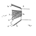
- illustrated lighting device 1 comprises a serving as a light reflector surface structure 8, which is mounted in the illustrated embodiment on a vertical wall of a room.
- Said reflector surface structure 8 comprises a plurality of reflector surface pieces 3 which are integrally formed integrally on a reflector panel 2, in particular formed by an embossing of a metal, in particular aluminum sheet or its surface.
- the said structure 2 may in this case form a solid, self-supporting panel, but may also consist of a flexible foil or plastic or platinum body.
- soft structural materials such as a thin rubber mat can be used, in which the reflector surface pieces 3 embossed and can be formed by means of surface coating.
- the reflector surface structure 8 is planar, i. however, the surface areas defined by the reflector structure 3 may also deviate from the planar shape, for example, to be attached to an arcuately curved wall or column or the like.
- the reflector structure 8 can also without adaptation to the underlying building wall, ceiling or the like have a deviating from the planar shape contouring, for example, a relief-like freeform surface to achieve special lighting effects.
- the reflector surface pieces 3 are arranged in a continuous, continuously shaped surface, so that there are no cracks or distortions within the reflector surface piece field.
- the reflector surface structure 8 may consist of a plurality of pyramidal reflector projections 9, which may be formed in the form of an embossment of a metal sheet.
- the pyramidal reflector projections 9 advantageously have differently sized base areas, so that alternate with smaller pyramid projections.
- the pyramidal reflector projections 9 are arranged not linearly distributed, in particular in a dancing arrangement with respect to transversely to the light incident direction lines with different transverse offset thereof.
- the pyramidal reflector projections 9 each have square base surfaces, larger pyramid projections being arranged offset around their lateral surfaces in each case around a smaller pyramid projection.
- the pyramidal reflector projections 9 may also have other base shapes, such as octagons, or hexagons or other regular polygons.
- the pyramidal projections 9 are regular, ie not skewed, ie, the pyramid tip sits perpendicularly over the centroid of the base so that the reflector surface pieces formed by the pyramid flanks have uniform inclinations, ie, all flanks facing one side Pyramidal genus, for example, the larger pyramids, have approximately the same flank angle.
- the smaller and larger pyramid projections can also have the same flank angle to one side.
- the pyramidal reflector projections 9 may have the same height, but advantageously also different heights, in particular if the pyramidal reflector projections 9 have at least approximately similar flank angles and different sized base surfaces.
- flanks facing towards different sides can also have different flank angles, for example such that the flanks pointing downwards have different angles of inclination than the flanks pointing upwards and both, i. upper and lower flanks may in turn have different angles of inclination than the flanks pointing to the right.
- different preferred directions for the directionally reflected light can be generated by respective grinding radiation from different sides.
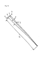
- FIGS. 11 to 15 Further advantageous embodiments of the pyramidal reflector structure show the FIGS. 11 to 15 .
- the goal is better manufacturability, in which tips can be avoided and edges can be made with a duller angle.
- Fig. 11 shows, it can be provided that the tips of the pyramids are flattened or dented. This structure can be illuminated from all four sides to ensure full functionality.
- the pyramids may have a rectangular plan, so that there is a hipped roof-shaped structure.
- the light irradiation can be advantageously only on the long sides, so for example. From the left or right.
- the angles of the four flanks are unchanged as in the previously described pyramids, wherein the pyramids can not be arranged surface-filling, there are free areas on the base.
- the pyramids can also be formed with asymmetrical flanks.
- the pyramids are similar Fig. 13 educated. It is only the left flank of the "pyramid" photometrically active and may still have an angle between 35 ° and 45 ° from the base. Instead of the distance between the pyramids, the flank located in the shadow can be flatter, approx. 25 ° to 35 ° inclined.
- the pyramids or reflector projections may also have other than polygonal, in particular rounded or free-form-like bases, preferably at least one side of the base is formed straight and gem.
- Fig. 14 in particular semicircular base surfaces can be provided. It can be provided that only the plane, gem.
- Fig. 14 each to the left falling flanks are illuminated.
- the flat flanks are oriented towards the same side, possibly with the pre-explained Varaition to a preferred orientation.
- the flat flanks can still have an angle between 35 ° and 45 ° from the base.
- the curved surface is advantageously always in the shade and can remain ineffective photometrically.
- the distance (in both directions) of the "shells" can also be smaller, so that the individual "shells" touch or even intersect. This variant can be implemented particularly favorably because of the advantageous manufacturability.
- angles of the photometrically active surfaces can be randomly varied in order to achieve a slightly different reflected light direction. Both the slope is varied by about +/- 5 °, as well as the Angle of rotation of the structure on the ground plane up to 10 °, as the different representations a, b and c of Fig. 15 demonstrate.
- the reflector surface structure 8 is irradiated by punctiform light sources 7, for example in the form of LEDs, which are arranged on or in the ceiling 6 relatively close to the wall 5 on which the reflector surface piece wallpaper 13 is applied.
- the reflector surface structure 8 can also be illuminated from different sides by a plurality of light sources, wherein the irradiation can take place simultaneously from different sides or alternately from one side or the other in order to achieve different emission characteristics.
- the light sources 7a, 7b and 7c in this case show light sources 7a, which irradiate the reflector surface structure 8 from above, and bottom-side light sources 7c, which can irradiate the reflector surface structure 8 from below and laterally, for example, on an adjacent wall, arranged light sources 7b, through which the reflector surface structure 8 approximately horizontally from the Side ago can be irradiated.
- the light sources 7 advantageously form small points of light with luminous densities L much greater than 10 6 cd / m 2 .
- the light sources 7a, 7b and 7c in the illustrated embodiment are arranged distributed in each case in a row which extends substantially parallel to the wall 5 and thus parallel to the surface defined by the reflector structure 8.
- the arrangement and spacing of the light sources 7 is in this case advantageously such that the surface of the Reflektor vomeriefelds is irradiated at an angle of less than 30 °, ie the light coming from the light sources 7 falls from above onto the reflector surface patch field, the angle to the surface said reflector patch panel in the illustrated embodiment is between 15 ° and 25 °, cf. Fig. 2 ,
- the light sources for example, the ceiling-side light sources 7a, in this case also be formed multi-row, in order to realize different irradiation or light incidence angle to the reflector surface structure 8, cf. FIGS. 1 and 2 ,
- the widening of the light cone coming from the light sources 7 is made such that the entire reflector surface patch field is irradiated, cf. Fig. 2 , wherein in the drawn embodiment and the wall heights provided there and the height of the Reflektor lake Swissefelds a cone widening of 13 ° is provided.
- the arrangement of the light sources 7 - for example, by approaching closer to the wall to be irradiated 5 - made so that the expansion of the light cone is less than 25 °, preferably less than 20 °.
- the arrangement of the LEDs together with the reflector surface pieces cause a light point decomposition, which allows on the one hand a high-contrast perception of the illuminated areas and on the other hand, a substantial glare.
- Each point in the illuminated space is illuminated by several separately perceptible points of light.
- the arrangement of the LEDs and the reflector surface pieces is made such that they in Fig. 10 satisfies the described relationship, according to which the light spots formed by the output surfaces of the reflector surface pieces 3 in terms of size and arrangement meet the requirements of a meaningful Lichtigezerlegung. This is characterized in that the maximum dimension D of each light spot is defined by the following relationship: D ⁇ 2 ⁇ a ⁇ tan x / 2 .
- b 2 ⁇ a ⁇ tan y / 2 .
- a is the viewing distance measured in meters and y ⁇ 10 angular minutes, where y is the opening angle formed by the adjacent partial light bundles of two luminous surfaces.
- the aforementioned parameters B and K are sufficiently unequal to each other.
- the parameter B is selected as a function of the illumination intensity to be determined in the viewing distance a, where the glare effect influences the glare, wherein preferably the parameter B ⁇ 5, in particular B ⁇ 4.
- a light scattering surface structure 30 may be applied to the reflector panel 2, in particular in the form of a textile structure 31, for example in the form of a fabric or a textile flocking.
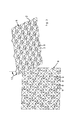
- the textile structure 31 may consist of a mesh-like tissue, which consists of intersecting threads, between which more or less large recesses are provided, the embodiment of Fig. 8 shows in the partial views (a), (b) and (c) different possible mesh sizes and different thread sizes.
- the textile structure 31 can also realize non-linear structures, as is Fig. 9 shows, for example, by textile flocking certain areas of the reflector surface structure 8.
- Fig. 9 shows, for example, by textile flocking certain areas of the reflector surface structure 8.
- the embodiment according to Fig. 9 shows in the partial view (a) and the partial view (b) two different floral or ornamental patterns in which alternate areas of light-scattering material with exposed, ie not flocked areas.
- the textile structure 31 is advantageously raised.
- the filaments or scattering material regions 32 project from the reflector surface structure 8 and have a specific height H with respect to the reflector surface structure 8, which has an influence on the visibility and irradiability of the reflector surface pieces exposed between the scattering material regions 32.
- the stated visibility and irradiability of the exposed reflector surface regions is furthermore influenced by the spacing d between two adjacent scatter material regions 32 or their thickness D measured parallel to the plane of the reflector surface structure.
- this critical angle ⁇ arctg (d / H) in the range between about 60 ° - 90 ° can be adjusted.
- FIG. 5 illustrates this property of the light-scattering surface structure 30 can be used to control the emission of the reflected light by the reflector and textile structure is irradiated at varying angles of incidence of light, for example, two light sources 7aa and 7ab, the cover side different far away from the Level of the reflector surface structure can be arranged. If the two light sources are assigned a control device 40 by means of which the light sources can be variably dimmed, the scattered light component and the proportion of reflected light can be adjusted variably.
Landscapes
- Engineering & Computer Science (AREA)
- General Engineering & Computer Science (AREA)
- Non-Portable Lighting Devices Or Systems Thereof (AREA)
Applications Claiming Priority (1)
| Application Number | Priority Date | Filing Date | Title |
|---|---|---|---|
| DE102012012649.2A DE102012012649A1 (de) | 2012-06-26 | 2012-06-26 | Beleuchtungsvorrichtung |
Publications (3)
| Publication Number | Publication Date |
|---|---|
| EP2679889A2 true EP2679889A2 (fr) | 2014-01-01 |
| EP2679889A3 EP2679889A3 (fr) | 2014-01-22 |
| EP2679889B1 EP2679889B1 (fr) | 2016-01-13 |
Family
ID=48740794
Family Applications (1)
| Application Number | Title | Priority Date | Filing Date |
|---|---|---|---|
| EP13003257.6A Not-in-force EP2679889B1 (fr) | 2012-06-26 | 2013-06-26 | Dispositif d'éclairage |
Country Status (2)
| Country | Link |
|---|---|
| EP (1) | EP2679889B1 (fr) |
| DE (1) | DE102012012649A1 (fr) |
Cited By (2)
| Publication number | Priority date | Publication date | Assignee | Title |
|---|---|---|---|---|
| CN112752875A (zh) * | 2018-10-12 | 2021-05-04 | 特吕茨施勒有限及两合公司 | 用于纺织设备的照明设备和配设有照明设备的纺织设备 |
| EP3896331A1 (fr) * | 2020-01-31 | 2021-10-20 | Bartenbach Holding GmbH | Dispositif d'éclairage |
Families Citing this family (1)
| Publication number | Priority date | Publication date | Assignee | Title |
|---|---|---|---|---|
| DE102015211633A1 (de) * | 2015-06-23 | 2016-12-29 | Lichtraeume Gercek und Muralter GbR (vertretungsberechtigte Gesellschafter: Fatih Gercek, 10179 Berlin; Susana Ferreras-Diaz, 10779 Berlin) | Beleuchtungseinheit und Beleuchtungssystem |
Citations (2)
| Publication number | Priority date | Publication date | Assignee | Title |
|---|---|---|---|---|
| DE3027400A1 (de) | 1980-07-19 | 1982-02-18 | Herman Miller Inc., Zeeland, Mich. | Opto-akustisches paneel |
| DE29724321U1 (de) | 1996-06-14 | 2000-11-09 | Bartenbach, Christian, Aldrans, Tirol | Beleuchtungseinrichtung |
Family Cites Families (13)
| Publication number | Priority date | Publication date | Assignee | Title |
|---|---|---|---|---|
| CA1321988C (fr) * | 1988-10-11 | 1993-09-07 | Jeffrey J. Melby | Appareil d'eclairage |
| DE4039291A1 (de) * | 1990-12-08 | 1992-06-11 | Minnesota Mining & Mfg | Leuchtbox |
| US6002829A (en) * | 1992-03-23 | 1999-12-14 | Minnesota Mining And Manufacturing Company | Luminaire device |
| US6845212B2 (en) * | 1999-10-08 | 2005-01-18 | 3M Innovative Properties Company | Optical element having programmed optical structures |
| US6808294B2 (en) * | 2002-10-18 | 2004-10-26 | The L. D. Kichler Co. | Collapsible lampshade |
| GB2405461B (en) * | 2003-08-30 | 2006-01-11 | Pulsar Light Of Cambridge Ltd | Lighting panel |
| DE102006011529A1 (de) * | 2006-03-10 | 2007-09-13 | Manfred Kluth | Lichtdurchlässiges Material für ein Beleuchtungselement |
| DE102006013856A1 (de) * | 2006-03-23 | 2007-10-04 | Frank Zeller | Vorrichtung zur Erzeugung von weichem und gleichzeitig gerichtetem Licht |
| FR2907194B1 (fr) * | 2006-10-13 | 2010-08-27 | Cedric Brochier Soieries | Complexe eclairant comportant une source lumineuse presentant une nappe de fibres optiques |
| US7661847B2 (en) * | 2006-12-22 | 2010-02-16 | Jessica Wang | Formed lighting fixture having a fibrous layer |
| DE102007020397B8 (de) * | 2007-04-27 | 2012-08-30 | Bombardier Transportation Gmbh | Beleuchtungsvorrichtung für die Beleuchtung von Fahrzeuginnenräumen |
| WO2009007927A1 (fr) * | 2007-07-11 | 2009-01-15 | Koninklijke Philips Electronics N.V. | Procédé d'éclairage d'au moins une partie d'un espace et système d'éclairage destiné à être utilisé dans ce procédé |
| DE102010048125A1 (de) * | 2010-10-11 | 2012-04-12 | Bartenbach Holding Gmbh | Beleuchtungsvorrichtung |
-
2012
- 2012-06-26 DE DE102012012649.2A patent/DE102012012649A1/de not_active Withdrawn
-
2013
- 2013-06-26 EP EP13003257.6A patent/EP2679889B1/fr not_active Not-in-force
Patent Citations (2)
| Publication number | Priority date | Publication date | Assignee | Title |
|---|---|---|---|---|
| DE3027400A1 (de) | 1980-07-19 | 1982-02-18 | Herman Miller Inc., Zeeland, Mich. | Opto-akustisches paneel |
| DE29724321U1 (de) | 1996-06-14 | 2000-11-09 | Bartenbach, Christian, Aldrans, Tirol | Beleuchtungseinrichtung |
Cited By (3)
| Publication number | Priority date | Publication date | Assignee | Title |
|---|---|---|---|---|
| CN112752875A (zh) * | 2018-10-12 | 2021-05-04 | 特吕茨施勒有限及两合公司 | 用于纺织设备的照明设备和配设有照明设备的纺织设备 |
| CN112752875B (zh) * | 2018-10-12 | 2023-04-07 | 特吕茨施勒集团欧洲公司 | 用于纺织设备的照明设备和配设有照明设备的纺织设备 |
| EP3896331A1 (fr) * | 2020-01-31 | 2021-10-20 | Bartenbach Holding GmbH | Dispositif d'éclairage |
Also Published As
| Publication number | Publication date |
|---|---|
| EP2679889A3 (fr) | 2014-01-22 |
| EP2679889B1 (fr) | 2016-01-13 |
| DE102012012649A1 (de) | 2014-01-16 |
Similar Documents
| Publication | Publication Date | Title |
|---|---|---|
| DE2124021A1 (fr) | ||
| EP2679889B1 (fr) | Dispositif d'éclairage | |
| EP2880361B1 (fr) | Dispositif d'éclairage | |
| EP2679888B1 (fr) | Dispositif d'éclairage | |
| EP2439443B1 (fr) | Dispositif d'éclairage | |
| EP3408584B1 (fr) | Appareil d'éclairage muni d'un élément de recouvrement pyramidal ou conique | |
| EP2116761A1 (fr) | Dispositif d'éclairage de façades et pulvérisateur de façades correspondant | |
| AT513468B1 (de) | Beleuchtbares Fassadenpaneel | |
| EP0582832B1 (fr) | Elément réflécteur et arrangement de ces éléments pour l'éclairage indirect de locaux de bâtiments | |
| DE102016201347B4 (de) | Optisches System zum Beeinflussen der Lichtabgabe einer Lichtquelle | |
| WO2015055693A1 (fr) | Système optique pour source lumineuse à led ainsi que lampe équipée d'un tel système optique | |
| DE102013206850A1 (de) | Zur Erzeugung einer Signal-Lichtverteilung eingerichtetes Lichtmodul einer Kraftfahrzeugbeleuchtungseinrichtung | |
| EP0813026A2 (fr) | Dispositif d'éclairage | |
| EP2230448A1 (fr) | Cascade de miroirs à DEL | |
| DE102006019202A1 (de) | Flachleuchte zur Ausstrahlung von Licht in einer bauformabhängigen Richtung mit bauformabhängigem Helligkeitsprofil | |
| EP3745020A1 (fr) | Luminaire | |
| EP1900998B1 (fr) | Réflecteur doté d'une structure émettant de la lumière | |
| EP3919808B1 (fr) | Luminaire | |
| WO2008040690A1 (fr) | Module lumineux à diode électroluminescente avec récepteur | |
| EP2860444B1 (fr) | Spot à grille à LED | |
| DE29724321U1 (de) | Beleuchtungseinrichtung | |
| DE202013105863U1 (de) | Anordnung zum Entblenden der Lichtabgabe | |
| DE102009006167A1 (de) | Längliches Leuchten-Element und damit beleuchtetes Paneel | |
| EP2076897A1 (fr) | Module lumineux à diode électroluminescente avec récepteur | |
| DE19945692A1 (de) | Reflektor für eine Reflektorleuchte und Leuchte |
Legal Events
| Date | Code | Title | Description |
|---|---|---|---|
| PUAL | Search report despatched |
Free format text: ORIGINAL CODE: 0009013 |
|
| PUAI | Public reference made under article 153(3) epc to a published international application that has entered the european phase |
Free format text: ORIGINAL CODE: 0009012 |
|
| AK | Designated contracting states |
Kind code of ref document: A2 Designated state(s): AL AT BE BG CH CY CZ DE DK EE ES FI FR GB GR HR HU IE IS IT LI LT LU LV MC MK MT NL NO PL PT RO RS SE SI SK SM TR |
|
| AX | Request for extension of the european patent |
Extension state: BA ME |
|
| AK | Designated contracting states |
Kind code of ref document: A3 Designated state(s): AL AT BE BG CH CY CZ DE DK EE ES FI FR GB GR HR HU IE IS IT LI LT LU LV MC MK MT NL NO PL PT RO RS SE SI SK SM TR |
|
| AX | Request for extension of the european patent |
Extension state: BA ME |
|
| RIC1 | Information provided on ipc code assigned before grant |
Ipc: F21V 7/22 20060101ALI20131216BHEP Ipc: F21S 8/00 20060101ALN20131216BHEP Ipc: F21Y 101/02 20060101ALN20131216BHEP Ipc: F21V 7/00 20060101AFI20131216BHEP Ipc: F21V 7/04 20060101ALI20131216BHEP Ipc: F21V 7/05 20060101ALI20131216BHEP |
|
| 17P | Request for examination filed |
Effective date: 20140721 |
|
| RIC1 | Information provided on ipc code assigned before grant |
Ipc: F21V 7/05 20060101ALI20150604BHEP Ipc: F21Y 101/02 20060101ALN20150604BHEP Ipc: F21V 7/00 20060101AFI20150604BHEP Ipc: F21V 7/04 20060101ALI20150604BHEP Ipc: F21V 7/22 20060101ALI20150604BHEP Ipc: F21S 8/00 20060101ALN20150604BHEP |
|
| GRAP | Despatch of communication of intention to grant a patent |
Free format text: ORIGINAL CODE: EPIDOSNIGR1 |
|
| RIC1 | Information provided on ipc code assigned before grant |
Ipc: F21V 7/00 20060101AFI20150701BHEP Ipc: F21S 8/00 20060101ALN20150701BHEP Ipc: F21V 7/05 20060101ALI20150701BHEP Ipc: F21V 7/04 20060101ALI20150701BHEP Ipc: F21V 7/22 20060101ALI20150701BHEP Ipc: F21Y 101/02 20060101ALN20150701BHEP |
|
| INTG | Intention to grant announced |
Effective date: 20150717 |
|
| GRAS | Grant fee paid |
Free format text: ORIGINAL CODE: EPIDOSNIGR3 |
|
| GRAA | (expected) grant |
Free format text: ORIGINAL CODE: 0009210 |
|
| AK | Designated contracting states |
Kind code of ref document: B1 Designated state(s): AL AT BE BG CH CY CZ DE DK EE ES FI FR GB GR HR HU IE IS IT LI LT LU LV MC MK MT NL NO PL PT RO RS SE SI SK SM TR |
|
| REG | Reference to a national code |
Ref country code: GB Ref legal event code: FG4D Free format text: NOT ENGLISH |
|
| REG | Reference to a national code |
Ref country code: CH Ref legal event code: EP |
|
| REG | Reference to a national code |
Ref country code: IE Ref legal event code: FG4D Free format text: LANGUAGE OF EP DOCUMENT: GERMAN |
|
| REG | Reference to a national code |
Ref country code: AT Ref legal event code: REF Ref document number: 770770 Country of ref document: AT Kind code of ref document: T Effective date: 20160215 |
|
| REG | Reference to a national code |
Ref country code: DE Ref legal event code: R096 Ref document number: 502013001769 Country of ref document: DE |
|
| REG | Reference to a national code |
Ref country code: LT Ref legal event code: MG4D |
|
| REG | Reference to a national code |
Ref country code: NL Ref legal event code: MP Effective date: 20160113 |
|
| PG25 | Lapsed in a contracting state [announced via postgrant information from national office to epo] |
Ref country code: NL Free format text: LAPSE BECAUSE OF FAILURE TO SUBMIT A TRANSLATION OF THE DESCRIPTION OR TO PAY THE FEE WITHIN THE PRESCRIBED TIME-LIMIT Effective date: 20160113 |
|
| PG25 | Lapsed in a contracting state [announced via postgrant information from national office to epo] |
Ref country code: FI Free format text: LAPSE BECAUSE OF FAILURE TO SUBMIT A TRANSLATION OF THE DESCRIPTION OR TO PAY THE FEE WITHIN THE PRESCRIBED TIME-LIMIT Effective date: 20160113 Ref country code: ES Free format text: LAPSE BECAUSE OF FAILURE TO SUBMIT A TRANSLATION OF THE DESCRIPTION OR TO PAY THE FEE WITHIN THE PRESCRIBED TIME-LIMIT Effective date: 20160113 Ref country code: HR Free format text: LAPSE BECAUSE OF FAILURE TO SUBMIT A TRANSLATION OF THE DESCRIPTION OR TO PAY THE FEE WITHIN THE PRESCRIBED TIME-LIMIT Effective date: 20160113 Ref country code: GR Free format text: LAPSE BECAUSE OF FAILURE TO SUBMIT A TRANSLATION OF THE DESCRIPTION OR TO PAY THE FEE WITHIN THE PRESCRIBED TIME-LIMIT Effective date: 20160414 Ref country code: IT Free format text: LAPSE BECAUSE OF FAILURE TO SUBMIT A TRANSLATION OF THE DESCRIPTION OR TO PAY THE FEE WITHIN THE PRESCRIBED TIME-LIMIT Effective date: 20160113 Ref country code: NO Free format text: LAPSE BECAUSE OF FAILURE TO SUBMIT A TRANSLATION OF THE DESCRIPTION OR TO PAY THE FEE WITHIN THE PRESCRIBED TIME-LIMIT Effective date: 20160413 |
|
| PG25 | Lapsed in a contracting state [announced via postgrant information from national office to epo] |
Ref country code: IS Free format text: LAPSE BECAUSE OF FAILURE TO SUBMIT A TRANSLATION OF THE DESCRIPTION OR TO PAY THE FEE WITHIN THE PRESCRIBED TIME-LIMIT Effective date: 20160513 Ref country code: PL Free format text: LAPSE BECAUSE OF FAILURE TO SUBMIT A TRANSLATION OF THE DESCRIPTION OR TO PAY THE FEE WITHIN THE PRESCRIBED TIME-LIMIT Effective date: 20160113 Ref country code: RS Free format text: LAPSE BECAUSE OF FAILURE TO SUBMIT A TRANSLATION OF THE DESCRIPTION OR TO PAY THE FEE WITHIN THE PRESCRIBED TIME-LIMIT Effective date: 20160113 Ref country code: PT Free format text: LAPSE BECAUSE OF FAILURE TO SUBMIT A TRANSLATION OF THE DESCRIPTION OR TO PAY THE FEE WITHIN THE PRESCRIBED TIME-LIMIT Effective date: 20160513 Ref country code: SE Free format text: LAPSE BECAUSE OF FAILURE TO SUBMIT A TRANSLATION OF THE DESCRIPTION OR TO PAY THE FEE WITHIN THE PRESCRIBED TIME-LIMIT Effective date: 20160113 Ref country code: LV Free format text: LAPSE BECAUSE OF FAILURE TO SUBMIT A TRANSLATION OF THE DESCRIPTION OR TO PAY THE FEE WITHIN THE PRESCRIBED TIME-LIMIT Effective date: 20160113 Ref country code: LT Free format text: LAPSE BECAUSE OF FAILURE TO SUBMIT A TRANSLATION OF THE DESCRIPTION OR TO PAY THE FEE WITHIN THE PRESCRIBED TIME-LIMIT Effective date: 20160113 |
|
| REG | Reference to a national code |
Ref country code: DE Ref legal event code: R097 Ref document number: 502013001769 Country of ref document: DE |
|
| PG25 | Lapsed in a contracting state [announced via postgrant information from national office to epo] |
Ref country code: EE Free format text: LAPSE BECAUSE OF FAILURE TO SUBMIT A TRANSLATION OF THE DESCRIPTION OR TO PAY THE FEE WITHIN THE PRESCRIBED TIME-LIMIT Effective date: 20160113 Ref country code: DK Free format text: LAPSE BECAUSE OF FAILURE TO SUBMIT A TRANSLATION OF THE DESCRIPTION OR TO PAY THE FEE WITHIN THE PRESCRIBED TIME-LIMIT Effective date: 20160113 |
|
| PLBE | No opposition filed within time limit |
Free format text: ORIGINAL CODE: 0009261 |
|
| STAA | Information on the status of an ep patent application or granted ep patent |
Free format text: STATUS: NO OPPOSITION FILED WITHIN TIME LIMIT |
|
| PG25 | Lapsed in a contracting state [announced via postgrant information from national office to epo] |
Ref country code: SM Free format text: LAPSE BECAUSE OF FAILURE TO SUBMIT A TRANSLATION OF THE DESCRIPTION OR TO PAY THE FEE WITHIN THE PRESCRIBED TIME-LIMIT Effective date: 20160113 Ref country code: SK Free format text: LAPSE BECAUSE OF FAILURE TO SUBMIT A TRANSLATION OF THE DESCRIPTION OR TO PAY THE FEE WITHIN THE PRESCRIBED TIME-LIMIT Effective date: 20160113 Ref country code: CZ Free format text: LAPSE BECAUSE OF FAILURE TO SUBMIT A TRANSLATION OF THE DESCRIPTION OR TO PAY THE FEE WITHIN THE PRESCRIBED TIME-LIMIT Effective date: 20160113 Ref country code: RO Free format text: LAPSE BECAUSE OF FAILURE TO SUBMIT A TRANSLATION OF THE DESCRIPTION OR TO PAY THE FEE WITHIN THE PRESCRIBED TIME-LIMIT Effective date: 20160113 |
|
| 26N | No opposition filed |
Effective date: 20161014 |
|
| PG25 | Lapsed in a contracting state [announced via postgrant information from national office to epo] |
Ref country code: BE Free format text: LAPSE BECAUSE OF NON-PAYMENT OF DUE FEES Effective date: 20160630 |
|
| PG25 | Lapsed in a contracting state [announced via postgrant information from national office to epo] |
Ref country code: MC Free format text: LAPSE BECAUSE OF FAILURE TO SUBMIT A TRANSLATION OF THE DESCRIPTION OR TO PAY THE FEE WITHIN THE PRESCRIBED TIME-LIMIT Effective date: 20160113 |
|
| REG | Reference to a national code |
Ref country code: CH Ref legal event code: PL |
|
| PG25 | Lapsed in a contracting state [announced via postgrant information from national office to epo] |
Ref country code: BG Free format text: LAPSE BECAUSE OF FAILURE TO SUBMIT A TRANSLATION OF THE DESCRIPTION OR TO PAY THE FEE WITHIN THE PRESCRIBED TIME-LIMIT Effective date: 20160413 Ref country code: SI Free format text: LAPSE BECAUSE OF FAILURE TO SUBMIT A TRANSLATION OF THE DESCRIPTION OR TO PAY THE FEE WITHIN THE PRESCRIBED TIME-LIMIT Effective date: 20160113 |
|
| REG | Reference to a national code |
Ref country code: IE Ref legal event code: MM4A |
|
| REG | Reference to a national code |
Ref country code: FR Ref legal event code: ST Effective date: 20170228 |
|
| PG25 | Lapsed in a contracting state [announced via postgrant information from national office to epo] |
Ref country code: CH Free format text: LAPSE BECAUSE OF NON-PAYMENT OF DUE FEES Effective date: 20160630 Ref country code: LI Free format text: LAPSE BECAUSE OF NON-PAYMENT OF DUE FEES Effective date: 20160630 Ref country code: FR Free format text: LAPSE BECAUSE OF NON-PAYMENT OF DUE FEES Effective date: 20160630 |
|
| PG25 | Lapsed in a contracting state [announced via postgrant information from national office to epo] |
Ref country code: IE Free format text: LAPSE BECAUSE OF NON-PAYMENT OF DUE FEES Effective date: 20160626 |
|
| GBPC | Gb: european patent ceased through non-payment of renewal fee |
Effective date: 20170626 |
|
| PG25 | Lapsed in a contracting state [announced via postgrant information from national office to epo] |
Ref country code: GB Free format text: LAPSE BECAUSE OF NON-PAYMENT OF DUE FEES Effective date: 20170626 |
|
| PG25 | Lapsed in a contracting state [announced via postgrant information from national office to epo] |
Ref country code: CY Free format text: LAPSE BECAUSE OF FAILURE TO SUBMIT A TRANSLATION OF THE DESCRIPTION OR TO PAY THE FEE WITHIN THE PRESCRIBED TIME-LIMIT Effective date: 20160113 Ref country code: HU Free format text: LAPSE BECAUSE OF FAILURE TO SUBMIT A TRANSLATION OF THE DESCRIPTION OR TO PAY THE FEE WITHIN THE PRESCRIBED TIME-LIMIT; INVALID AB INITIO Effective date: 20130626 |
|
| PG25 | Lapsed in a contracting state [announced via postgrant information from national office to epo] |
Ref country code: MK Free format text: LAPSE BECAUSE OF FAILURE TO SUBMIT A TRANSLATION OF THE DESCRIPTION OR TO PAY THE FEE WITHIN THE PRESCRIBED TIME-LIMIT Effective date: 20160113 Ref country code: TR Free format text: LAPSE BECAUSE OF FAILURE TO SUBMIT A TRANSLATION OF THE DESCRIPTION OR TO PAY THE FEE WITHIN THE PRESCRIBED TIME-LIMIT Effective date: 20160113 Ref country code: MT Free format text: LAPSE BECAUSE OF FAILURE TO SUBMIT A TRANSLATION OF THE DESCRIPTION OR TO PAY THE FEE WITHIN THE PRESCRIBED TIME-LIMIT Effective date: 20160113 Ref country code: LU Free format text: LAPSE BECAUSE OF NON-PAYMENT OF DUE FEES Effective date: 20160626 |
|
| PG25 | Lapsed in a contracting state [announced via postgrant information from national office to epo] |
Ref country code: AL Free format text: LAPSE BECAUSE OF FAILURE TO SUBMIT A TRANSLATION OF THE DESCRIPTION OR TO PAY THE FEE WITHIN THE PRESCRIBED TIME-LIMIT Effective date: 20160113 |
|
| RIC2 | Information provided on ipc code assigned after grant |
Ipc: F21V 7/22 20180101ALI20150701BHEP Ipc: F21S 8/00 20060101ALN20150701BHEP Ipc: F21V 7/04 20060101ALI20150701BHEP Ipc: F21V 7/00 20060101AFI20150701BHEP Ipc: F21Y 101/02 20000101ALN20150701BHEP Ipc: F21V 7/05 20060101ALI20150701BHEP |
|
| PGFP | Annual fee paid to national office [announced via postgrant information from national office to epo] |
Ref country code: DE Payment date: 20190628 Year of fee payment: 7 Ref country code: AT Payment date: 20190625 Year of fee payment: 7 |
|
| REG | Reference to a national code |
Ref country code: DE Ref legal event code: R119 Ref document number: 502013001769 Country of ref document: DE |
|
| REG | Reference to a national code |
Ref country code: AT Ref legal event code: MM01 Ref document number: 770770 Country of ref document: AT Kind code of ref document: T Effective date: 20200626 |
|
| PG25 | Lapsed in a contracting state [announced via postgrant information from national office to epo] |
Ref country code: DE Free format text: LAPSE BECAUSE OF NON-PAYMENT OF DUE FEES Effective date: 20210101 Ref country code: AT Free format text: LAPSE BECAUSE OF NON-PAYMENT OF DUE FEES Effective date: 20200626 |