EP2230488A1 - Kalibrierung zur Verbesserung der Positionierungsbestimmung eines Wetterradars - Google Patents
Kalibrierung zur Verbesserung der Positionierungsbestimmung eines Wetterradars Download PDFInfo
- Publication number
- EP2230488A1 EP2230488A1 EP10153557A EP10153557A EP2230488A1 EP 2230488 A1 EP2230488 A1 EP 2230488A1 EP 10153557 A EP10153557 A EP 10153557A EP 10153557 A EP10153557 A EP 10153557A EP 2230488 A1 EP2230488 A1 EP 2230488A1
- Authority
- EP
- European Patent Office
- Prior art keywords
- gimbal
- angular position
- angle sensor
- data set
- rotated
- Prior art date
- Legal status (The legal status is an assumption and is not a legal conclusion. Google has not performed a legal analysis and makes no representation as to the accuracy of the status listed.)
- Withdrawn
Links
- 238000000034 method Methods 0.000 claims abstract description 14
- 238000001514 detection method Methods 0.000 claims abstract description 4
- 238000012545 processing Methods 0.000 claims description 8
- 230000003287 optical effect Effects 0.000 claims description 6
- 238000013459 approach Methods 0.000 description 5
- 230000000694 effects Effects 0.000 description 5
- 238000005259 measurement Methods 0.000 description 4
- 238000010276 construction Methods 0.000 description 1
- 238000012544 monitoring process Methods 0.000 description 1
Images



Classifications
-
- G—PHYSICS
- G01—MEASURING; TESTING
- G01S—RADIO DIRECTION-FINDING; RADIO NAVIGATION; DETERMINING DISTANCE OR VELOCITY BY USE OF RADIO WAVES; LOCATING OR PRESENCE-DETECTING BY USE OF THE REFLECTION OR RERADIATION OF RADIO WAVES; ANALOGOUS ARRANGEMENTS USING OTHER WAVES
- G01S13/00—Systems using the reflection or reradiation of radio waves, e.g. radar systems; Analogous systems using reflection or reradiation of waves whose nature or wavelength is irrelevant or unspecified
- G01S13/88—Radar or analogous systems specially adapted for specific applications
- G01S13/95—Radar or analogous systems specially adapted for specific applications for meteorological use
- G01S13/953—Radar or analogous systems specially adapted for specific applications for meteorological use mounted on aircraft
-
- G—PHYSICS
- G01—MEASURING; TESTING
- G01D—MEASURING NOT SPECIALLY ADAPTED FOR A SPECIFIC VARIABLE; ARRANGEMENTS FOR MEASURING TWO OR MORE VARIABLES NOT COVERED IN A SINGLE OTHER SUBCLASS; TARIFF METERING APPARATUS; MEASURING OR TESTING NOT OTHERWISE PROVIDED FOR
- G01D1/00—Measuring arrangements giving results other than momentary value of variable, of general application
-
- G—PHYSICS
- G01—MEASURING; TESTING
- G01D—MEASURING NOT SPECIALLY ADAPTED FOR A SPECIFIC VARIABLE; ARRANGEMENTS FOR MEASURING TWO OR MORE VARIABLES NOT COVERED IN A SINGLE OTHER SUBCLASS; TARIFF METERING APPARATUS; MEASURING OR TESTING NOT OTHERWISE PROVIDED FOR
- G01D15/00—Component parts of recorders for measuring arrangements not specially adapted for a specific variable
-
- G—PHYSICS
- G01—MEASURING; TESTING
- G01D—MEASURING NOT SPECIALLY ADAPTED FOR A SPECIFIC VARIABLE; ARRANGEMENTS FOR MEASURING TWO OR MORE VARIABLES NOT COVERED IN A SINGLE OTHER SUBCLASS; TARIFF METERING APPARATUS; MEASURING OR TESTING NOT OTHERWISE PROVIDED FOR
- G01D21/00—Measuring or testing not otherwise provided for
-
- G—PHYSICS
- G01—MEASURING; TESTING
- G01S—RADIO DIRECTION-FINDING; RADIO NAVIGATION; DETERMINING DISTANCE OR VELOCITY BY USE OF RADIO WAVES; LOCATING OR PRESENCE-DETECTING BY USE OF THE REFLECTION OR RERADIATION OF RADIO WAVES; ANALOGOUS ARRANGEMENTS USING OTHER WAVES
- G01S7/00—Details of systems according to groups G01S13/00, G01S15/00, G01S17/00
- G01S7/02—Details of systems according to groups G01S13/00, G01S15/00, G01S17/00 of systems according to group G01S13/00
- G01S7/40—Means for monitoring or calibrating
- G01S7/4004—Means for monitoring or calibrating of parts of a radar system
- G01S7/4026—Antenna boresight
-
- G—PHYSICS
- G01—MEASURING; TESTING
- G01S—RADIO DIRECTION-FINDING; RADIO NAVIGATION; DETERMINING DISTANCE OR VELOCITY BY USE OF RADIO WAVES; LOCATING OR PRESENCE-DETECTING BY USE OF THE REFLECTION OR RERADIATION OF RADIO WAVES; ANALOGOUS ARRANGEMENTS USING OTHER WAVES
- G01S7/00—Details of systems according to groups G01S13/00, G01S15/00, G01S17/00
- G01S7/02—Details of systems according to groups G01S13/00, G01S15/00, G01S17/00 of systems according to group G01S13/00
- G01S7/40—Means for monitoring or calibrating
- G01S7/4004—Means for monitoring or calibrating of parts of a radar system
- G01S7/4026—Antenna boresight
- G01S7/4034—Antenna boresight in elevation, i.e. in the vertical plane
-
- G—PHYSICS
- G01—MEASURING; TESTING
- G01S—RADIO DIRECTION-FINDING; RADIO NAVIGATION; DETERMINING DISTANCE OR VELOCITY BY USE OF RADIO WAVES; LOCATING OR PRESENCE-DETECTING BY USE OF THE REFLECTION OR RERADIATION OF RADIO WAVES; ANALOGOUS ARRANGEMENTS USING OTHER WAVES
- G01S7/00—Details of systems according to groups G01S13/00, G01S15/00, G01S17/00
- G01S7/02—Details of systems according to groups G01S13/00, G01S15/00, G01S17/00 of systems according to group G01S13/00
- G01S7/40—Means for monitoring or calibrating
- G01S7/4004—Means for monitoring or calibrating of parts of a radar system
- G01S7/4026—Antenna boresight
- G01S7/403—Antenna boresight in azimuth, i.e. in the horizontal plane
-
- G—PHYSICS
- G01—MEASURING; TESTING
- G01S—RADIO DIRECTION-FINDING; RADIO NAVIGATION; DETERMINING DISTANCE OR VELOCITY BY USE OF RADIO WAVES; LOCATING OR PRESENCE-DETECTING BY USE OF THE REFLECTION OR RERADIATION OF RADIO WAVES; ANALOGOUS ARRANGEMENTS USING OTHER WAVES
- G01S7/00—Details of systems according to groups G01S13/00, G01S15/00, G01S17/00
- G01S7/48—Details of systems according to groups G01S13/00, G01S15/00, G01S17/00 of systems according to group G01S17/00
- G01S7/497—Means for monitoring or calibrating
- G01S7/4972—Alignment of sensor
-
- Y—GENERAL TAGGING OF NEW TECHNOLOGICAL DEVELOPMENTS; GENERAL TAGGING OF CROSS-SECTIONAL TECHNOLOGIES SPANNING OVER SEVERAL SECTIONS OF THE IPC; TECHNICAL SUBJECTS COVERED BY FORMER USPC CROSS-REFERENCE ART COLLECTIONS [XRACs] AND DIGESTS
- Y02—TECHNOLOGIES OR APPLICATIONS FOR MITIGATION OR ADAPTATION AGAINST CLIMATE CHANGE
- Y02A—TECHNOLOGIES FOR ADAPTATION TO CLIMATE CHANGE
- Y02A90/00—Technologies having an indirect contribution to adaptation to climate change
- Y02A90/10—Information and communication technologies [ICT] supporting adaptation to climate change, e.g. for weather forecasting or climate simulation
Definitions
- FIG. 1 illustrates an exemplary dual-axis radar-scanning assembly 10.
- the assembly 10 includes a base member 20 supporting a first gimbal 30, which rotates about an axis x, and a second gimbal 40, which rotates about an axis y generally perpendicular to axis x.
- a frame 50 which is configured to support an antenna sensor (not shown in Figure 1 ), may be mounted to the first gimbal 30, so as to be rotated in a two-dimensional scan field by the gimbals 30, 40.
- the assembly may include one or more resolvers (not shown in Figure 1 ) functioning to provide signals indicating the angular position of the gimbals 30, 40.
- the reported position has a defined amount of error associated with it.
- High-precision angular sensors are very costly and would impact the unit cost and marketability of the radar system.
- simple calibration procedures such as using a digital protractor, have been used to define the zero position (boresight) of a single-axis or multiple-axes antenna-gimbal assembly. This is a one-point calibration approach that typically does not provide a sufficient level of calibration accuracy. As such, it would be advantageous to use lower-cost sensors, with their typically lower-precision capability, with high-precision results.
- a method of calibrating antenna-position detection associated with a radar system includes mounting a second angle sensor to the first gimbal configured to detect an angular position of the first gimbal.
- the first gimbal is rotated through each angular position of a set of the angular positions.
- a first set of data is generated with the first angle sensor that characterizes a detected angular position of the first gimbal.
- a second set of data is generated with the second angle sensor that characterizes a detected angular position of the first gimbal.
- a third data set is determined comprising differences, between the first and second data sets, in detected angular position at each first-gimbal angular position.
- the third data set is stored in a memory device.
- Figure 1 illustrates an exemplary conventional dual-axis radar-scanning assembly
- Figure 2 illustrates an approach to calibrating a dual-axis radar-scanning assembly according to an embodiment of the invention
- Figure 3 illustrates a radar system according to an embodiment
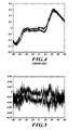
- Figures 4-7 illustrate the effect of the calibration procedure of an embodiment on a radar system.
- the lesser precision sensor is "characterized" with a higher precision sensor
- the resultant data is stored onboard the radar system (e.g., in a database) and the data is used to improve the system level precision.
- Sensor construction and assembly in a higher-level system dictate the level of precision the sensor is capable of. These effects are typically repeatable throughout the scan region of the radar antenna. Where a repeatable error exists, a higher precision sensor would be able to measure that error thoughout the scan region and the data representing such error stored for later use.
- an encoder of a higher precision, is used to measure the error of the resolvers used in the antenna positioner.
- the encoder measures error during calibration of the antenna scanning assembly to provide data that can be used onboard the radar system to compensate for the error, so as to provide onboard a true orientation of the resolvers, as measured during calibration, in relation to the erroneous orientation reported onboard by the resolvers.
- An embodiment includes a method of improving position-control accuracy of a weather-radar antenna control system through calibration.
- An embodiment includes a calibration system, used to characterize the target system, and associated software components required to download and apply calibration data in the target system.
- the target system, calibration system and software components provide a method of improving system performance by compensating for deterministic position feedback error introduced by, for example, structural elements and position feedback sensors.
- FIG 2 illustrated is an approach, according to an embodiment, to calibrating a dual-axis radar-scanning assembly 15, similar to assembly 10 illustrated in Figure 1 , in which like elements are designated by like reference numerals.
- the approach illustrated in Figure 2 includes calibrating antenna-position detection associated with the assembly 15, which is to be part of a radar system 300 ( Figure 3 ).
- the first and second gimbals 30, 40 are configured to rotate through a respective range of angular positions.
- Angle sensors associated with the assembly 15, such as resolvers 320, 330 ( Figure 3 ), are configured to detect the angular positions of the first and second gimbals 30, 40.
- the illustrated approach includes mounting high-precision angle sensors, such as optical-encoder sensors 60, 70, to end portions of the first gimbal 30 and second gimbal 40, respectively.
- the encoder sensors 60, 70 are configured to detect respective angular positions of the first and second gimbals 30, 40.
- the optical encoders 60, 70, and associated components, employed in an embodiment may include, or be similar in functionality to, the sensor system having model number L-9517-9155-02A produced by RENISHAW ® .
- a sensor-ring portion of the encoder sensors 60, 70 are mounted onto respective ones of the axes of the end portions of first and second gimbals 30, 40.
- each of the first and second gimbals 30, 40 are rotated through a predetermined set of angular positions.
- first data sets are generated by the resolvers 320, 330 that characterize the detected angular position of the first and second gimbals 30, 40 at each angular position through which they are rotated.
- second data sets are generated by the encoder sensors 60, 70 that characterize the detected angular position of the first and second gimbals 30, 40 at each angular position through which they are rotated.
- first and second data sets are provided to a processing device (not shown) that is configured to determine a third data set characterizing errors in the angular-position measurements provided by the resolvers 320, 330 as determined from the measurements provided by the encoder sensors 60, 70.
- these errors may be characterized as the differences, between the first data set and second data set, in detected angular position at each angular position through which the first and second gimbals 30, 40 are rotated.
- the third data set is subsequently stored in a memory device, such as a database 340 ( Figure 3 ) onboard an aircraft or other vehicle in which the assembly 15 will be deployed.
- the radar system 300 includes the scanning assembly 15 illustrated in Figure 2 , not including the encoder sensors 60, 70.
- the system 300 includes an antenna element 310 mounted to the first and second gimbals 30, 40, the database 340, and a processing element 350.
- the database 340 includes the third data set characterizing errors in the angular-position measurements provided by the resolvers 320, 330 as determined from the measurements provided by the encoder sensors 60, 70.
- the processing element 350 receives from the resolvers 320, 330 detected angular positions of the first and second gimbals 30, 40. Based on the third data set, the processing element 350 determines corrected, and more accurate, angular positions of the first and second gimbals 30, 40.
- These error-compensated determinations are then provided by the processing element 350 to weather-monitoring avionics/electronics (not shown), or the like, aboard the aircraft or other vehicle in which the illustrated system 300 is implemented.
- Figures 4-7 illustrate the effect of the herein-described calibration procedure of an embodiment on a radar system.
- Figures 4-5 show the azimuth-axis effect and Figures 6-7 show the elevation-axis effect.
- the openings are due to latencies in the reporting path and the speed of the antenna commanded.
- the error before optical calibration is ⁇ 0.3°; as shown in Figure 5 , after optical calibration (zero-point cal + optical encoder protocol) the azimuth error is reduced to ⁇ 0.07°.
- the elevation error is similarly affected: as can be seen from Figure 6 , before high-resolution calibration, the error is ⁇ 0.17°; as shown in Figure 7 , after high-resolution calibration, the error is ⁇ 0.06°.
Landscapes
- Engineering & Computer Science (AREA)
- Radar, Positioning & Navigation (AREA)
- Remote Sensing (AREA)
- Physics & Mathematics (AREA)
- General Physics & Mathematics (AREA)
- Computer Networks & Wireless Communication (AREA)
- Aviation & Aerospace Engineering (AREA)
- Electromagnetism (AREA)
- Radar Systems Or Details Thereof (AREA)
Applications Claiming Priority (1)
| Application Number | Priority Date | Filing Date | Title |
|---|---|---|---|
| US12/405,924 US8077080B2 (en) | 2009-03-17 | 2009-03-17 | Calibration to improve weather radar positioning determination |
Publications (1)
| Publication Number | Publication Date |
|---|---|
| EP2230488A1 true EP2230488A1 (de) | 2010-09-22 |
Family
ID=42236443
Family Applications (1)
| Application Number | Title | Priority Date | Filing Date |
|---|---|---|---|
| EP10153557A Withdrawn EP2230488A1 (de) | 2009-03-17 | 2010-02-14 | Kalibrierung zur Verbesserung der Positionierungsbestimmung eines Wetterradars |
Country Status (2)
| Country | Link |
|---|---|
| US (1) | US8077080B2 (de) |
| EP (1) | EP2230488A1 (de) |
Cited By (1)
| Publication number | Priority date | Publication date | Assignee | Title |
|---|---|---|---|---|
| EP2669701A1 (de) | 2012-06-01 | 2013-12-04 | Honeywell International Inc. | Kalibrierung zur Verbesserung der Positionierungsbestimmung eines Wetterradars |
Families Citing this family (7)
| Publication number | Priority date | Publication date | Assignee | Title |
|---|---|---|---|---|
| WO2008148107A1 (en) * | 2007-05-28 | 2008-12-04 | Kossin Philip S | Transmission of uncompressed video for 3-d and multiview hdtv |
| US20150172625A1 (en) * | 2013-12-13 | 2015-06-18 | Philip S. Kossin | Transmission of uncompressed video for 3-d and multiview hdtv |
| CN107065031B (zh) * | 2017-04-13 | 2019-04-19 | 北京华力兴科技发展有限责任公司 | 车辆检查方法、车辆检查装置和车辆检查系统 |
| US10484095B2 (en) * | 2017-06-15 | 2019-11-19 | The Aerospace Corporation | Communications relay satellite with a single-axis gimbal |
| US12444187B2 (en) | 2018-04-12 | 2025-10-14 | Raymarine Uk Limited | Radar and colocated camera systems and methods |
| CN111123224B (zh) * | 2019-12-23 | 2025-04-01 | 广东纳睿雷达科技股份有限公司 | 一种雷达方位定位的装置 |
| CN111537968B (zh) * | 2020-05-12 | 2022-03-01 | 江铃汽车股份有限公司 | 角雷达标定方法及系统 |
Citations (4)
| Publication number | Priority date | Publication date | Assignee | Title |
|---|---|---|---|---|
| USH104H (en) * | 1985-06-03 | 1986-08-05 | The United States Of America As Represented By The Secretary Of The Army | Digital resolver compensation technique |
| JPS63256814A (ja) * | 1987-04-14 | 1988-10-24 | Toshiba Mach Co Ltd | 位置検出装置 |
| DE10233155A1 (de) * | 2002-07-22 | 2004-02-12 | Abb Patent Gmbh | Verfahren zur Korrektur systematischer Geometriefehler in einem Drehwinkelmessgerät |
| CN101216333A (zh) * | 2008-01-08 | 2008-07-09 | 上海大学 | 电容式角度传感器标定装置 |
Family Cites Families (10)
| Publication number | Priority date | Publication date | Assignee | Title |
|---|---|---|---|---|
| US74069A (en) * | 1868-02-04 | fisher | ||
| US4911385A (en) * | 1987-04-30 | 1990-03-27 | Agrawal Brij N | Attitude pointing error correction system and method for geosynchronous satellites |
| US5557285A (en) * | 1994-01-24 | 1996-09-17 | Hughes Electronics | Gimbal control system |
| US6588699B2 (en) | 2001-04-03 | 2003-07-08 | Raytheon Company | Radar-guided missile programmable digital predetection signal processor |
| JP3656575B2 (ja) * | 2001-07-23 | 2005-06-08 | 三菱電機株式会社 | 衛星追尾用アンテナ制御装置 |
| US6816112B1 (en) * | 2003-05-30 | 2004-11-09 | Lockheed Martin Corporation | Hybrid RF/optical acquisition and tracking system and method |
| US7199749B2 (en) | 2003-12-12 | 2007-04-03 | Georgia Tech Research Corporation | Radar detection device employing a scanning antenna system |
| US7154110B2 (en) | 2004-09-30 | 2006-12-26 | Xerox Corporation | Systems and methods for improving calibration of a linear array sensor |
| US7561968B2 (en) * | 2004-10-13 | 2009-07-14 | The Boeing Company | Scale factor calibration and compensation for angular position resolver |
| US7095376B1 (en) * | 2004-11-30 | 2006-08-22 | L3 Communications Corporation | System and method for pointing and control of an antenna |
-
2009
- 2009-03-17 US US12/405,924 patent/US8077080B2/en active Active
-
2010
- 2010-02-14 EP EP10153557A patent/EP2230488A1/de not_active Withdrawn
Patent Citations (4)
| Publication number | Priority date | Publication date | Assignee | Title |
|---|---|---|---|---|
| USH104H (en) * | 1985-06-03 | 1986-08-05 | The United States Of America As Represented By The Secretary Of The Army | Digital resolver compensation technique |
| JPS63256814A (ja) * | 1987-04-14 | 1988-10-24 | Toshiba Mach Co Ltd | 位置検出装置 |
| DE10233155A1 (de) * | 2002-07-22 | 2004-02-12 | Abb Patent Gmbh | Verfahren zur Korrektur systematischer Geometriefehler in einem Drehwinkelmessgerät |
| CN101216333A (zh) * | 2008-01-08 | 2008-07-09 | 上海大学 | 电容式角度传感器标定装置 |
Non-Patent Citations (1)
| Title |
|---|
| XIANQIN WANG ET AL: "A simple based on DSP antenna controller of weather radar", RADAR, 2001 CIE INTERNATIONAL CONFERENCE ON, PROCEEDINGS OCT 15-18, 2001, PISCATAWAY, NJ, USA,IEEE, 15 October 2001 (2001-10-15), pages 1071 - 1074, XP010578000, ISBN: 978-0-7803-7000-5 * |
Cited By (2)
| Publication number | Priority date | Publication date | Assignee | Title |
|---|---|---|---|---|
| EP2669701A1 (de) | 2012-06-01 | 2013-12-04 | Honeywell International Inc. | Kalibrierung zur Verbesserung der Positionierungsbestimmung eines Wetterradars |
| US8816901B2 (en) | 2012-06-01 | 2014-08-26 | Honeywell International Inc. | Calibration to improve weather radar positioning determination |
Also Published As
| Publication number | Publication date |
|---|---|
| US8077080B2 (en) | 2011-12-13 |
| US20100241381A1 (en) | 2010-09-23 |
Similar Documents
| Publication | Publication Date | Title |
|---|---|---|
| US8077080B2 (en) | Calibration to improve weather radar positioning determination | |
| CN111801596B (zh) | 用于测定一车辆天线校正信息的方法和装置 | |
| JP2580832B2 (ja) | 移動体搭載アンテナ制御装置 | |
| CN113567963B (zh) | 一种对激光雷达测量误差进行精密检测的方法 | |
| US7421792B2 (en) | Apparatus and method of calibrating azimuth of mobile device | |
| US7724188B2 (en) | Gimbal system angle compensation | |
| EP2669701B1 (de) | Kalibrierung zur Verbesserung der Positionierungsbestimmung eines Wetterradars | |
| US10031206B1 (en) | Calibration method of sensor of a satellite antenna | |
| US20190170861A1 (en) | Surveying Instrument And Method For Assembling Total Station And Two-Dimensional Laser Scanner | |
| KR101046915B1 (ko) | 레이돔에 의한 시선각 오차 보정 결과의 점검 | |
| CN111238529B (zh) | 一种基于星光测量的姿态测量仪精度校准装置及方法 | |
| US7069663B2 (en) | Apparatus and method of calibrating azimuth of mobile device | |
| CN112946606B (zh) | 激光雷达的标定方法、装置、设备、系统及存储介质 | |
| CN118379361A (zh) | 基于视觉实现针对五轴激光切割机进行摆轴参数校验处理的方法、装置、处理器及存储介质 | |
| CN112578327B (zh) | 球面扫描测试系统的校准方法、设备及存储介质 | |
| CN112146687A (zh) | 偏移校正装置和位置测量装置 | |
| CN102322845B (zh) | 测量方位角的装置及方法 | |
| KR101197597B1 (ko) | 비정렬 오차 보정 방법 | |
| US10732213B2 (en) | Method for measuring beam steering characteristics and measurement system | |
| US8219348B2 (en) | Method for calibrating and/or correcting a display device having a needle, the needle being able to move in rotation about an axis of rotation | |
| KR101771469B1 (ko) | 위성 지향 안테나의 센서 보정 방법 | |
| CN116165636A (zh) | 激光雷达测距误差的标定方法和标定系统 | |
| CN108107433B (zh) | 一种用于毫米波雷达系统精确定位的方法 | |
| CN109269441B (zh) | 一种弓形架系统几何性能的误差检测方法 | |
| CN116592909B (zh) | 一种舰载无人机传感器自动校准方法及无人机 |
Legal Events
| Date | Code | Title | Description |
|---|---|---|---|
| PUAI | Public reference made under article 153(3) epc to a published international application that has entered the european phase |
Free format text: ORIGINAL CODE: 0009012 |
|
| 17P | Request for examination filed |
Effective date: 20100214 |
|
| AK | Designated contracting states |
Kind code of ref document: A1 Designated state(s): AT BE BG CH CY CZ DE DK EE ES FI FR GB GR HR HU IE IS IT LI LT LU LV MC MK MT NL NO PL PT RO SE SI SK SM TR |
|
| AX | Request for extension of the european patent |
Extension state: AL BA RS |
|
| STAA | Information on the status of an ep patent application or granted ep patent |
Free format text: STATUS: THE APPLICATION IS DEEMED TO BE WITHDRAWN |
|
| 18D | Application deemed to be withdrawn |
Effective date: 20120229 |