EP2669701A1 - Kalibrierung zur Verbesserung der Positionierungsbestimmung eines Wetterradars - Google Patents
Kalibrierung zur Verbesserung der Positionierungsbestimmung eines Wetterradars Download PDFInfo
- Publication number
- EP2669701A1 EP2669701A1 EP13166711.5A EP13166711A EP2669701A1 EP 2669701 A1 EP2669701 A1 EP 2669701A1 EP 13166711 A EP13166711 A EP 13166711A EP 2669701 A1 EP2669701 A1 EP 2669701A1
- Authority
- EP
- European Patent Office
- Prior art keywords
- gimbal
- angular position
- angle sensor
- data set
- rotated
- Prior art date
- Legal status (The legal status is an assumption and is not a legal conclusion. Google has not performed a legal analysis and makes no representation as to the accuracy of the status listed.)
- Granted
Links
Images



Classifications
-
- G—PHYSICS
- G01—MEASURING; TESTING
- G01S—RADIO DIRECTION-FINDING; RADIO NAVIGATION; DETERMINING DISTANCE OR VELOCITY BY USE OF RADIO WAVES; LOCATING OR PRESENCE-DETECTING BY USE OF THE REFLECTION OR RERADIATION OF RADIO WAVES; ANALOGOUS ARRANGEMENTS USING OTHER WAVES
- G01S13/00—Systems using the reflection or reradiation of radio waves, e.g. radar systems; Analogous systems using reflection or reradiation of waves whose nature or wavelength is irrelevant or unspecified
- G01S13/88—Radar or analogous systems specially adapted for specific applications
- G01S13/95—Radar or analogous systems specially adapted for specific applications for meteorological use
- G01S13/953—Radar or analogous systems specially adapted for specific applications for meteorological use mounted on aircraft
-
- G—PHYSICS
- G01—MEASURING; TESTING
- G01S—RADIO DIRECTION-FINDING; RADIO NAVIGATION; DETERMINING DISTANCE OR VELOCITY BY USE OF RADIO WAVES; LOCATING OR PRESENCE-DETECTING BY USE OF THE REFLECTION OR RERADIATION OF RADIO WAVES; ANALOGOUS ARRANGEMENTS USING OTHER WAVES
- G01S7/00—Details of systems according to groups G01S13/00, G01S15/00, G01S17/00
- G01S7/02—Details of systems according to groups G01S13/00, G01S15/00, G01S17/00 of systems according to group G01S13/00
- G01S7/40—Means for monitoring or calibrating
- G01S7/4004—Means for monitoring or calibrating of parts of a radar system
- G01S7/4026—Antenna boresight
-
- G—PHYSICS
- G01—MEASURING; TESTING
- G01D—MEASURING NOT SPECIALLY ADAPTED FOR A SPECIFIC VARIABLE; ARRANGEMENTS FOR MEASURING TWO OR MORE VARIABLES NOT COVERED IN A SINGLE OTHER SUBCLASS; TARIFF METERING APPARATUS; MEASURING OR TESTING NOT OTHERWISE PROVIDED FOR
- G01D18/00—Testing or calibrating apparatus or arrangements provided for in groups G01D1/00 - G01D15/00
-
- G—PHYSICS
- G01—MEASURING; TESTING
- G01D—MEASURING NOT SPECIALLY ADAPTED FOR A SPECIFIC VARIABLE; ARRANGEMENTS FOR MEASURING TWO OR MORE VARIABLES NOT COVERED IN A SINGLE OTHER SUBCLASS; TARIFF METERING APPARATUS; MEASURING OR TESTING NOT OTHERWISE PROVIDED FOR
- G01D18/00—Testing or calibrating apparatus or arrangements provided for in groups G01D1/00 - G01D15/00
- G01D18/001—Calibrating encoders
-
- Y—GENERAL TAGGING OF NEW TECHNOLOGICAL DEVELOPMENTS; GENERAL TAGGING OF CROSS-SECTIONAL TECHNOLOGIES SPANNING OVER SEVERAL SECTIONS OF THE IPC; TECHNICAL SUBJECTS COVERED BY FORMER USPC CROSS-REFERENCE ART COLLECTIONS [XRACs] AND DIGESTS
- Y02—TECHNOLOGIES OR APPLICATIONS FOR MITIGATION OR ADAPTATION AGAINST CLIMATE CHANGE
- Y02A—TECHNOLOGIES FOR ADAPTATION TO CLIMATE CHANGE
- Y02A90/00—Technologies having an indirect contribution to adaptation to climate change
- Y02A90/10—Information and communication technologies [ICT] supporting adaptation to climate change, e.g. for weather forecasting or climate simulation
Definitions
- FIGURE 1 illustrates an exemplary dual-axis radar-scanning assembly 10.
- the assembly 10 includes a base member 20 supporting a first gimbal 30, which rotates about an axis x, and a second gimbal 40, which rotates about an axis y generally perpendicular to axis x.
- a frame 50 which is configured to support an antenna sensor (not shown in FIGURE 1 ), may be mounted to the first gimbal 30, so as to be rotated in a two-dimensional scan field by the gimbals 30, 40.
- the assembly may include one or more resolvers (not shown in FIGURE 1 ) functioning to provide signals indicating the angular position of the gimbals 30, 40.
- the reported position has a defined amount of error associated with it.
- High-precision angular sensors are very costly and would impact the unit cost and marketability of the radar system.
- simple calibration procedures such as using a digital protractor, have been used to define the zero position (boresight) of a single-axis or multiple-axes antenna-gimbal assembly. This is a one-point calibration approach that typically does not provide a sufficient level of calibration accuracy. As such, it would be advantageous to use lower-cost sensors, with their typically lower-precision capability, with high-precision results.
- An exemplary radar system includes a first gimbal and a first angle sensor configured to detect an angular position of the first gimbal, and includes mounting a second angle sensor to the first gimbal that is configured to detect an angular position of the first gimbal.
- the first gimbal is rotated through each angular position of a set of the angular positions.
- a first set of data is generated with the first angle sensor that characterizes a detected angular position of the first gimbal.
- a second set of data is generated with the second angle sensor that characterizes a detected angular position of the first gimbal.
- a third data set is determined comprising differences, between the first and second data sets, in detected angular position at each first-gimbal angular position.
- the third data set is stored in a memory device.
- a smoothing function is applied to the data stored in the memory device.
- FIGURE 1 illustrates an exemplary conventional dual-axis radar-scanning assembly
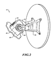
- FIGURE 2 illustrates an approach to calibrating a dual-axis radar-scanning assembly according to an embodiment of the invention
- FIGURE 3 illustrates a radar system according to another embodiment of the present invention
- FIGURE 4 shows a flowchart of an exemplary process performed by the system shown in FIGURE 3 ;
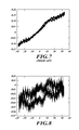
- FIGURES 5-8 illustrate the effect of the calibration procedure of an embodiment of the present invention on a radar system and of the prior art.
- a lesser precision sensor is "characterized" with a higher precision sensor
- the resultant data is stored onboard the radar system (e.g., in a database) and the stored data is smoothed by a smoothing function.
- the smoothing function improves system performance.
- Sensor construction and assembly in a higher-level system dictate the level of precision that the sensor is capable of. These effects are typically repeatable throughout the scan region of the radar antenna. Where a repeatable error exists, a higher precision sensor is able to measure that error throughout the scan region and to store the data representing such error for later use.
- an encoder of a higher precision, is used to measure the error of the resolvers used in the antenna's positioner.
- the encoder measures error during calibration of the antenna's scanning assembly to provide data that can be used onboard the radar system to compensate for the error, so as to provide onboard a true orientation of the resolvers, as measured during calibration, in relation to the erroneous orientation reported onboard by the resolvers.
- An embodiment of the present invention includes a method of improving position-control accuracy of a weather-radar antenna control system through calibration and data smoothing.
- An embodiment of the present invention includes a calibration system, used to characterize the target system, and associated software components required to download and smooth calibration data that are stored in a table.
- the target system, calibration system, and software components provide a method of improving system performance by compensating for deterministic position feedback error introduced by, for example, structural elements and position feedback sensors.
- FIGURE 2 illustrated is an approach, according to an embodiment of the present invention, to calibrating a dual-axis radar-scanning assembly 15, similar to assembly 10 illustrated in FIGURE 1 , in which like elements are designated by like reference numerals.
- the approach illustrated in FIGURE 2 includes calibrating antenna-position detection associated with the assembly 15, which is to be part of a radar system 300 ( FIGURE 3 ).
- the first and second gimbals 30, 40 are configured to rotate through a respective range of angular positions.
- Angle sensors associated with the assembly 15, such as resolvers 320, 330 ( FIGURE 3 ), are configured to detect the angular positions of the first and second gimbals 30, 40.
- the illustrated approach includes mounting high-precision angle sensors, such as optical-encoder sensors 60, 70, to end portions of the first gimbal 30 and second gimbal 40, respectively.
- the encoder sensors 60, 70 are configured to detect respective angular positions of the first and second gimbals 30, 40.
- the optical encoder sensors 60, 70 and associated components employed in an embodiment of the present invention may include, or be similar in functionality to, the sensor system having model number L-9517-9155-02A produced by RENISHAW ® .
- a sensor-ring portion of the encoder sensors 60, 70 is mounted onto respective ones of the axes of the end portions of first and second gimbals 30, 40.
- each of the first and second gimbals 30, 40 is rotated through a predetermined set of angular positions.
- first data sets are generated by the resolvers 320, 330 that characterize the detected angular position of the first and second gimbals 30, 40 at each angular position through which they are rotated.
- second data sets are generated by the encoder sensors 60, 70 that characterize the detected angular position of the first and second gimbals 30, 40 at each angular position through which they are rotated.
- first and second data sets are provided to a processing device (not shown) that is configured to determine a third data set characterizing errors in the angular-position measurements provided by the resolvers 320, 330 as determined from the measurements provided by the encoder sensors 60, 70.
- these errors may be characterized as the differences, between the first data set and second data set, in detected angular position at each angular position through which the first and second gimbals 30, 40 are rotated.
- the third data set is subsequently stored in a memory device, such as a database 340 ( FIGURE 3 ) onboard an aircraft or other vehicle in which the assembly 15 will be deployed.
- the radar system 300 includes the scanning assembly 15 illustrated in FIGURE 2 , not including the encoder sensors 60, 70.
- the system 300 includes an antenna element 310 mounted to the first and second gimbals 30, 40, the database 340, and a processing element 350.
- the database 340 includes the third data set characterizing errors in the angular-position measurements provided by the resolvers 320, 330 as determined from the measurements provided by the encoder sensors 60, 70.
- the processing element 350 receives from the resolvers 320, 330 detected angular positions of the first and second gimbals 30, 40, see block 382. Then, the processing element 350 applies a smoothing function to the third data set, see block 386. Next, the processing element 350 determines corrected, and more accurate, angular positions of the first and second gimbals 30, 40 using the results of the smoothing function, see block 388.
- error-compensated determinations are then provided by the processing element 350 to weather-monitoring avionics/electronics (not shown), or the like, aboard the aircraft or other vehicle in which the illustrated system 300 is implemented.
- the corrected angular position is used for the reported position or is used in the antenna drive command.
- the smoothing operation is performed on demand (i.e., at runtime).
- a command position signal is received at the processor.
- the processor then performs a smoothing operation on only the nearest values that are stored in the calibration table, based on the command position signal.
- the antenna is moved, based on the smoothed nearest values and the command position signal.
- An exemplary smoothing operation/function is polynomial curve fitting of the n nearest neighbors.
- a linear interpolation function is used to smooth two consecutive calibration table values using a line.
- Other smoothing functions may be used.
- FIGURES 5-8 illustrate the effect of the herein-described calibration procedure of an embodiment of the present invention on a radar system.
- FIGURES 5 and 6 show the azimuth-axis effect and FIGURES 7 and 8 show the elevation-axis effect. The openings are due to latencies in the reporting path and the speed of the antenna commanded.
- the error before optical calibration is ⁇ 0.3°; as shown in FIGURE 6 , after optical calibration (zero-point cal + optical encoder protocol) the azimuth error is reduced to ⁇ 0.07°.
- the elevation error is similarly affected: as can be seen from FIGURE 7 , before high-resolution calibration, the error is ⁇ 0.17°; as shown in FIGURE 8 , after high-resolution calibration, the error is ⁇ 0.06°.
Landscapes
- Engineering & Computer Science (AREA)
- Radar, Positioning & Navigation (AREA)
- Remote Sensing (AREA)
- Physics & Mathematics (AREA)
- Computer Networks & Wireless Communication (AREA)
- General Physics & Mathematics (AREA)
- Aviation & Aerospace Engineering (AREA)
- Electromagnetism (AREA)
- Radar Systems Or Details Thereof (AREA)
Applications Claiming Priority (1)
| Application Number | Priority Date | Filing Date | Title |
|---|---|---|---|
| US13/486,727 US8816901B2 (en) | 2012-06-01 | 2012-06-01 | Calibration to improve weather radar positioning determination |
Publications (2)
| Publication Number | Publication Date |
|---|---|
| EP2669701A1 true EP2669701A1 (de) | 2013-12-04 |
| EP2669701B1 EP2669701B1 (de) | 2016-11-23 |
Family
ID=48227065
Family Applications (1)
| Application Number | Title | Priority Date | Filing Date |
|---|---|---|---|
| EP13166711.5A Active EP2669701B1 (de) | 2012-06-01 | 2013-05-06 | Kalibrierung zur Verbesserung der Positionierungsbestimmung eines Wetterradars |
Country Status (2)
| Country | Link |
|---|---|
| US (1) | US8816901B2 (de) |
| EP (1) | EP2669701B1 (de) |
Cited By (1)
| Publication number | Priority date | Publication date | Assignee | Title |
|---|---|---|---|---|
| US20220301194A1 (en) * | 2017-05-25 | 2022-09-22 | SZ DJI Technology Co., Ltd. | Tracking method and device |
Families Citing this family (4)
| Publication number | Priority date | Publication date | Assignee | Title |
|---|---|---|---|---|
| US9243931B2 (en) * | 2012-11-28 | 2016-01-26 | Drs Sustainment Systems, Inc. | AZ/EL gimbal housing characterization |
| FR3002320B1 (fr) * | 2013-02-20 | 2016-05-20 | Airbus Operations Sas | Sonde de mesure angulaire a bord d'un aeronef et aeronef mettant en oeuvre au moins une telle sonde |
| WO2018191973A1 (zh) * | 2017-04-21 | 2018-10-25 | 深圳市大疆创新科技有限公司 | 一种用于与无人机通信的天线组件及无人机系统 |
| CN111044982B (zh) * | 2019-12-23 | 2021-09-28 | 广东纳睿雷达科技股份有限公司 | 一种雷达方位定位的方法 |
Citations (2)
| Publication number | Priority date | Publication date | Assignee | Title |
|---|---|---|---|---|
| DE10233155A1 (de) | 2002-07-22 | 2004-02-12 | Abb Patent Gmbh | Verfahren zur Korrektur systematischer Geometriefehler in einem Drehwinkelmessgerät |
| EP2230488A1 (de) | 2009-03-17 | 2010-09-22 | Honeywell International Inc. | Kalibrierung zur Verbesserung der Positionierungsbestimmung eines Wetterradars |
Family Cites Families (18)
| Publication number | Priority date | Publication date | Assignee | Title |
|---|---|---|---|---|
| US3984837A (en) * | 1975-03-31 | 1976-10-05 | The United States Of America As Represented By The Secretary Of The Navy | Rotatable and tiltable radome with independent scan and tilt antenna |
| US4536685A (en) * | 1982-03-03 | 1985-08-20 | Raytheon Company | Control for gimballed monopulse antenna arrangement |
| USH104H (en) * | 1985-06-03 | 1986-08-05 | The United States Of America As Represented By The Secretary Of The Army | Digital resolver compensation technique |
| US5196774A (en) * | 1991-07-22 | 1993-03-23 | The United States Of America As Represented By The Secretary Of The Air Force | Digital servo system |
| US5203220A (en) * | 1992-05-26 | 1993-04-20 | Gec-Marconi Electronic Systems Corp. | Optical tracking and stabilizing system with a gimbal mounted mirror for establishing a line of sight |
| US5557285A (en) * | 1994-01-24 | 1996-09-17 | Hughes Electronics | Gimbal control system |
| JPH08195614A (ja) * | 1994-11-16 | 1996-07-30 | Japan Radio Co Ltd | 追尾型アレイアンテナ装置 |
| US6268822B1 (en) * | 1999-12-07 | 2001-07-31 | Alenia Marconi Systems Inc. | Dual-frequency millimeter wave and laser radiation receiver |
| US6588699B2 (en) | 2001-04-03 | 2003-07-08 | Raytheon Company | Radar-guided missile programmable digital predetection signal processor |
| US6615117B2 (en) * | 2001-11-13 | 2003-09-02 | The Boeing Company | Attitude determination system and method with outer-loop gyro scale-factor non-linearity calibration |
| US6816112B1 (en) * | 2003-05-30 | 2004-11-09 | Lockheed Martin Corporation | Hybrid RF/optical acquisition and tracking system and method |
| US7199749B2 (en) | 2003-12-12 | 2007-04-03 | Georgia Tech Research Corporation | Radar detection device employing a scanning antenna system |
| US7154110B2 (en) | 2004-09-30 | 2006-12-26 | Xerox Corporation | Systems and methods for improving calibration of a linear array sensor |
| US7561968B2 (en) * | 2004-10-13 | 2009-07-14 | The Boeing Company | Scale factor calibration and compensation for angular position resolver |
| US7095376B1 (en) * | 2004-11-30 | 2006-08-22 | L3 Communications Corporation | System and method for pointing and control of an antenna |
| US7409292B2 (en) * | 2006-05-26 | 2008-08-05 | Honeywell International Inc. | Method and system for degimbalization of vehicle navigation data |
| US20100245196A1 (en) * | 2009-03-25 | 2010-09-30 | Eyal Miron | Antenna positioning system |
| US8586901B2 (en) * | 2010-08-26 | 2013-11-19 | Raytheon Company | Method for compensating for boresight error in missiles with composite radomes and guidance section with boresight error compensation |
-
2012
- 2012-06-01 US US13/486,727 patent/US8816901B2/en active Active
-
2013
- 2013-05-06 EP EP13166711.5A patent/EP2669701B1/de active Active
Patent Citations (2)
| Publication number | Priority date | Publication date | Assignee | Title |
|---|---|---|---|---|
| DE10233155A1 (de) | 2002-07-22 | 2004-02-12 | Abb Patent Gmbh | Verfahren zur Korrektur systematischer Geometriefehler in einem Drehwinkelmessgerät |
| EP2230488A1 (de) | 2009-03-17 | 2010-09-22 | Honeywell International Inc. | Kalibrierung zur Verbesserung der Positionierungsbestimmung eines Wetterradars |
Cited By (2)
| Publication number | Priority date | Publication date | Assignee | Title |
|---|---|---|---|---|
| US20220301194A1 (en) * | 2017-05-25 | 2022-09-22 | SZ DJI Technology Co., Ltd. | Tracking method and device |
| US11776139B2 (en) * | 2017-05-25 | 2023-10-03 | SZ DJI Technology Co., Ltd. | Tracking method and device |
Also Published As
| Publication number | Publication date |
|---|---|
| US8816901B2 (en) | 2014-08-26 |
| EP2669701B1 (de) | 2016-11-23 |
| US20130321197A1 (en) | 2013-12-05 |
Similar Documents
| Publication | Publication Date | Title |
|---|---|---|
| US8077080B2 (en) | Calibration to improve weather radar positioning determination | |
| JP2580832B2 (ja) | 移動体搭載アンテナ制御装置 | |
| US7797981B2 (en) | Position measuring device | |
| EP2669701B1 (de) | Kalibrierung zur Verbesserung der Positionierungsbestimmung eines Wetterradars | |
| US7724188B2 (en) | Gimbal system angle compensation | |
| US7421792B2 (en) | Apparatus and method of calibrating azimuth of mobile device | |
| US12146733B2 (en) | Measuring device and method of operating a measuring device | |
| CN113567963B (zh) | 一种对激光雷达测量误差进行精密检测的方法 | |
| US10031206B1 (en) | Calibration method of sensor of a satellite antenna | |
| KR20060132713A (ko) | 공간 내 물체의 위치를 측정하는 방법 | |
| JP2019100898A (ja) | 測量装置及びトータルステーションと2次元レーザスキャナとの組立て方法 | |
| KR101046915B1 (ko) | 레이돔에 의한 시선각 오차 보정 결과의 점검 | |
| US20150033567A1 (en) | System and method for determining angular differences on a potentially moving object | |
| CN113640589A (zh) | 基于辐射信号监测的偏心测量补偿系统、方法及介质 | |
| CN114688996B (zh) | 一种转台回转精度角度的测量方法 | |
| CN112946606B (zh) | 激光雷达的标定方法、装置、设备、系统及存储介质 | |
| CN118379361A (zh) | 基于视觉实现针对五轴激光切割机进行摆轴参数校验处理的方法、装置、处理器及存储介质 | |
| CN112578327B (zh) | 球面扫描测试系统的校准方法、设备及存储介质 | |
| CN112710340B (zh) | 用于校准车辆传感器的方法和设备 | |
| KR101197597B1 (ko) | 비정렬 오차 보정 방법 | |
| US11512983B2 (en) | Encoder and encoder control method | |
| US10732213B2 (en) | Method for measuring beam steering characteristics and measurement system | |
| KR101771469B1 (ko) | 위성 지향 안테나의 센서 보정 방법 | |
| CN107966701B (zh) | 一种雷达倾角测量方法及装置 | |
| KR101263745B1 (ko) | 전자광학장비에 장착된 회전형 각검출기의 위치출력오차 추정방법 |
Legal Events
| Date | Code | Title | Description |
|---|---|---|---|
| PUAI | Public reference made under article 153(3) epc to a published international application that has entered the european phase |
Free format text: ORIGINAL CODE: 0009012 |
|
| 17P | Request for examination filed |
Effective date: 20130506 |
|
| AK | Designated contracting states |
Kind code of ref document: A1 Designated state(s): AL AT BE BG CH CY CZ DE DK EE ES FI FR GB GR HR HU IE IS IT LI LT LU LV MC MK MT NL NO PL PT RO RS SE SI SK SM TR |
|
| AX | Request for extension of the european patent |
Extension state: BA ME |
|
| RAP1 | Party data changed (applicant data changed or rights of an application transferred) |
Owner name: HONEYWELL INTERNATIONAL INC. |
|
| GRAP | Despatch of communication of intention to grant a patent |
Free format text: ORIGINAL CODE: EPIDOSNIGR1 |
|
| INTG | Intention to grant announced |
Effective date: 20160707 |
|
| GRAS | Grant fee paid |
Free format text: ORIGINAL CODE: EPIDOSNIGR3 |
|
| GRAA | (expected) grant |
Free format text: ORIGINAL CODE: 0009210 |
|
| AK | Designated contracting states |
Kind code of ref document: B1 Designated state(s): AL AT BE BG CH CY CZ DE DK EE ES FI FR GB GR HR HU IE IS IT LI LT LU LV MC MK MT NL NO PL PT RO RS SE SI SK SM TR |
|
| REG | Reference to a national code |
Ref country code: GB Ref legal event code: FG4D |
|
| REG | Reference to a national code |
Ref country code: CH Ref legal event code: EP |
|
| REG | Reference to a national code |
Ref country code: IE Ref legal event code: FG4D |
|
| REG | Reference to a national code |
Ref country code: AT Ref legal event code: REF Ref document number: 848398 Country of ref document: AT Kind code of ref document: T Effective date: 20161215 |
|
| REG | Reference to a national code |
Ref country code: DE Ref legal event code: R096 Ref document number: 602013014312 Country of ref document: DE |
|
| REG | Reference to a national code |
Ref country code: NL Ref legal event code: FP |
|
| PG25 | Lapsed in a contracting state [announced via postgrant information from national office to epo] |
Ref country code: LV Free format text: LAPSE BECAUSE OF FAILURE TO SUBMIT A TRANSLATION OF THE DESCRIPTION OR TO PAY THE FEE WITHIN THE PRESCRIBED TIME-LIMIT Effective date: 20161123 |
|
| REG | Reference to a national code |
Ref country code: LT Ref legal event code: MG4D |
|
| REG | Reference to a national code |
Ref country code: AT Ref legal event code: MK05 Ref document number: 848398 Country of ref document: AT Kind code of ref document: T Effective date: 20161123 |
|
| REG | Reference to a national code |
Ref country code: FR Ref legal event code: PLFP Year of fee payment: 5 |
|
| PG25 | Lapsed in a contracting state [announced via postgrant information from national office to epo] |
Ref country code: NO Free format text: LAPSE BECAUSE OF FAILURE TO SUBMIT A TRANSLATION OF THE DESCRIPTION OR TO PAY THE FEE WITHIN THE PRESCRIBED TIME-LIMIT Effective date: 20170223 Ref country code: LT Free format text: LAPSE BECAUSE OF FAILURE TO SUBMIT A TRANSLATION OF THE DESCRIPTION OR TO PAY THE FEE WITHIN THE PRESCRIBED TIME-LIMIT Effective date: 20161123 Ref country code: GR Free format text: LAPSE BECAUSE OF FAILURE TO SUBMIT A TRANSLATION OF THE DESCRIPTION OR TO PAY THE FEE WITHIN THE PRESCRIBED TIME-LIMIT Effective date: 20170224 Ref country code: SE Free format text: LAPSE BECAUSE OF FAILURE TO SUBMIT A TRANSLATION OF THE DESCRIPTION OR TO PAY THE FEE WITHIN THE PRESCRIBED TIME-LIMIT Effective date: 20161123 |
|
| PG25 | Lapsed in a contracting state [announced via postgrant information from national office to epo] |
Ref country code: AT Free format text: LAPSE BECAUSE OF FAILURE TO SUBMIT A TRANSLATION OF THE DESCRIPTION OR TO PAY THE FEE WITHIN THE PRESCRIBED TIME-LIMIT Effective date: 20161123 Ref country code: PL Free format text: LAPSE BECAUSE OF FAILURE TO SUBMIT A TRANSLATION OF THE DESCRIPTION OR TO PAY THE FEE WITHIN THE PRESCRIBED TIME-LIMIT Effective date: 20161123 Ref country code: PT Free format text: LAPSE BECAUSE OF FAILURE TO SUBMIT A TRANSLATION OF THE DESCRIPTION OR TO PAY THE FEE WITHIN THE PRESCRIBED TIME-LIMIT Effective date: 20170323 Ref country code: HR Free format text: LAPSE BECAUSE OF FAILURE TO SUBMIT A TRANSLATION OF THE DESCRIPTION OR TO PAY THE FEE WITHIN THE PRESCRIBED TIME-LIMIT Effective date: 20161123 Ref country code: FI Free format text: LAPSE BECAUSE OF FAILURE TO SUBMIT A TRANSLATION OF THE DESCRIPTION OR TO PAY THE FEE WITHIN THE PRESCRIBED TIME-LIMIT Effective date: 20161123 Ref country code: ES Free format text: LAPSE BECAUSE OF FAILURE TO SUBMIT A TRANSLATION OF THE DESCRIPTION OR TO PAY THE FEE WITHIN THE PRESCRIBED TIME-LIMIT Effective date: 20161123 Ref country code: RS Free format text: LAPSE BECAUSE OF FAILURE TO SUBMIT A TRANSLATION OF THE DESCRIPTION OR TO PAY THE FEE WITHIN THE PRESCRIBED TIME-LIMIT Effective date: 20161123 |
|
| PG25 | Lapsed in a contracting state [announced via postgrant information from national office to epo] |
Ref country code: RO Free format text: LAPSE BECAUSE OF FAILURE TO SUBMIT A TRANSLATION OF THE DESCRIPTION OR TO PAY THE FEE WITHIN THE PRESCRIBED TIME-LIMIT Effective date: 20161123 Ref country code: DK Free format text: LAPSE BECAUSE OF FAILURE TO SUBMIT A TRANSLATION OF THE DESCRIPTION OR TO PAY THE FEE WITHIN THE PRESCRIBED TIME-LIMIT Effective date: 20161123 Ref country code: CZ Free format text: LAPSE BECAUSE OF FAILURE TO SUBMIT A TRANSLATION OF THE DESCRIPTION OR TO PAY THE FEE WITHIN THE PRESCRIBED TIME-LIMIT Effective date: 20161123 Ref country code: EE Free format text: LAPSE BECAUSE OF FAILURE TO SUBMIT A TRANSLATION OF THE DESCRIPTION OR TO PAY THE FEE WITHIN THE PRESCRIBED TIME-LIMIT Effective date: 20161123 Ref country code: SK Free format text: LAPSE BECAUSE OF FAILURE TO SUBMIT A TRANSLATION OF THE DESCRIPTION OR TO PAY THE FEE WITHIN THE PRESCRIBED TIME-LIMIT Effective date: 20161123 |
|
| REG | Reference to a national code |
Ref country code: DE Ref legal event code: R097 Ref document number: 602013014312 Country of ref document: DE |
|
| PG25 | Lapsed in a contracting state [announced via postgrant information from national office to epo] |
Ref country code: SM Free format text: LAPSE BECAUSE OF FAILURE TO SUBMIT A TRANSLATION OF THE DESCRIPTION OR TO PAY THE FEE WITHIN THE PRESCRIBED TIME-LIMIT Effective date: 20161123 Ref country code: LU Free format text: LAPSE BECAUSE OF NON-PAYMENT OF DUE FEES Effective date: 20170531 Ref country code: BE Free format text: LAPSE BECAUSE OF FAILURE TO SUBMIT A TRANSLATION OF THE DESCRIPTION OR TO PAY THE FEE WITHIN THE PRESCRIBED TIME-LIMIT Effective date: 20161123 Ref country code: BG Free format text: LAPSE BECAUSE OF FAILURE TO SUBMIT A TRANSLATION OF THE DESCRIPTION OR TO PAY THE FEE WITHIN THE PRESCRIBED TIME-LIMIT Effective date: 20170223 |
|
| PLBE | No opposition filed within time limit |
Free format text: ORIGINAL CODE: 0009261 |
|
| STAA | Information on the status of an ep patent application or granted ep patent |
Free format text: STATUS: NO OPPOSITION FILED WITHIN TIME LIMIT |
|
| 26N | No opposition filed |
Effective date: 20170824 |
|
| PG25 | Lapsed in a contracting state [announced via postgrant information from national office to epo] |
Ref country code: SI Free format text: LAPSE BECAUSE OF FAILURE TO SUBMIT A TRANSLATION OF THE DESCRIPTION OR TO PAY THE FEE WITHIN THE PRESCRIBED TIME-LIMIT Effective date: 20161123 |
|
| REG | Reference to a national code |
Ref country code: CH Ref legal event code: PL |
|
| REG | Reference to a national code |
Ref country code: NL Ref legal event code: MM Effective date: 20170601 |
|
| PG25 | Lapsed in a contracting state [announced via postgrant information from national office to epo] |
Ref country code: MC Free format text: LAPSE BECAUSE OF FAILURE TO SUBMIT A TRANSLATION OF THE DESCRIPTION OR TO PAY THE FEE WITHIN THE PRESCRIBED TIME-LIMIT Effective date: 20161123 |
|
| REG | Reference to a national code |
Ref country code: IE Ref legal event code: MM4A |
|
| PG25 | Lapsed in a contracting state [announced via postgrant information from national office to epo] |
Ref country code: CH Free format text: LAPSE BECAUSE OF NON-PAYMENT OF DUE FEES Effective date: 20170531 Ref country code: LI Free format text: LAPSE BECAUSE OF NON-PAYMENT OF DUE FEES Effective date: 20170531 |
|
| PG25 | Lapsed in a contracting state [announced via postgrant information from national office to epo] |
Ref country code: LU Free format text: LAPSE BECAUSE OF NON-PAYMENT OF DUE FEES Effective date: 20170506 Ref country code: NL Free format text: LAPSE BECAUSE OF NON-PAYMENT OF DUE FEES Effective date: 20170601 |
|
| PG25 | Lapsed in a contracting state [announced via postgrant information from national office to epo] |
Ref country code: IE Free format text: LAPSE BECAUSE OF NON-PAYMENT OF DUE FEES Effective date: 20170506 |
|
| REG | Reference to a national code |
Ref country code: FR Ref legal event code: PLFP Year of fee payment: 6 |
|
| PG25 | Lapsed in a contracting state [announced via postgrant information from national office to epo] |
Ref country code: IT Free format text: LAPSE BECAUSE OF NON-PAYMENT OF DUE FEES Effective date: 20170506 |
|
| PG25 | Lapsed in a contracting state [announced via postgrant information from national office to epo] |
Ref country code: MT Free format text: LAPSE BECAUSE OF NON-PAYMENT OF DUE FEES Effective date: 20170506 |
|
| PG25 | Lapsed in a contracting state [announced via postgrant information from national office to epo] |
Ref country code: HU Free format text: LAPSE BECAUSE OF FAILURE TO SUBMIT A TRANSLATION OF THE DESCRIPTION OR TO PAY THE FEE WITHIN THE PRESCRIBED TIME-LIMIT; INVALID AB INITIO Effective date: 20130506 |
|
| PG25 | Lapsed in a contracting state [announced via postgrant information from national office to epo] |
Ref country code: CY Free format text: LAPSE BECAUSE OF NON-PAYMENT OF DUE FEES Effective date: 20161123 |
|
| PG25 | Lapsed in a contracting state [announced via postgrant information from national office to epo] |
Ref country code: MK Free format text: LAPSE BECAUSE OF FAILURE TO SUBMIT A TRANSLATION OF THE DESCRIPTION OR TO PAY THE FEE WITHIN THE PRESCRIBED TIME-LIMIT Effective date: 20161123 |
|
| PG25 | Lapsed in a contracting state [announced via postgrant information from national office to epo] |
Ref country code: TR Free format text: LAPSE BECAUSE OF FAILURE TO SUBMIT A TRANSLATION OF THE DESCRIPTION OR TO PAY THE FEE WITHIN THE PRESCRIBED TIME-LIMIT Effective date: 20161123 |
|
| PG25 | Lapsed in a contracting state [announced via postgrant information from national office to epo] |
Ref country code: AL Free format text: LAPSE BECAUSE OF FAILURE TO SUBMIT A TRANSLATION OF THE DESCRIPTION OR TO PAY THE FEE WITHIN THE PRESCRIBED TIME-LIMIT Effective date: 20161123 Ref country code: IS Free format text: LAPSE BECAUSE OF FAILURE TO SUBMIT A TRANSLATION OF THE DESCRIPTION OR TO PAY THE FEE WITHIN THE PRESCRIBED TIME-LIMIT Effective date: 20170323 |
|
| PGFP | Annual fee paid to national office [announced via postgrant information from national office to epo] |
Ref country code: DE Payment date: 20200529 Year of fee payment: 8 |
|
| REG | Reference to a national code |
Ref country code: DE Ref legal event code: R119 Ref document number: 602013014312 Country of ref document: DE |
|
| PG25 | Lapsed in a contracting state [announced via postgrant information from national office to epo] |
Ref country code: DE Free format text: LAPSE BECAUSE OF NON-PAYMENT OF DUE FEES Effective date: 20211201 |
|
| PGFP | Annual fee paid to national office [announced via postgrant information from national office to epo] |
Ref country code: GB Payment date: 20220524 Year of fee payment: 10 |
|
| P01 | Opt-out of the competence of the unified patent court (upc) registered |
Effective date: 20230525 |
|
| GBPC | Gb: european patent ceased through non-payment of renewal fee |
Effective date: 20230506 |
|
| PG25 | Lapsed in a contracting state [announced via postgrant information from national office to epo] |
Ref country code: GB Free format text: LAPSE BECAUSE OF NON-PAYMENT OF DUE FEES Effective date: 20230506 |
|
| PGFP | Annual fee paid to national office [announced via postgrant information from national office to epo] |
Ref country code: FR Payment date: 20250526 Year of fee payment: 13 |