EP2232042B1 - Dispositif pour alimenter un moteur à combustion interne - Google Patents
Dispositif pour alimenter un moteur à combustion interne Download PDFInfo
- Publication number
- EP2232042B1 EP2232042B1 EP09700364.4A EP09700364A EP2232042B1 EP 2232042 B1 EP2232042 B1 EP 2232042B1 EP 09700364 A EP09700364 A EP 09700364A EP 2232042 B1 EP2232042 B1 EP 2232042B1
- Authority
- EP
- European Patent Office
- Prior art keywords
- duct
- perimetral band
- carburettor
- air filter
- axis
- Prior art date
- Legal status (The legal status is an assumption and is not a legal conclusion. Google has not performed a legal analysis and makes no representation as to the accuracy of the status listed.)
- Active
Links
Images



Classifications
-
- F—MECHANICAL ENGINEERING; LIGHTING; HEATING; WEAPONS; BLASTING
- F02—COMBUSTION ENGINES; HOT-GAS OR COMBUSTION-PRODUCT ENGINE PLANTS
- F02M—SUPPLYING COMBUSTION ENGINES IN GENERAL WITH COMBUSTIBLE MIXTURES OR CONSTITUENTS THEREOF
- F02M35/00—Combustion-air cleaners, air intakes, intake silencers, or induction systems specially adapted for, or arranged on, internal-combustion engines
- F02M35/10—Air intakes; Induction systems
- F02M35/1015—Air intakes; Induction systems characterised by the engine type
- F02M35/10196—Carburetted engines
-
- F—MECHANICAL ENGINEERING; LIGHTING; HEATING; WEAPONS; BLASTING
- F02—COMBUSTION ENGINES; HOT-GAS OR COMBUSTION-PRODUCT ENGINE PLANTS
- F02M—SUPPLYING COMBUSTION ENGINES IN GENERAL WITH COMBUSTIBLE MIXTURES OR CONSTITUENTS THEREOF
- F02M17/00—Carburettors having pertinent characteristics not provided for in, or of interest apart from, the apparatus of preceding main groups F02M1/00 - F02M15/00
- F02M17/34—Other carburettors combined or associated with other apparatus, e.g. air filters
-
- F—MECHANICAL ENGINEERING; LIGHTING; HEATING; WEAPONS; BLASTING
- F02—COMBUSTION ENGINES; HOT-GAS OR COMBUSTION-PRODUCT ENGINE PLANTS
- F02M—SUPPLYING COMBUSTION ENGINES IN GENERAL WITH COMBUSTIBLE MIXTURES OR CONSTITUENTS THEREOF
- F02M35/00—Combustion-air cleaners, air intakes, intake silencers, or induction systems specially adapted for, or arranged on, internal-combustion engines
- F02M35/10—Air intakes; Induction systems
- F02M35/10006—Air intakes; Induction systems characterised by the position of elements of the air intake system in direction of the air intake flow, i.e. between ambient air inlet and supply to the combustion chamber
- F02M35/10019—Means upstream of the fuel injection system, carburettor or plenum chamber
-
- F—MECHANICAL ENGINEERING; LIGHTING; HEATING; WEAPONS; BLASTING
- F02—COMBUSTION ENGINES; HOT-GAS OR COMBUSTION-PRODUCT ENGINE PLANTS
- F02M—SUPPLYING COMBUSTION ENGINES IN GENERAL WITH COMBUSTIBLE MIXTURES OR CONSTITUENTS THEREOF
- F02M35/00—Combustion-air cleaners, air intakes, intake silencers, or induction systems specially adapted for, or arranged on, internal-combustion engines
- F02M35/10—Air intakes; Induction systems
- F02M35/10242—Devices or means connected to or integrated into air intakes; Air intakes combined with other engine or vehicle parts
- F02M35/10275—Means to avoid a change in direction of incoming fluid, e.g. all intake ducts diverging from plenum chamber at acute angles; Check valves; Flame arrestors for backfire prevention
Definitions
- the present invention is a device for the supply of an air/fuel mixture to an internal combustion engine, in particular to a two stroke internal combustion engine, of a type destined for installation on portable work tools, for example chainsaws, bush-cutters, portable blowers, and similar.
- portable power tools are usually provided with a two stroke internal combustion engine, which, in addition to being of minor bulk and weight than a four stroke engine, are also constructionally simpler and consequently more economical.
- a two stroke internal combustion engine schematically comprises an external casing, which defines a lower engine compartment serving to contain the crank shaft and above at least a cylinder slidingly housing a piston coupled to the crank shaft.
- the piston defines a combustion chamber with the cylinder head of variable volume, separated by an airtight seal from the engine compartment.
- the engine compartment is provided with an inlet for the fresh air/fuel mixture, while the combustion chamber is provided with an exhaust outlet for the combustion gases.
- the engine compartment and combustion chamber are reciprocally connected through a transfer duct formed in the engine bodywork and comprising an inlet opening into the engine compartment and an outlet opening into the combustion chamber.
- the piston In proximity of the upper stroke limit, the piston closes the combustion chamber exhaust outlet and the transfer duct outlet, leaving open the inlet opening into the engine compartment; while in proximity to the lower stroke limit, the piston leaves open the combustion chamber exhaust outlet and the transfer duct outlet, closing the inlet opening into the engine compartment.
- the first operational stroke starts with the ignition of the air/fuel mixture in the combustion chamber when the piston it located at the upper limit position, and proceeds as the expansion of the gas pushes the piston towards the lower limit position, compressing the fresh air/fuel mixture contained in the engine compartment.
- the piston opens first the exhaust outlet, such that the combustion gas starts to exit the combustion chamber, and almost simultaneously the piston opens the transfer duct outlet such that the fresh mixture compressed in the engine compartment begins to flow into the combustion chamber until completely filling the chamber while the exhaust gas exits.
- the piston compresses the fresh air/fuel mixture contained in the combustion chamber and, before reaching the upper limit position, opens the inlet through which further fresh air/fuel mixture enters the engine compartment as a consequence of the internal depression generated therein.
- the spark plug When the piston reaches the upper limit position, the spark plug produces a spark which ignites the mixture in the combustion chamber and the cycle repeats.
- the fresh air/fuel mixture is supplied to the engine compartment through a device that comprises an air intake line, connected to the inlet and opening externally, along which are installed, in series, an air filter, and a carburettor wherein the filtered air arriving from the filter is mixed with the fuel before entering the engine.
- an anti-backflow element consisting substantially of an elbow joint in which the air/fluid mixture passing through the intake line is forced to make a marked change in direction.
- the drops of fuel striking the internal walls of the elbow joint can be fractioned by the impact into a plurality of smaller drops, sometimes sufficiently light to remain suspended in the airflow current and consequently to be carried by the pressure wave beyond the anti-backflow element towards the air filter.
- An aim of the present invention is to improve known devices for the supply of an air/fuel mixture to an internal combustion engine, and in particular a two stroke engine, such as to eliminate the back-flow of fuel towards the air filter.
- a further aim of the invention is to achieve the above mentioned aim by way of a simple, rational, and realtively inexpensive solution.
- a device for the supply of an internal combustion engine, typically two-stroke, comprising a carburettor and an air filter connected in series by at least a intake line, through which the air filtered by the filter is conveyed into the carburettor for mixing with the fuel, and an anti-backflow element located in series along the intake line between the carburettor and the air filter.
- the anti-backflow element exhibits an external casing comprising a perimetral band including at least a portion that is substantially circular in development and closed by two opposite side walls, such as to internally define at least a compartment in communication with the carburettor through an outlet duct, opening in the perimetral band and developing tangentially relative to the circularly developing portion, the compartment also in communication with the air filter through at least a first duct opening in one of the side walls.
- the first inlet duct of the anti-backflow element is preferably parallel to the axis of curvature of the circular portion of the perimetral band, such that the first inlet duct is substantially orthogonal to the plane along which the vortexual motion develops, reducing the opportunity for drops of fuel being projected internally and consequently reaching the air filter.
- the perimetral band preferably exhibits outward-curving walls in transverse cross-section, and is connected to the side walls of the cover, thereby forming a smooth continuous internal surface which facilitates the development of the vortexual motion and prevents accumulated fuel from remaining trapped.
- the first inlet duct of the anti-backflow element opens into the casing through an aperture positioned eccentrically relative to the axis of curvature of the circular portion of the perimetral band, such that a considerable portion of the perimetral band is laterally closed forming a beaker.
- the anti-backflow element can be fitted on the internal combustion engine, together with the other components of the supply device, such that when the engine is in the normal operating position, the circular portion of the perimetral band of the external cover is oriented with the axis of curvature horizontal, or orthogonal to the direction of the force of gravity, and the opening of the first duct is located at a height above the axis of curvature. In this position, the beaker is located at a lower position and consequently serves for the accumulation due to gravity of a considerable quantity of fuel, before onset of a risk of the fuel overflowing through the first inlet duct.
- the internal chamber of the anti-backflow element is also in communication with the air filter through a second access duct opening on the opposite side wall to that of the first access duct, both ducts being preferably equal in size and reciprocally aligned with each other.
- the perimetral band of the external cover consists of two portions of substantially circular development arranged symmetrically relative to a central axis of symmetry, such as to confer the perimetral band a substantially two-lobed profile.
- the circular portions are closed by the side walls of the external cover, such as to define two internal compartments, each compartment in communication with the carburettor through an outlet duct opening in the perimetral band and developing tangentially relative to the relevant circularly developing portion, and connected to the air filter through at least a first access duct opening in one of the side walls.
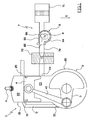
- Figure 1 schematically illustrates a typical two stroke internal combustion engine 1, of the type normally installed on portable power tools, such as for example chainsaws, bush-cutters, portable blowers, and similar.
- the engine 1 comprises an external cover, globally labelled as 2, defining a lower engine compartment 20 containing a crank shaft 3, and above at least a cylinder 21 slidingly housing a piston 4 connected to the crank shaft 3 by a con rod 40.
- the piston 4 defines a combustion chamber 22 with the cylinder head 21, separating, by an airtight seal, the combustion chamber 22 from an underlying compression chamber 23 defined inside the engine compartment 20.
- the combustion chamber 22 and the compression chamber 23 are both of variable volume, by effect of the sliding of the piston 4 inside the cylinder 21.
- the combustion chamber 22 and the compression chamber 23 are reciprocally connected through a transfer duct 5, formed in the body of the engine, which affords an inlet 50 opening into the compression chamber 23, and an outlet 51 opening into the combustion chamber 22.
- the compression chamber 23 also exhibits an inlet 24, located at a higher position relative to the inlet 50 of the transfer duct 5, through which the air/fuel mix, typically a petrol/oil mixture, is introduced inside the engine compartment 20.
- the air/fuel mix typically a petrol/oil mixture
- the combustion chamber 22 also exhibits an outlet 25, located at a height slightly higher relative to the outlet 51 of the transfer duct 5, through which combustion gas is released to the exterior.
- a spark plug 6 extends into the combustion chamber 22, fixed to the cylinder head 21 and serving to trigger the spark necessary for igniting the air/fuel mix.
- the piston 4 is shaped and scaled such that, when in proximity to the upper end of stroke position, where the volume of the combustion chamber 22 reaches minimum, the piston 4 closes the exhaust outlet 25 for combustion gases and the outlet 51 of the transfer duct 5, leaving open the inlet 24 which opens into the compression chamber 23. Conversely, when the piston 4 is in proximity to the lower end-of-stroke position, where the combustion chamber 22 reaches maximum volume, the piston 4 leaves open the exhaust outlet 25 for the combustion gasses and the outlet 51 of the transfer duct 5, closing the inlet 24. The inlet 50 of the transfer duct 5 always remains open.
- the inlet 24 is connected to a device for the supply of air/fuel mixture, labelled globally as 7, the device schematically comprising a intake line 70 connecting the inlet 24 with the external environment, along which, installed in series, are an air filter 71 and a carburettor 72 wherein the air from the filter 71 is mixed with the petrol/oil mixture before entering the engine 1.
- the air filter 71 and the carburettor 72 are of known type in the engine sector and consequently are not described herein in greater detail.
- the supply device 7 also comprises an anti-backflow element 8, which is also fitted in series on the intake line 70, between the air filter 71 and the carburettor 72.
- the intake line 70 here described schematically as a single duct should be considered in general as a system of one or more ducts serving to convey a flow of ambient air into the engine 1, transporting the air first through the filter 71, and then through the anti-backflow element 8, and finally through the carburettor 72.
- the anti-backflow element 8 comprises an external casing, referenced globally as 80, preferably realized as a single body in metal material by a process of moulding.
- the casing 80 comprises a perimetral band 81 of substantially circular transverse development (see figure 6 ), and two counterpositioned sides 82 and 83 serving to laterally close the perimetral band 81, such as to internally delimit a volute-shaped transit compartment 84 for the air/fuel mixture.
- the perimetral band 81 exhibits a rounded wall profile, illustrated in figure 7 , and is connected to the side walls 82 and 83, such that the internal surfaces of the casing 80 are generally smooth and continuous, and essentially without corners.
- the external casing 80 in the example illustrated, also comprises two inlet ducts to the transit compartment 84, and an outlet duct.
- the outlet duct 85 opens in the perimetral band 81, the axis of the outlet duct 85 lying substantially perpendicular to the axis of curvature A of the perimetral band 81.
- the duct 85 is of smaller diameter than the diameter of the perimetral band 81, and is delimited by a cylindrical side wall exhibiting a generatrix tangential to the perimetral band 81 (see figure 4 and 6 ). In this way, the duct 85 is aligned tangentially relative to the perimetral band 81, and serves to convey a flowing mass in a substantially tangential direction relative to the perimetral band 81.
- the free end of the duct 85 exhibits a flange 88 serving for the attachment of the anti-backflow element 8 to the carburettor 72 or in general to any other component of the intake line 70.
- a first inlet duct 86 opens in the side wall 82 of the external casing 80, extending axially for a relatively short distance.
- the first inlet duct 86 is of comparable diameter, although slightly inferior, to the diameter of the duct 85, the axis of the first inlet duct 86 developing substantially perpendicular to the axis of the duct 85, or substantially parallel to the axis of curvature A of the perimetral band 81.
- the first inlet duct 86 opens into the casing 80 through an opening that is eccentric in relation to the axis of curvature A of the perimetral band 81.
- a second inlet duct 87 opens on the opposite side wall 83 of the casing 80 identical to the first inlet duct 86, relative to which the second inlet duct 87 is perfectly aligned and counterpositioned.
- all the ducts 85-87 are eccentric relative to the axis of curvature A of the perimetral band 81, such that a wide portion of the perimetral band 81 is laterally closed forming a beaker.
- the anti-backflow element 8 is installed in the supply device 7, such that the transit compartment 84 defined by the casing 80 is in communication with the carburettor 72 through the duct 85, and such that the transit compartment 84 is in communication with the air filter 71 through the first and second inlets 86 and 87.
- the anti-backflow element 8 can be connected to the air filter 71 through a pair of ducts (not illustrated) connecting the air filter casing 71 with the first and second inlets 86 and 87 respectively; or the anti-backflow element 8 can be directly integrated into the air filter 71, such that the first and second inlets 86 and 87 open directly into the air filter casing, and only the duct 85 opens externally for connection to the carburettor 72.
- inlets 86 and 87 are described in the example, both serving to create communication between the anti-backflow element 8 and the air filter 71, in general it is sufficient that the anti-backflow element 8 is provided with at least one of these inlets.
- the anti-backflow element 8 is assembled with the other components of the supply device 7 and mounted on the engine 1, such that when the engine 1 is in its normal operating position, the anti-backflow element 8 is oriented with the axis of curvature A of the perimetral band 81 substantially horizontal, this being at right angles to the direction of the force of gravity (indicated with the arrow G), and the openings of ducts 85, 86, and 87 are in a raised position relative to the axis of curvature A.
- the beaker portion of the casing 80 is facing downwards, defining the bottom of the transit compartment 84.
- the normal operating position of the engine 1 is the position assumed by the engine during normal use of the power tool to which it is associated. If for example the engine 1 is installed on a mower or on a motor hoe, the normal operating position is the position of the engine 1 when the mower or motor hoe is advancing over the ground. If the engine 1 is installed on a portable blower, a chainsaw, or a bush cutter, the normal operating position is the position of the engine 1 when the tool is manoeuvred by the user.
- the fluid air/fuel mixture in the intake line 70 is accelerated towards the engine 1 and sucked into the compression chamber 23 inside the engine compartment 20. For this reason, when during the subsequent down stroke the piston 4 closes the inlet 24, the fluid mixture previously accelerated is blocked by the piston 4 (see figure 2 ) and, as a consequence of inertia, generates a reverse pressure wave and a inverse flow of the air/fuel mixture down the intake line 70 from the engine 1 towards the air filter 71.
- the inverse flow of air/fuel mixture passes through the carburettor 72 and enters the anti-backflow element 8 through the duct 85, where the tangential flow is directed against the perimetral band of circular development 81 of the outer casing 80.
- the vortexual motion of the air/fuel mixture inside casing 80 tends to project the drops of fuel radially against the internal surfaces of the perimetral) band 81, thereby separating the drops of fuel from the air and causing the fuel drops to accumulate by gravity on the bottom of the transit compartment 84.
- the installation position of the anti-backflow element 8 on the engine 1 is such that the base of the transit compartment 84 is normally defined by the beaker shaped portion of the casing 80, while the ducts 85-87 are located at a raised height relative to the axis of curvature A of the perimetral band 81.
- Fuel that accumulates inside the anti-backflow element 8 is transported into the engine during the subsequent intake phase.
- the specific shape of the anti-backflow element 8 causes the air passing through the casing 80 from the filter 71 towards the carburettor 72 to acquire the fuel accumulated in the transit compartment 84 and carry the fuel with it towards the engine 1. It is important to note that this elimination of accumulated fuel is encouraged by the continuous smooth internal surfaces of the casing 80, thereby not hindering the free flow of fuel and not affording corners in which fuel might remain trapped.
- Any excessive accumulations of fuel in the anti-backflow element 8 can also be released through a suitable valve (not illustrated) associated to the external casing 80.
- the inlets 86 and 87 are oriented parallel to the axis of curvature A of the perimetral band 81, the inlets 86 and 87 are substantially orthogonal to the plane along which the vortexual motion develops, reducing the probability that drops of fuel might be projected into the inlets 86 and 87 thereby reaching the air filter 71.
- the inverse flow of air/fuel mixture passes in front of the first and second ducts 86 and 87 before being deviated by the perimetral band 81, this being when the kinetic energy of the fuel drops contained in the air/fuel mixture is still high and the drops tend to continue in a rectilinear direction, parallel to the axis of duct 85.
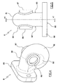
- FIGS 8 to 10 illustrate an anti-backflow element 8 in an alternative embodiment of the invention.
- the anti-backflow element 8 comprises an external casing 80 formed in a single body of metal material, the perimetral band thereof exhibiting two portions of circular development, respectively 81A and 81 B, arranged symmetrically relative to the central axis of symmetry, conferring the perimetral band a generally two-lobed profile.
- the two-lobed profile perimetral band is closed by side walls 82 and 83, thereby internally delimiting two spiral shaped compartments, 84A and 84B respectively, for the transit of the air/fuel mixture.
- the wall of the perimetral band is rounded and connects with the side walls 82 and 83, such that the internal surfaces of the casing 80 are substantially free of corners.
- the external casing 80 comprises two inlets 86A and 86B, both formed in the side wall 83 and individually creating communication between each of the respective internal compartments 84A and 84B and the air filter 71.
- the inlets 86A and 86B are arranged symmetrically relative to the central axis of symmetry of the perimetral band, exhibiting axes parallel to the axes of curvature of the relative circular portions 81A and 81 B.
- each inlet 86A and 86B opens into the casing 80 through an opening eccentric relative to the axis of curvature of the relative circular portion 81A and 81 B.
- the casing 80 further comprises a single central outlet 85 opening in the perimetral band and developing along the axis of symmetry, thereby creating communication between both the internal compartments 84A and 84B and the carburettor 72.
- the duct 85 exhibits a two-lobed transverse cross-section, comprising two extended portions 85A and 85B each facing a respective circular portion 81A and 81B of the perimetral band 81, and reciprocally connected by a central narrowing located on the axis of symmetry.
- each extended portion 85A and 85B serves to convey a portion of the air/fuel mixture in a direction substantially tangential to the relative circular portion 81A and 81 B of the perimetral band.
- the free end of the duct 85 exhibits a flange 88 serving for the fixing of the anti-backflow element 8 to the carburettor 72 or in general to any other component of the intake line 70.
- the anti-backflow element 8 of the second embodiment of the invention is installed in the supply device 7 in the same way as the first embodiment, wherein the transit chambers 84A and 84B are in communication with the carburettor 72 through the duct 85, and with the air filter 71 through the respective inlet ducts 86A and 86B, which can open directly into the filter casing.
- the anti-backflow element 8 is mounted such that when the engine 1 is in normal operating position, the axes of curvature of the circular portions 81A and 81 B of the perimetral band 81 are substantially horizontal.
- the air/fuel mixture passes through the carburettor 72 and enters the anti-backflow element 8 through the duct 85, where half of the flow is directed tangentially against the circular portion 81A and the other half tangentially against the circular portion 81 B.
- each transit compartment 84A and 84B of the anti-backflow element 8 a vortexual motion is established (indicated with the arrows in figure 10 ), the vortexual motion developing substantially along a perpendicular plane to the axis of curvature of the relative circular portions 81 A and 81 B.
- the two vortexual motions are counter rotating and tend to deviate the inverse flow of air/fuel mixture back towards the carburettor 72, preventing the drops of fuel contained in the air/fuel mixture from reaching the air filter 71.
- the drops of fuel that separate from the air collect on the internal surfaces of the perimetral band 81 and by gravity at the bottom of the lower transit compartment 84B, from where the drops of fuel are redirected back towards the engine 1 during the subsequent intake phase.
- An anti-backflow element of this second embodiment of the invention exhibits improved efficiency compared with the first embodiment described above, and reduced bulk.
Landscapes
- Engineering & Computer Science (AREA)
- Chemical & Material Sciences (AREA)
- Combustion & Propulsion (AREA)
- Mechanical Engineering (AREA)
- General Engineering & Computer Science (AREA)
- Filtering Of Dispersed Particles In Gases (AREA)
- Check Valves (AREA)
Claims (12)
- Dispositif d'alimentation d'un moteur à combustion interne (1) comprenant un carburateur (72) et un filtre à air (71) montés sur une ligne d'admission (70), de l'air filtré par un filtre à air (71) étant envoyé dans le carburateur (72) à travers ladite ligne d'admission (70), et un élément anti-reflux (8) agencé en série sur la ligne d'admission (70) entre le carburateur (72) et le filtre à air (71), dans lequel l'élément anti-reflux (8) présente un carter externe (80) comprenant une bande périmétrique (81) qui comporte au moins une partie à développement essentiellement circulaire fermée par deux parois latérales (82, 83), de manière à définir à l'intérieur au moins un compartiment (84) à géométrie invariable,
caractérisé en ce que l'élément anti-reflux (8) est en communication avec le carburateur (72) via un conduit (85) qui s'ouvre dans la bande périmétrique (81) et s'étend tangentiellement par rapport à la partie à développement circulaire ; le compartiment (84) étant également en communication avec le filtre à air (71) via au moins un premier conduit (86) qui s'ouvre dans une des deux parois latérales (82, 83). - Dispositif selon la revendication 1, caractérisé en ce que le premier conduit (86) est orienté parallèlement à l'axe de courbure (A) de ladite au moins une partie à développement essentiellement circulaire de la bande périmétrique (81) du carter externe (80).
- Dispositif selon la revendication 1, caractérisé en ce que le premier conduit (86) s'ouvre à l'intérieur du carter (80) dans une position excentrique par rapport à l'axe de courbure (A) de ladite au moins une partie à développement essentiellement circulaire de la bande périmétrique (81), définissant ainsi une spirale.
- Dispositif selon la revendication 1, caractérisé en ce que ledit au moins un compartiment défini par le carter externe (80) est en outre en communication avec le filtre à air (71) via un deuxième conduit (87) qui s'ouvre dans la paroi latérale (83) opposée à la paroi latérale (82) dans laquelle s'ouvre le premier conduit (86).
- Dispositif selon la revendication 4, caractérisé en ce que le deuxième conduit (87) est identique au premier conduit (86) et est aligné avec celui-ci.
- Dispositif selon la revendication 1, caractérisé en ce que la bande périmétrique du carter externe (80) comprend deux parties à développement essentiellement circulaire (81A, 81B), agencées symétriquement par rapport à un axe de symétrie central et fermées par les parois latérales (82, 83) de manière à définir deux compartiments internes (84A, 84B), chacun des compartiments internes (84A, 84B) étant en communication avec le carburateur (72) via un conduit (85) qui s'ouvre dans la bande périmétrique et s'étend tangentiellement par rapport à la partie à développement circulaire respective (81A, 81B), et les deux compartiments internes (84A, 84B) étant en communication avec le filtre à air (71) via au moins un conduit (86) qui s'ouvre dans une des parois latérales (83).
- Dispositif selon la revendication 6, caractérisé en ce que les compartiments internes (84A, 85B) sont en communication avec le carburateur (72) via un conduit unique (85) qui se développe le long de l'axe de symétrie de la bande périmétrique.
- Dispositif selon la revendication 7, caractérisé en ce que le conduit unique (85) présente une section transversale à deux lobes, comprenant deux parties étendues (85A, 85B) qui font individuellement face à une partie circulaire relative (81A, 81B) de la bande périmétrique, et connectées par un rétrécissement central sur un axe de symétrie correspondant.
- Dispositif selon la revendication 1, caractérisé en ce que la bande périmétrique (81) présente des parois arrondies en profil transversal et est connectée aux parois latérales (82, 83).
- Dispositif selon la revendication 1, caractérisé en ce que l'élément anti-reflux (8) est intégré dans le filtre à air (71), de telle sorte que ledit au moins un premier conduit (86) s'ouvre directement à l'intérieur du carter de filtre (71).
- Moteur à combustion interne caractérisé en ce qu'il comprend un dispositif d'alimentation (7) selon l'un quelconque des modes de réalisation des revendications précédentes.
- Moteur selon la revendication 11, caractérisé en ce que le dispositif d'alimentation est équipé de telle sorte que quand le moteur est en position de fonctionnement normale, l'élément anti-reflux (8) est aligné par rapport à l'axe de courbure (A) de ladite au moins une partie à développement essentiellement circulaire de la bande périmétrique essentiellement horizontale (81), et le premier conduit (86) est agencé en position relevée par rapport à l'axe de courbure (A).
Applications Claiming Priority (2)
| Application Number | Priority Date | Filing Date | Title |
|---|---|---|---|
| IT000003A ITRE20080003A1 (it) | 2008-01-10 | 2008-01-10 | '' dispositivo per l'alimentazione di un motore a combustione interna '' |
| PCT/EP2009/050111 WO2009087163A1 (fr) | 2008-01-10 | 2009-01-07 | Dispositif pour alimenter un moteur à combustion interne |
Publications (2)
| Publication Number | Publication Date |
|---|---|
| EP2232042A1 EP2232042A1 (fr) | 2010-09-29 |
| EP2232042B1 true EP2232042B1 (fr) | 2014-06-25 |
Family
ID=40290280
Family Applications (1)
| Application Number | Title | Priority Date | Filing Date |
|---|---|---|---|
| EP09700364.4A Active EP2232042B1 (fr) | 2008-01-10 | 2009-01-07 | Dispositif pour alimenter un moteur à combustion interne |
Country Status (6)
| Country | Link |
|---|---|
| US (1) | US8235021B2 (fr) |
| EP (1) | EP2232042B1 (fr) |
| CN (1) | CN101910602B (fr) |
| ES (1) | ES2493018T3 (fr) |
| IT (1) | ITRE20080003A1 (fr) |
| WO (1) | WO2009087163A1 (fr) |
Families Citing this family (3)
| Publication number | Priority date | Publication date | Assignee | Title |
|---|---|---|---|---|
| RU2511910C2 (ru) * | 2010-01-14 | 2014-04-10 | Хускварна Аб | Система впуска воздуха для двигателя внутреннего сгорания |
| JP6811269B2 (ja) * | 2019-02-25 | 2021-01-13 | 本田技研工業株式会社 | 内燃機関 |
| CN116838506B (zh) * | 2023-09-01 | 2023-11-07 | 山东赛诺凯特氢氨新能源有限公司 | 一种氨燃烧内燃机 |
Family Cites Families (15)
| Publication number | Priority date | Publication date | Assignee | Title |
|---|---|---|---|---|
| GB769041A (en) | 1954-05-06 | 1957-02-27 | Daimler Benz Ag | Improvements in induction pipes for internal combustion engines |
| US3955545A (en) * | 1974-06-25 | 1976-05-11 | Autotronic Controls Corporation | Post carburetor atomizer |
| JPS57181964A (en) * | 1981-05-02 | 1982-11-09 | Yamaha Motor Co Ltd | Suction device for internal combustion engine |
| US4592329A (en) * | 1981-10-19 | 1986-06-03 | Motortech, Inc. | Apparatus and operating method for an internal combustion engine |
| CN85105115B (zh) * | 1985-06-19 | 1988-03-16 | 廖智敏 | 反冲增压器 |
| US4759320A (en) * | 1986-08-06 | 1988-07-26 | Honda Giken Kogyo Kabushiki Kaisha | Intake device for an internal combustion engine |
| US4848281A (en) * | 1987-11-30 | 1989-07-18 | Mccord Ronald R | Pulse chamber and supercharging apparatus for internal combustion engines |
| US5375565A (en) * | 1993-12-16 | 1994-12-27 | Caterpillar Inc. | Flame arrestor and method of manufacture |
| JPH11229981A (ja) | 1998-02-13 | 1999-08-24 | Toyota Motor Corp | インテークマニホールド |
| US6167857B1 (en) * | 1998-08-07 | 2001-01-02 | Mccord Ronald R. | Timed tube induction system for improving the performance and efficiency of an internal combustion engine |
| AU2003292578A1 (en) * | 2002-12-20 | 2004-07-14 | Komatsu Zenoah Co. | Lead air control device of stratified scavenging two-cycle engine |
| US7107962B1 (en) * | 2004-10-27 | 2006-09-19 | Accessible Technologies, Inc. | Carburetor hat for forced induction system |
| JP2006241985A (ja) * | 2005-02-28 | 2006-09-14 | Toyota Motor Corp | 内燃機関の吸気装置 |
| US7478800B2 (en) * | 2005-03-04 | 2009-01-20 | Central Coast Patent Agency, Inc. | Anti-back-streaming carburetor valve |
| JP2007187122A (ja) * | 2006-01-16 | 2007-07-26 | Toyota Motor Corp | 内燃機関の吸気装置 |
-
2008
- 2008-01-10 IT IT000003A patent/ITRE20080003A1/it unknown
-
2009
- 2009-01-07 ES ES09700364.4T patent/ES2493018T3/es active Active
- 2009-01-07 US US12/812,522 patent/US8235021B2/en active Active
- 2009-01-07 EP EP09700364.4A patent/EP2232042B1/fr active Active
- 2009-01-07 WO PCT/EP2009/050111 patent/WO2009087163A1/fr not_active Ceased
- 2009-01-07 CN CN2009801016682A patent/CN101910602B/zh active Active
Also Published As
| Publication number | Publication date |
|---|---|
| US8235021B2 (en) | 2012-08-07 |
| ES2493018T3 (es) | 2014-09-11 |
| ITRE20080003A1 (it) | 2009-07-11 |
| CN101910602B (zh) | 2013-06-12 |
| US20100288220A1 (en) | 2010-11-18 |
| EP2232042A1 (fr) | 2010-09-29 |
| CN101910602A (zh) | 2010-12-08 |
| WO2009087163A1 (fr) | 2009-07-16 |
Similar Documents
| Publication | Publication Date | Title |
|---|---|---|
| US7090204B2 (en) | Carburetor arrangement | |
| US20210079821A1 (en) | Cylinder head oil separator for an internal combustion engine (flow-controlled oil separator) | |
| CN201581956U (zh) | 通用汽油机曲轴箱箱体的油气分离装置 | |
| CN100422542C (zh) | 吸气装置 | |
| EP2232042B1 (fr) | Dispositif pour alimenter un moteur à combustion interne | |
| US7228825B2 (en) | Two-stroke engine assembly | |
| CN109690047B (zh) | 二冲程内燃机 | |
| US3042013A (en) | Fuel supply means for engines | |
| US6601550B2 (en) | Method for operating a two-stroke engine | |
| US8746191B2 (en) | Two-stroke engine having an intake arrangement | |
| RU2005112005A (ru) | Двигатель с турбонаддувом с воспламенением от сжатия | |
| EP1009925B1 (fr) | Moteur a combustion interne a deux temps avec amelioration du systeme de circulation de carburant | |
| KR20240037942A (ko) | 내연기관용 강제흡기 시스템 및 방법 | |
| CN108343514A (zh) | 内燃机用流体流量调节装置及包含其的止回阀 | |
| KR200336348Y1 (ko) | 공기 압축기의 흡입휠터 구조 | |
| JPS5660884A (en) | Reciprocating gas compressor | |
| EP1207291B1 (fr) | Machine de jardinage à deux-temps à faible pollution | |
| JPH0756210B2 (ja) | 過給機付内燃機関に於ける吸気装置 | |
| JP2519965Y2 (ja) | 汎用エンジンの吸気装置 | |
| US2738918A (en) | Engine compressor unit | |
| RU2003121381A (ru) | Двухтактный двигатель внутреннего сгорания | |
| RU28381U1 (ru) | Двигатель | |
| RU2260129C2 (ru) | Двигатель внутреннего сгорания | |
| RU2260128C2 (ru) | Двигатель внутреннего сгорания | |
| JPH11182201A (ja) | 作動装置 |
Legal Events
| Date | Code | Title | Description |
|---|---|---|---|
| PUAI | Public reference made under article 153(3) epc to a published international application that has entered the european phase |
Free format text: ORIGINAL CODE: 0009012 |
|
| 17P | Request for examination filed |
Effective date: 20100622 |
|
| AK | Designated contracting states |
Kind code of ref document: A1 Designated state(s): AT BE BG CH CY CZ DE DK EE ES FI FR GB GR HR HU IE IS IT LI LT LU LV MC MK MT NL NO PL PT RO SE SI SK TR |
|
| AX | Request for extension of the european patent |
Extension state: AL BA RS |
|
| DAX | Request for extension of the european patent (deleted) | ||
| 17Q | First examination report despatched |
Effective date: 20120213 |
|
| GRAP | Despatch of communication of intention to grant a patent |
Free format text: ORIGINAL CODE: EPIDOSNIGR1 |
|
| INTG | Intention to grant announced |
Effective date: 20140203 |
|
| GRAS | Grant fee paid |
Free format text: ORIGINAL CODE: EPIDOSNIGR3 |
|
| GRAA | (expected) grant |
Free format text: ORIGINAL CODE: 0009210 |
|
| AK | Designated contracting states |
Kind code of ref document: B1 Designated state(s): AT BE BG CH CY CZ DE DK EE ES FI FR GB GR HR HU IE IS IT LI LT LU LV MC MK MT NL NO PL PT RO SE SI SK TR |
|
| REG | Reference to a national code |
Ref country code: GB Ref legal event code: FG4D |
|
| REG | Reference to a national code |
Ref country code: CH Ref legal event code: EP |
|
| REG | Reference to a national code |
Ref country code: AT Ref legal event code: REF Ref document number: 674875 Country of ref document: AT Kind code of ref document: T Effective date: 20140715 |
|
| REG | Reference to a national code |
Ref country code: IE Ref legal event code: FG4D |
|
| REG | Reference to a national code |
Ref country code: DE Ref legal event code: R096 Ref document number: 602009024880 Country of ref document: DE Effective date: 20140807 |
|
| REG | Reference to a national code |
Ref country code: ES Ref legal event code: FG2A Ref document number: 2493018 Country of ref document: ES Kind code of ref document: T3 Effective date: 20140911 |
|
| PG25 | Lapsed in a contracting state [announced via postgrant information from national office to epo] |
Ref country code: LT Free format text: LAPSE BECAUSE OF FAILURE TO SUBMIT A TRANSLATION OF THE DESCRIPTION OR TO PAY THE FEE WITHIN THE PRESCRIBED TIME-LIMIT Effective date: 20140625 Ref country code: NO Free format text: LAPSE BECAUSE OF FAILURE TO SUBMIT A TRANSLATION OF THE DESCRIPTION OR TO PAY THE FEE WITHIN THE PRESCRIBED TIME-LIMIT Effective date: 20140925 Ref country code: GR Free format text: LAPSE BECAUSE OF FAILURE TO SUBMIT A TRANSLATION OF THE DESCRIPTION OR TO PAY THE FEE WITHIN THE PRESCRIBED TIME-LIMIT Effective date: 20140926 Ref country code: FI Free format text: LAPSE BECAUSE OF FAILURE TO SUBMIT A TRANSLATION OF THE DESCRIPTION OR TO PAY THE FEE WITHIN THE PRESCRIBED TIME-LIMIT Effective date: 20140625 Ref country code: CY Free format text: LAPSE BECAUSE OF FAILURE TO SUBMIT A TRANSLATION OF THE DESCRIPTION OR TO PAY THE FEE WITHIN THE PRESCRIBED TIME-LIMIT Effective date: 20140625 |
|
| REG | Reference to a national code |
Ref country code: AT Ref legal event code: MK05 Ref document number: 674875 Country of ref document: AT Kind code of ref document: T Effective date: 20140625 |
|
| REG | Reference to a national code |
Ref country code: NL Ref legal event code: VDEP Effective date: 20140625 |
|
| REG | Reference to a national code |
Ref country code: LT Ref legal event code: MG4D |
|
| PG25 | Lapsed in a contracting state [announced via postgrant information from national office to epo] |
Ref country code: HR Free format text: LAPSE BECAUSE OF FAILURE TO SUBMIT A TRANSLATION OF THE DESCRIPTION OR TO PAY THE FEE WITHIN THE PRESCRIBED TIME-LIMIT Effective date: 20140625 Ref country code: LV Free format text: LAPSE BECAUSE OF FAILURE TO SUBMIT A TRANSLATION OF THE DESCRIPTION OR TO PAY THE FEE WITHIN THE PRESCRIBED TIME-LIMIT Effective date: 20140625 Ref country code: SE Free format text: LAPSE BECAUSE OF FAILURE TO SUBMIT A TRANSLATION OF THE DESCRIPTION OR TO PAY THE FEE WITHIN THE PRESCRIBED TIME-LIMIT Effective date: 20140625 |
|
| PG25 | Lapsed in a contracting state [announced via postgrant information from national office to epo] |
Ref country code: RO Free format text: LAPSE BECAUSE OF FAILURE TO SUBMIT A TRANSLATION OF THE DESCRIPTION OR TO PAY THE FEE WITHIN THE PRESCRIBED TIME-LIMIT Effective date: 20140625 Ref country code: EE Free format text: LAPSE BECAUSE OF FAILURE TO SUBMIT A TRANSLATION OF THE DESCRIPTION OR TO PAY THE FEE WITHIN THE PRESCRIBED TIME-LIMIT Effective date: 20140625 Ref country code: PT Free format text: LAPSE BECAUSE OF FAILURE TO SUBMIT A TRANSLATION OF THE DESCRIPTION OR TO PAY THE FEE WITHIN THE PRESCRIBED TIME-LIMIT Effective date: 20141027 Ref country code: SK Free format text: LAPSE BECAUSE OF FAILURE TO SUBMIT A TRANSLATION OF THE DESCRIPTION OR TO PAY THE FEE WITHIN THE PRESCRIBED TIME-LIMIT Effective date: 20140625 Ref country code: CZ Free format text: LAPSE BECAUSE OF FAILURE TO SUBMIT A TRANSLATION OF THE DESCRIPTION OR TO PAY THE FEE WITHIN THE PRESCRIBED TIME-LIMIT Effective date: 20140625 |
|
| PG25 | Lapsed in a contracting state [announced via postgrant information from national office to epo] |
Ref country code: AT Free format text: LAPSE BECAUSE OF FAILURE TO SUBMIT A TRANSLATION OF THE DESCRIPTION OR TO PAY THE FEE WITHIN THE PRESCRIBED TIME-LIMIT Effective date: 20140625 Ref country code: NL Free format text: LAPSE BECAUSE OF FAILURE TO SUBMIT A TRANSLATION OF THE DESCRIPTION OR TO PAY THE FEE WITHIN THE PRESCRIBED TIME-LIMIT Effective date: 20140625 Ref country code: IS Free format text: LAPSE BECAUSE OF FAILURE TO SUBMIT A TRANSLATION OF THE DESCRIPTION OR TO PAY THE FEE WITHIN THE PRESCRIBED TIME-LIMIT Effective date: 20141025 Ref country code: PL Free format text: LAPSE BECAUSE OF FAILURE TO SUBMIT A TRANSLATION OF THE DESCRIPTION OR TO PAY THE FEE WITHIN THE PRESCRIBED TIME-LIMIT Effective date: 20140625 |
|
| REG | Reference to a national code |
Ref country code: DE Ref legal event code: R097 Ref document number: 602009024880 Country of ref document: DE |
|
| PG25 | Lapsed in a contracting state [announced via postgrant information from national office to epo] |
Ref country code: DK Free format text: LAPSE BECAUSE OF FAILURE TO SUBMIT A TRANSLATION OF THE DESCRIPTION OR TO PAY THE FEE WITHIN THE PRESCRIBED TIME-LIMIT Effective date: 20140625 |
|
| PLBE | No opposition filed within time limit |
Free format text: ORIGINAL CODE: 0009261 |
|
| STAA | Information on the status of an ep patent application or granted ep patent |
Free format text: STATUS: NO OPPOSITION FILED WITHIN TIME LIMIT |
|
| 26N | No opposition filed |
Effective date: 20150326 |
|
| PG25 | Lapsed in a contracting state [announced via postgrant information from national office to epo] |
Ref country code: BE Free format text: LAPSE BECAUSE OF FAILURE TO SUBMIT A TRANSLATION OF THE DESCRIPTION OR TO PAY THE FEE WITHIN THE PRESCRIBED TIME-LIMIT Effective date: 20140625 |
|
| REG | Reference to a national code |
Ref country code: CH Ref legal event code: PL |
|
| PG25 | Lapsed in a contracting state [announced via postgrant information from national office to epo] |
Ref country code: LU Free format text: LAPSE BECAUSE OF FAILURE TO SUBMIT A TRANSLATION OF THE DESCRIPTION OR TO PAY THE FEE WITHIN THE PRESCRIBED TIME-LIMIT Effective date: 20150107 |
|
| PG25 | Lapsed in a contracting state [announced via postgrant information from national office to epo] |
Ref country code: MC Free format text: LAPSE BECAUSE OF FAILURE TO SUBMIT A TRANSLATION OF THE DESCRIPTION OR TO PAY THE FEE WITHIN THE PRESCRIBED TIME-LIMIT Effective date: 20140625 |
|
| PG25 | Lapsed in a contracting state [announced via postgrant information from national office to epo] |
Ref country code: LI Free format text: LAPSE BECAUSE OF NON-PAYMENT OF DUE FEES Effective date: 20150131 Ref country code: CH Free format text: LAPSE BECAUSE OF NON-PAYMENT OF DUE FEES Effective date: 20150131 |
|
| REG | Reference to a national code |
Ref country code: IE Ref legal event code: MM4A |
|
| PG25 | Lapsed in a contracting state [announced via postgrant information from national office to epo] |
Ref country code: SI Free format text: LAPSE BECAUSE OF FAILURE TO SUBMIT A TRANSLATION OF THE DESCRIPTION OR TO PAY THE FEE WITHIN THE PRESCRIBED TIME-LIMIT Effective date: 20140625 |
|
| REG | Reference to a national code |
Ref country code: FR Ref legal event code: PLFP Year of fee payment: 8 |
|
| PG25 | Lapsed in a contracting state [announced via postgrant information from national office to epo] |
Ref country code: IE Free format text: LAPSE BECAUSE OF NON-PAYMENT OF DUE FEES Effective date: 20150107 |
|
| PG25 | Lapsed in a contracting state [announced via postgrant information from national office to epo] |
Ref country code: MT Free format text: LAPSE BECAUSE OF FAILURE TO SUBMIT A TRANSLATION OF THE DESCRIPTION OR TO PAY THE FEE WITHIN THE PRESCRIBED TIME-LIMIT Effective date: 20140625 |
|
| REG | Reference to a national code |
Ref country code: FR Ref legal event code: PLFP Year of fee payment: 9 |
|
| PG25 | Lapsed in a contracting state [announced via postgrant information from national office to epo] |
Ref country code: BG Free format text: LAPSE BECAUSE OF FAILURE TO SUBMIT A TRANSLATION OF THE DESCRIPTION OR TO PAY THE FEE WITHIN THE PRESCRIBED TIME-LIMIT Effective date: 20140625 Ref country code: HU Free format text: LAPSE BECAUSE OF FAILURE TO SUBMIT A TRANSLATION OF THE DESCRIPTION OR TO PAY THE FEE WITHIN THE PRESCRIBED TIME-LIMIT; INVALID AB INITIO Effective date: 20090107 |
|
| REG | Reference to a national code |
Ref country code: FR Ref legal event code: PLFP Year of fee payment: 10 |
|
| PG25 | Lapsed in a contracting state [announced via postgrant information from national office to epo] |
Ref country code: MK Free format text: LAPSE BECAUSE OF FAILURE TO SUBMIT A TRANSLATION OF THE DESCRIPTION OR TO PAY THE FEE WITHIN THE PRESCRIBED TIME-LIMIT Effective date: 20140625 |
|
| P01 | Opt-out of the competence of the unified patent court (upc) registered |
Effective date: 20230605 |
|
| PGFP | Annual fee paid to national office [announced via postgrant information from national office to epo] |
Ref country code: GB Payment date: 20260127 Year of fee payment: 18 |
|
| PGFP | Annual fee paid to national office [announced via postgrant information from national office to epo] |
Ref country code: ES Payment date: 20260202 Year of fee payment: 18 |
|
| PGFP | Annual fee paid to national office [announced via postgrant information from national office to epo] |
Ref country code: DE Payment date: 20260128 Year of fee payment: 18 |
|
| PGFP | Annual fee paid to national office [announced via postgrant information from national office to epo] |
Ref country code: IT Payment date: 20251128 Year of fee payment: 18 |
|
| PGFP | Annual fee paid to national office [announced via postgrant information from national office to epo] |
Ref country code: FR Payment date: 20260126 Year of fee payment: 18 |
|
| PGFP | Annual fee paid to national office [announced via postgrant information from national office to epo] |
Ref country code: TR Payment date: 20260106 Year of fee payment: 18 |