EP2232093B1 - Bande de freinage d'un disque pour un disque de frein, disque d'un disque de frein, et procédé de fabrication de celui-ci - Google Patents
Bande de freinage d'un disque pour un disque de frein, disque d'un disque de frein, et procédé de fabrication de celui-ci Download PDFInfo
- Publication number
- EP2232093B1 EP2232093B1 EP07866801.9A EP07866801A EP2232093B1 EP 2232093 B1 EP2232093 B1 EP 2232093B1 EP 07866801 A EP07866801 A EP 07866801A EP 2232093 B1 EP2232093 B1 EP 2232093B1
- Authority
- EP
- European Patent Office
- Prior art keywords
- braking
- disc
- outer edge
- radially
- rotation axis
- Prior art date
- Legal status (The legal status is an assumption and is not a legal conclusion. Google has not performed a legal analysis and makes no representation as to the accuracy of the status listed.)
- Active
Links
Images


Classifications
-
- F—MECHANICAL ENGINEERING; LIGHTING; HEATING; WEAPONS; BLASTING
- F16—ENGINEERING ELEMENTS AND UNITS; GENERAL MEASURES FOR PRODUCING AND MAINTAINING EFFECTIVE FUNCTIONING OF MACHINES OR INSTALLATIONS; THERMAL INSULATION IN GENERAL
- F16D—COUPLINGS FOR TRANSMITTING ROTATION; CLUTCHES; BRAKES
- F16D65/00—Parts or details
- F16D65/02—Braking members; Mounting thereof
- F16D65/12—Discs; Drums for disc brakes
-
- F—MECHANICAL ENGINEERING; LIGHTING; HEATING; WEAPONS; BLASTING
- F16—ENGINEERING ELEMENTS AND UNITS; GENERAL MEASURES FOR PRODUCING AND MAINTAINING EFFECTIVE FUNCTIONING OF MACHINES OR INSTALLATIONS; THERMAL INSULATION IN GENERAL
- F16D—COUPLINGS FOR TRANSMITTING ROTATION; CLUTCHES; BRAKES
- F16D65/00—Parts or details
- F16D65/0006—Noise or vibration control
-
- F—MECHANICAL ENGINEERING; LIGHTING; HEATING; WEAPONS; BLASTING
- F16—ENGINEERING ELEMENTS AND UNITS; GENERAL MEASURES FOR PRODUCING AND MAINTAINING EFFECTIVE FUNCTIONING OF MACHINES OR INSTALLATIONS; THERMAL INSULATION IN GENERAL
- F16D—COUPLINGS FOR TRANSMITTING ROTATION; CLUTCHES; BRAKES
- F16D65/00—Parts or details
- F16D65/02—Braking members; Mounting thereof
- F16D2065/026—Braking members; Mounting thereof characterised by a particular outline shape of the braking member, e.g. footprint of friction lining
-
- F—MECHANICAL ENGINEERING; LIGHTING; HEATING; WEAPONS; BLASTING
- F16—ENGINEERING ELEMENTS AND UNITS; GENERAL MEASURES FOR PRODUCING AND MAINTAINING EFFECTIVE FUNCTIONING OF MACHINES OR INSTALLATIONS; THERMAL INSULATION IN GENERAL
- F16D—COUPLINGS FOR TRANSMITTING ROTATION; CLUTCHES; BRAKES
- F16D65/00—Parts or details
- F16D65/02—Braking members; Mounting thereof
- F16D2065/13—Parts or details of discs or drums
- F16D2065/1304—Structure
- F16D2065/1328—Structure internal cavities, e.g. cooling channels
-
- F—MECHANICAL ENGINEERING; LIGHTING; HEATING; WEAPONS; BLASTING
- F16—ENGINEERING ELEMENTS AND UNITS; GENERAL MEASURES FOR PRODUCING AND MAINTAINING EFFECTIVE FUNCTIONING OF MACHINES OR INSTALLATIONS; THERMAL INSULATION IN GENERAL
- F16D—COUPLINGS FOR TRANSMITTING ROTATION; CLUTCHES; BRAKES
- F16D69/00—Friction linings; Attachment thereof; Selection of coacting friction substances or surfaces
- F16D2069/004—Profiled friction surfaces, e.g. grooves, dimples
Definitions
- the present invention relates to a braking band of a disc for brake disc, as well as to a disc having a braking band of this type, and a method for manufacturing a braking band of this type.
- the present invention relates to braking bands that are capable to minimize and eliminate the high-frequency noise, or squeal, generated during the braking action that is exerted thereon by pads housed in a caliper arranged astride of said band.
- a braking band for motor vehicles is known from US-A-2002 040832 , having a band height varying along the circumferential extension thereof, thanks to the band outer and inner edges which are wavy and specular in relation to a circumference with band average height. Similar solutions are shown in US-A-6 131 707 , WO 99/50109 , EP-A-0 770 791 and DE 40 02 695 .
- a similar braking band is known from EP-A-1 596 088 , further provided with windows arranged in a quincunx pattern and axially passing therethrough, forming large apertures in the braking surfaces thereof.
- a constant-height braking surface is known from WO-A-2007 082574 , provided with band edges which are wavy and radially equally spaced along the circumferential extension thereof, so as to have a braking surface with a constant height.
- the problem underlying the present invention is to overcome the drawbacks of the to-date known prior art, by providing a braking band, and a brake disc comprising said band, which are able to obviate the drawbacks of the prior art.
- a further task of the present invention is also a method for achieving a braking band able to obviate the drawbacks of the prior art.
- radial recesses provided in the radially outer edges of the braking surfaces are present in the opposed braking surfaces and are angularly offset one to the other in a direction which is circumferential to the braking band, so as not to completely overlap each other in the axial direction.
- the at least one local decrease in the height of the at least one braking surface is achieved by means of a milling operation of its radially outer edge, for example, advantageously, through an axial feed of a hollow mill at least partially interfering with the braking band body in the proximity of the radially outer edge thereof.
- the dimensioning of the millings which locally reduce the braking surface height of the braking band depends on:
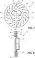
- a braking band 1 of a disc for brake disc comprises a body 2 having a pre-established rotation axis "a". Said body has a pre-established extension in the axial "a-a” and radial "r-r” directions in relation to said rotation axis ( Figure 1 ).
- said body 2 is restrained in the axial direction by a first braking surface 3 adapted to be rubbed by a first brake pad, supported by a caliper constrained to the vehicle and arranged astride of said band, in order to exert a braking action on the vehicle.
- a second braking surface 4 opposed to the first one in the axial direction, is adapted to be rubbed by a second brake pad, in order to exert a braking action on the vehicle.
- Said opposed braking surfaces 3, 4 axially define a braking volume 5 of said body.
- said first braking surface 3 comprises a first radially inner edge 6 which radially defines said surface on the rotation axis "a" side.
- Said first inner edge is inscribed by a first inner edge line 7 which is closed and lying on a circumference with radius "R1i" of a pre-established dimension.
- said first braking surface 3 comprises a first radially outer edge 8 which radially defines said surface on the opposed side to the rotation axis "a". Said first outer edge is circumscribed by a first outer edge line 9, which is, for example, closed.
- said second braking surface 4 comprises a second radially inner edge 10 which radially defines said surface on the rotation axis "a" side.
- Said second inner edge is inscribed by a second inner edge line 11 which is closed and lying on a circumference with radius "R2i" of a pre-established dimension.
- said second braking surface comprises a second radially outer edge 12, which radially defines said surface on the opposed side to the rotation axis "a"; said second outer edge being circumscribed by a second outer edge line 13, which is, for example, closed.
- said first and second outer edges are parts of a disc outer edge 14 which radially defines said disc on the opposed side to said rotation axis "a".
- At least one axial portion 15 of said disc outer edge 14 is circumscribed by a disc edge line 16, which is, for example, closed, and comprises at least one angular portion A, B, C, D, which is radially recessed towards the rotation axis "a" to form an edge outer recess 17 entering said braking volume 5 (for example, Figure 2 or Figure 17 ).
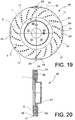
- said at least one axial portion 15 of said disc outer edge consists in at least two axial portions of disc outer edge 15, 18, each forming at least one outer edge recess 17, 19 ( Figures 17, 18 , 19, 20 ).
- said two axial portions of disc outer edge 15, 18 are axially spaced apart from each other, each forming at least one outer edge recess 17, 19.
- said at least one outer edge recess 17, 19 of said at least two outer edge axial portions 15, 18 are angularly spaced apart from each other "E" in the circumferential direction.
- said disc edge line 16 comprises circumference lengths centred on the disc body axis, and concavity towards the axis, and at least one circumference length 20 of opposed concavity, said edge line changing from convex to concave, and forming said at least one outer edge recess 17 and/or 19.
- said disc edge line 16 comprises circumference lengths that are centred on the disc body axis and concavity towards the axis, and at least one rectilinear length 21 lying on a straight line and forming said at least one outer edge recess.
- said straight line which said rectilinear length 21 lays on forms a chord on a circumference transversal to the rotation axis "a" and centred on said rotation axis.
- said disc outer edge 14 circumscribed by said disc edge line 16 comprises at least two outer edge recesses 17 entering said braking volume 5.
- said at least two recesses 17 are equally spaced from each other.
- said at least one outer recess 17, 19 is provided on said first or second lines of first or second outer edges 9, 13 of said first or second braking surfaces 3, 4.
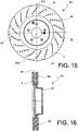
- said band 1 is a ventilated braking band and comprises two plates 30, 31, the gap between the plates defining a ventilation duct 22, said plates being connected by connection means 23 passing through said ventilation duct 22.
- said at least one outer recess 61 only involves said connection means 23 ( Figures 15 and 16 ), for example, said radial recesses are formed by levelling of the connection means, advantageously according to a chord at a circumference centred on the band rotation axis.
- connection means 23 are extended members or fins connecting the two plates in an essentially radial direction.
- connection means are pillar members or pins which locally connect the two plates 30, 31 to each other.
- said at least one outer recess 35, 36 only involves the radially outer edge 8, 12 of at least one plate 30 or 31 of the ventilated band ( Figures 17 to 20 ).
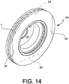
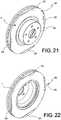
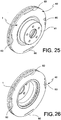
- said at least one axial portion 15, 18 of said disc outer edge 14 only partially involves the axial thickness of said disc body and, by being recessed in said braking volume 5 delimited by said braking surfaces 3, 4, it forms at least one groove 24 which at least partially splits at least one of said braking surfaces 3 and/or 4 ( Figures 13 , 14 , 21, 22 , 23, 24 , 25, 26 , 27, 28 ).
- said groove 24 comprises at least one rectilinear portion.
- said groove 60 is closed at the ends thereof, and is not joined to the radially outer edge 8 and/or 12 of the braking surface ( Figures 25 to 28 ).
- said radial outer recess is achieved with at least one groove drilled on at least one braking surface that is arranged on a chord of a circumference centred on the band surface axis.
- This at least one groove only very slightly reduces the braking surface extension, affecting the vibration modes of the braking band and eliminating the squeal generated during the braking action, but it does not considerably modify the surface which the braking pads act on.
- the braking band has at least one window or hole on at least one of the braking surfaces, for example blind or through windows or holes and, for example, a plurality of windows or holes.
- a braking band provided with opposed braking surfaces comprises radial recesses on the outer edges of said braking surfaces, and the radial recesses of a first braking surface are angularly offset in the circumferential direction in relation to the radial recesses of the opposed braking surface.
- a braking band provided with opposed braking surfaces comprises grooves lying on chords of circumferences centred on a band rotation axis and debouching on the outer edges of said braking surfaces, and the grooves of a first braking surface are angularly offset in the circumferential direction in relation to the grooves of the opposed braking surface.
- a brake disc 40 of brake disc comprises a braking band 1 according to any one of the previously-described embodiments.
- said disc 40 comprises a connecting bell 41 of said disc at a wheel hub of a vehicle suspension.
- said bell 41 is integral to said disc 40.
- a method for manufacturing a braking band 1 comprises the following steps:
- said radial recess is achieved by milling.
- said radial recess is achieved by levelling.
- At least two axial portions of disc outer edge 15, 18 are created, each forming at least one outer edge recess 17, 19.
- said two axial portions of disc outer edge 15, 18 are created axially spaced apart from each other, each forming at least one outer edge recess 17, 19.
- said at least one outer edge recess 17, 19 of said at least two outer edge axial portions are respectively created angularly spaced apart from each other E or E' in the circumferential direction.
Landscapes
- Engineering & Computer Science (AREA)
- General Engineering & Computer Science (AREA)
- Mechanical Engineering (AREA)
- Braking Arrangements (AREA)
Claims (12)
- Bande de freinage (1) d'un disque pour disque de frein comprenant :- un corps (2) présentant un axe de rotation (a) préétabli, ledit corps présentant une extension dans les directions axiale et radiale par rapport audit axe de rotation ;- ledit corps étant retenu dans la direction axiale par une première surface de freinage (3) adaptée pour être frottée par une plaquette de frein, afin d'exercer une action de freinage sur un véhicule ; et- une seconde surface de freinage (4), opposée à la première dans la direction axiale, et adaptée pour être frottée par une plaquette de frein, afin d'exercer une action de freinage sur un véhicule ;- lesdites surfaces de freinage (3, 4) opposées définissent axialement un volume de freinage (5) dudit corps ;- ladite première surface de freinage comprenant un premier bord radialement interne (6) qui définit radialement ladite surface sur le côté d'axe de rotation, ledit premier bord interne étant inscrit par une première ligne de bord interne (7) qui est fermée et reposant sur une circonférence avec un rayon (R1i) d'une dimension préétablie ;- ladite première surface de freinage comprenant un premier bord radialement externe (8) qui définit radialement ladite surface sur le côté opposé à l'axe de rotation, ledit premier bord externe étant circonscrit par une première ligne de bord externe (9) fermée ;- ladite seconde surface de freinage comprenant un second bord radialement interne (10) qui définit radialement ladite surface sur le côté d'axe de rotation, ledit second bord interne étant inscrit par une seconde ligne de bord interne (11) qui est fermée et reposant sur une circonférence avec un rayon (R2i) d'une dimension préétablie ;- ladite seconde surface de freinage comprenant un second bord radialement externe (12) qui définit radialement ladite surface sur le côté opposé à l'axe de rotation, ledit second bord externe étant circonscrit par une seconde ligne de bord externe (13) fermée,- lesdits premier et second bords externes étant des parties d'un bord externe de disque (14) qui définit radialement ledit disque sur le côté opposé audit axe de rotation ;- au moins une partie axiale (15) dudit bord externe de disque étant circonscrite par une ligne de bord de disque (16) fermée comprenant au moins une partie angulaire (A, B, C, D) qui est évidée radialement en direction de l'axe de rotation pour former un évidement externe de bord (17) entrant dans ledit volume de freinage ;- ladite au moins une partie axiale consiste en au moins deux parties axiales de bord externe de disque (15, 18), chacune formant au moins un évidement de bord externe (17, 19) ;dans laquelle- lesdites deux parties axiales de bord externe de disque (15, 18) sont espacées axialement l'une de l'autre ;
caractérisée par le fait que
les évidements de bord externe (17, 19) prévus dans les bords radialement externes des surfaces de freinage (3, 4) sont présents dans les surfaces de freinage (3, 4) opposées et sont décalés angulairement l'un de l'autre dans une direction circonférentielle par rapport à la bande de freinage, de manière à ne pas se chevaucher complètement mutuellement dans la direction axiale. - Bande de freinage selon la revendication 1, dans laquelle ledit au moins un évidement de bord externe (17, 19) desdites au moins deux parties axiales de bord externe sont au nombre de quatre et espacés angulairement les uns des autres de 90 degrés (E).
- Bande de freinage selon la revendication 1, dans laquelle ladite ligne de bord de disque (16) comprend des longueurs de circonférence qui sont centrées sur l'axe de corps de disque et une concavité en direction de l'axe, et au moins une longueur rectiligne (21) reposant sur une ligne droite et formant ledit au moins un évidement de bord externe et
dans laquelle ladite ligne droite, sur laquelle ladite longueur rectiligne (21) repose, forme une corde au niveau d'une circonférence transversale par rapport à l'axe de rotation (a) centrée sur ledit axe de rotation. - Bande de freinage selon une quelconque revendication précédente, dans laquelle ledit bord externe de disque circonscrit par ladite ligne de bord de disque (16) fermée comprend au moins deux évidements de bord externe entrant dans ledit volume de freinage.
- Bande de freinage selon la revendication 4, dans laquelle lesdits au moins deux évidements sont à équidistance l'un de l'autre.
- Bande de freinage selon une quelconque revendication précédente, dans laquelle ledit au moins un évidement externe est prévu sur lesdites première ou seconde lignes de premier ou second bords externes desdites première ou secondes surfaces de freinage.
- Bande de freinage selon une quelconque revendication précédente, dans laquelle ladite surface comprend deux plaques, l'espace entre les plaques définissant un conduit de ventilation (22), lesdites plaques étant raccordées par des moyens de raccordement (23) passant à travers ledit conduit de ventilation et dans laquelle ledit au moins un évidement externe implique uniquement le bord radialement externe d'au moins une plaque.
- Disque de freinage d'un disque de frein comprenant une bande de freinage selon une quelconque revendication précédente et comprenant une cloche de raccordement dudit disque à un moyeu de roue d'une suspension de véhicule, dans lequel ladite cloche fait partie intégrante dudit disque.
- Procédé pour fabriquer une bande de freinage, comprenant les étapes suivantes :- la fourniture d'un corps (2) présentant un axe de rotation (a) préétabli, ledit corps présentant une extension dans les directions axiale et radiale par rapport audit axe de rotation ;- la retenue dudit corps dans la direction axiale au moyen d'une première surface de freinage (3) adaptée pour être frottée par une plaquette de frein, afin d'exercer une action de freinage sur un véhicule et- la retenue dudit corps dans la direction axiale au moyen d'une seconde surface de freinage (4), opposée à la première dans la direction axiale, et adaptée pour être frottée par une plaquette de frein, afin d'exercer une action de freinage sur un véhicule ;- la retenue axiale d'un volume de freinage (5) dudit corps au moyen desdites surfaces de freinage (3, 4) opposées ;- la création d'un premier bord radialement interne (6) dans ladite première surface de freinage qui définit radialement ladite surface sur le côté d'axe de rotation, ledit premier bord interne étant inscrit par une première ligne de bord interne (7) qui est fermée et reposant sur une circonférence avec un rayon (R1i) d'une dimension préétablie ;- la création d'un premier bord radialement externe (8) dans ladite première surface de freinage qui définit radialement ladite surface sur le côté opposé à l'axe de rotation, ledit premier bord externe étant circonscrit par une première ligne de bord externe (9) fermée ;- la création d'un second bord radialement interne (10) dans ladite seconde surface de freinage qui définit radialement ladite surface sur le côté d'axe de rotation, ledit second bord interne étant inscrit par une seconde ligne de bord interne (11) qui est fermée et reposant sur une circonférence avec un rayon (R2i) d'une dimension préétablie ;- la création d'un second bord radialement externe (12) dans ladite seconde surface de freinage qui définit radialement ladite surface sur le côté opposé à l'axe de rotation, ledit second bord externe étant circonscrit par une seconde ligne de bord externe (13) fermée ;- la création d'un bord externe de disque (14) qui définit radialement ledit disque sur le côté opposé audit axe de rotation comprenant lesdits premier et second bords externes ;- la création, dans au moins une partie axiale (15) dudit bord externe de disque, circonscrit par une ligne de bord de disque (16) fermée, d'au moins une partie angulaire (A, B, C, D) qui est évidée radialement en direction de l'axe de rotation pour former un évidement externe de bord (17) entrant dans ledit volume de freinage ;- au moins deux parties axiales de bord externe de disque (15, 18) sont créées, chacune formant au moins un évidement de bord externe (17, 19) ;- lesdites deux parties axiales de bord externe de disque (15, 18) sont créées de manière espacée axialement l'une de l'autre ;caractérisé en ce qu'il comprend l'étape supplémentaire suivante :
les évidements de bord externe (17, 19) prévus dans les bords radialement externes des surfaces de freinage (3, 4) sont créés dans les surfaces de freinage (3, 4) opposées et sont créés de manière décalée angulairement l'un de l'autre dans une direction circonférentielle par rapport à la bande de freinage, de manière à ne pas se chevaucher complètement mutuellement dans la direction axiale. - Procédé selon la revendication 9, dans lequel ledit évidement radial est obtenu par fraisage.
- Procédé selon la revendication 9 ou 10, dans lequel ladite bande de freinage est ventilée dans au moins une des surfaces de freinage de celle-ci, par perçage d'au moins un trou borgne ou débouchant dans ladite au moins une surface de freinage.
- Procédé selon la revendication 9, dans lequel ledit évidement radial est obtenu par nivellement.
Priority Applications (1)
| Application Number | Priority Date | Filing Date | Title |
|---|---|---|---|
| HUE07866801A HUE057019T2 (hu) | 2007-12-13 | 2007-12-13 | Féktárcsához való tárcsa fékezõszalagja, féktárcsa tárcsája, valamint eljárás ennek elõállítására |
Applications Claiming Priority (1)
| Application Number | Priority Date | Filing Date | Title |
|---|---|---|---|
| PCT/IT2007/000869 WO2009075002A1 (fr) | 2007-12-13 | 2007-12-13 | Bande de freinage d'un disque pour un disque de frein, disque d'un disque de frein, et procédé de fabrication de celui-ci |
Publications (2)
| Publication Number | Publication Date |
|---|---|
| EP2232093A1 EP2232093A1 (fr) | 2010-09-29 |
| EP2232093B1 true EP2232093B1 (fr) | 2021-09-01 |
Family
ID=39718303
Family Applications (1)
| Application Number | Title | Priority Date | Filing Date |
|---|---|---|---|
| EP07866801.9A Active EP2232093B1 (fr) | 2007-12-13 | 2007-12-13 | Bande de freinage d'un disque pour un disque de frein, disque d'un disque de frein, et procédé de fabrication de celui-ci |
Country Status (3)
| Country | Link |
|---|---|
| EP (1) | EP2232093B1 (fr) |
| HU (1) | HUE057019T2 (fr) |
| WO (1) | WO2009075002A1 (fr) |
Families Citing this family (4)
| Publication number | Priority date | Publication date | Assignee | Title |
|---|---|---|---|---|
| US8146719B2 (en) * | 2008-04-25 | 2012-04-03 | GM Global Technology Operations LLC | Disk brake friction surfaces with tunable indent patterns for minimizing brake pad radial taper wear |
| US8287055B2 (en) | 2010-09-28 | 2012-10-16 | Robert Bosch Gmbh | Brake control of a vehicle based on driver behavior |
| FR2969727B1 (fr) * | 2010-12-24 | 2013-11-22 | Sncf | Dispositif de freinage a disque pour vehicule ferroviaire |
| DE102011115290A1 (de) * | 2011-09-29 | 2013-04-04 | Audi Ag | Bremsscheibe |
Family Cites Families (5)
| Publication number | Priority date | Publication date | Assignee | Title |
|---|---|---|---|---|
| DE4002695A1 (de) * | 1990-01-27 | 1991-08-01 | Porsche Ag | Bremsscheibe |
| JPH09126257A (ja) * | 1995-10-27 | 1997-05-13 | Shinko Electric Co Ltd | 摩擦式継手の摩擦板 |
| US6131707A (en) * | 1997-06-04 | 2000-10-17 | Kelsey-Hayes Company | Disc brake rotor and method for producing same |
| WO1999050109A1 (fr) * | 1998-03-31 | 1999-10-07 | Hayes Lemmerz International, Inc. | Partie roulante de frein a profile annulaire non circulaire |
| ITMI20050099A1 (it) * | 2005-01-25 | 2006-07-26 | Sunstar Logistic Singapore Pte | Disco frenante con profilo irregolare e freno comprendente tale disco |
-
2007
- 2007-12-13 HU HUE07866801A patent/HUE057019T2/hu unknown
- 2007-12-13 EP EP07866801.9A patent/EP2232093B1/fr active Active
- 2007-12-13 WO PCT/IT2007/000869 patent/WO2009075002A1/fr not_active Ceased
Also Published As
| Publication number | Publication date |
|---|---|
| WO2009075002A1 (fr) | 2009-06-18 |
| EP2232093A1 (fr) | 2010-09-29 |
| HUE057019T2 (hu) | 2022-04-28 |
Similar Documents
| Publication | Publication Date | Title |
|---|---|---|
| EP2025965B1 (fr) | Ensemble de disque de frein | |
| US8474580B2 (en) | Floating brake disc | |
| EP2232093B1 (fr) | Bande de freinage d'un disque pour un disque de frein, disque d'un disque de frein, et procédé de fabrication de celui-ci | |
| US10557510B2 (en) | Brake disc for a bicycle | |
| US9062730B2 (en) | Internally ventilated brake disk for disk brakes | |
| JP2011514862A (ja) | 機外側ハブバレル取付けロータ | |
| EP3163112A1 (fr) | Disque de frein | |
| US5474161A (en) | Rotor for a disc brake assembly and method of making same | |
| US7331433B2 (en) | Brake disc for automotive disc brake assembly | |
| EP3750720B1 (fr) | Roue de véhicule pour voitures | |
| US20180187730A1 (en) | Reinforced caliper housing | |
| JP6806744B2 (ja) | 車両用ホイール及び車両 | |
| EP3491264B1 (fr) | Disque de frein | |
| EP1382878B1 (fr) | Rotor de frein | |
| US10781877B2 (en) | Hub for mounting a brake disc to a vehicle axis | |
| EP1596088B1 (fr) | Disque de frein de vehicule | |
| EP3702636B1 (fr) | Ensemble rotor pour un système de frein à disque | |
| EP1760351B1 (fr) | Frein à disque et motocycle avec un tel frein à disque | |
| US20220080771A1 (en) | Non-pneumatic wheel with press fit hub | |
| JP7389050B2 (ja) | 軽量化ポケットを有するホイールディスクを備える製造加工された車両ホイール | |
| EP4574445A1 (fr) | Roue polygonale pour véhicules | |
| JP2010048302A (ja) | ディスクブレーキ | |
| WO2005075847A1 (fr) | Rotor de frein a disque et procede de production associe | |
| EP0641951B1 (fr) | Tambour de frein pour un frein de véhicule | |
| JP2010007844A (ja) | ディスクブレーキ |
Legal Events
| Date | Code | Title | Description |
|---|---|---|---|
| PUAI | Public reference made under article 153(3) epc to a published international application that has entered the european phase |
Free format text: ORIGINAL CODE: 0009012 |
|
| 17P | Request for examination filed |
Effective date: 20100712 |
|
| AK | Designated contracting states |
Kind code of ref document: A1 Designated state(s): AT BE BG CH CY CZ DE DK EE ES FI FR GB GR HU IE IS IT LI LT LU LV MC MT NL PL PT RO SE SI SK TR |
|
| AX | Request for extension of the european patent |
Extension state: AL BA HR MK RS |
|
| DAX | Request for extension of the european patent (deleted) | ||
| STAA | Information on the status of an ep patent application or granted ep patent |
Free format text: STATUS: EXAMINATION IS IN PROGRESS |
|
| 17Q | First examination report despatched |
Effective date: 20170802 |
|
| GRAP | Despatch of communication of intention to grant a patent |
Free format text: ORIGINAL CODE: EPIDOSNIGR1 |
|
| STAA | Information on the status of an ep patent application or granted ep patent |
Free format text: STATUS: GRANT OF PATENT IS INTENDED |
|
| INTG | Intention to grant announced |
Effective date: 20210412 |
|
| RAP3 | Party data changed (applicant data changed or rights of an application transferred) |
Owner name: BREMBO S.P.A. |
|
| GRAS | Grant fee paid |
Free format text: ORIGINAL CODE: EPIDOSNIGR3 |
|
| GRAA | (expected) grant |
Free format text: ORIGINAL CODE: 0009210 |
|
| STAA | Information on the status of an ep patent application or granted ep patent |
Free format text: STATUS: THE PATENT HAS BEEN GRANTED |
|
| RAP3 | Party data changed (applicant data changed or rights of an application transferred) |
Owner name: BREMBO S.P.A. |
|
| AK | Designated contracting states |
Kind code of ref document: B1 Designated state(s): AT BE BG CH CY CZ DE DK EE ES FI FR GB GR HU IE IS IT LI LT LU LV MC MT NL PL PT RO SE SI SK TR |
|
| REG | Reference to a national code |
Ref country code: GB Ref legal event code: FG4D |
|
| REG | Reference to a national code |
Ref country code: CH Ref legal event code: EP Ref country code: AT Ref legal event code: REF Ref document number: 1426552 Country of ref document: AT Kind code of ref document: T Effective date: 20210915 |
|
| REG | Reference to a national code |
Ref country code: DE Ref legal event code: R096 Ref document number: 602007061288 Country of ref document: DE |
|
| REG | Reference to a national code |
Ref country code: IE Ref legal event code: FG4D |
|
| REG | Reference to a national code |
Ref country code: LT Ref legal event code: MG9D |
|
| REG | Reference to a national code |
Ref country code: NL Ref legal event code: MP Effective date: 20210901 |
|
| PG25 | Lapsed in a contracting state [announced via postgrant information from national office to epo] |
Ref country code: SE Free format text: LAPSE BECAUSE OF FAILURE TO SUBMIT A TRANSLATION OF THE DESCRIPTION OR TO PAY THE FEE WITHIN THE PRESCRIBED TIME-LIMIT Effective date: 20210901 Ref country code: FI Free format text: LAPSE BECAUSE OF FAILURE TO SUBMIT A TRANSLATION OF THE DESCRIPTION OR TO PAY THE FEE WITHIN THE PRESCRIBED TIME-LIMIT Effective date: 20210901 Ref country code: ES Free format text: LAPSE BECAUSE OF FAILURE TO SUBMIT A TRANSLATION OF THE DESCRIPTION OR TO PAY THE FEE WITHIN THE PRESCRIBED TIME-LIMIT Effective date: 20210901 Ref country code: BG Free format text: LAPSE BECAUSE OF FAILURE TO SUBMIT A TRANSLATION OF THE DESCRIPTION OR TO PAY THE FEE WITHIN THE PRESCRIBED TIME-LIMIT Effective date: 20211201 Ref country code: LT Free format text: LAPSE BECAUSE OF FAILURE TO SUBMIT A TRANSLATION OF THE DESCRIPTION OR TO PAY THE FEE WITHIN THE PRESCRIBED TIME-LIMIT Effective date: 20210901 |
|
| REG | Reference to a national code |
Ref country code: AT Ref legal event code: MK05 Ref document number: 1426552 Country of ref document: AT Kind code of ref document: T Effective date: 20210901 |
|
| REG | Reference to a national code |
Ref country code: SK Ref legal event code: T3 Ref document number: E 38898 Country of ref document: SK |
|
| PG25 | Lapsed in a contracting state [announced via postgrant information from national office to epo] |
Ref country code: PL Free format text: LAPSE BECAUSE OF FAILURE TO SUBMIT A TRANSLATION OF THE DESCRIPTION OR TO PAY THE FEE WITHIN THE PRESCRIBED TIME-LIMIT Effective date: 20210901 Ref country code: LV Free format text: LAPSE BECAUSE OF FAILURE TO SUBMIT A TRANSLATION OF THE DESCRIPTION OR TO PAY THE FEE WITHIN THE PRESCRIBED TIME-LIMIT Effective date: 20210901 Ref country code: GR Free format text: LAPSE BECAUSE OF FAILURE TO SUBMIT A TRANSLATION OF THE DESCRIPTION OR TO PAY THE FEE WITHIN THE PRESCRIBED TIME-LIMIT Effective date: 20211202 |
|
| REG | Reference to a national code |
Ref country code: HU Ref legal event code: AG4A Ref document number: E057019 Country of ref document: HU |
|
| PG25 | Lapsed in a contracting state [announced via postgrant information from national office to epo] |
Ref country code: AT Free format text: LAPSE BECAUSE OF FAILURE TO SUBMIT A TRANSLATION OF THE DESCRIPTION OR TO PAY THE FEE WITHIN THE PRESCRIBED TIME-LIMIT Effective date: 20210901 |
|
| PG25 | Lapsed in a contracting state [announced via postgrant information from national office to epo] |
Ref country code: IS Free format text: LAPSE BECAUSE OF FAILURE TO SUBMIT A TRANSLATION OF THE DESCRIPTION OR TO PAY THE FEE WITHIN THE PRESCRIBED TIME-LIMIT Effective date: 20220101 Ref country code: RO Free format text: LAPSE BECAUSE OF FAILURE TO SUBMIT A TRANSLATION OF THE DESCRIPTION OR TO PAY THE FEE WITHIN THE PRESCRIBED TIME-LIMIT Effective date: 20210901 Ref country code: PT Free format text: LAPSE BECAUSE OF FAILURE TO SUBMIT A TRANSLATION OF THE DESCRIPTION OR TO PAY THE FEE WITHIN THE PRESCRIBED TIME-LIMIT Effective date: 20220103 Ref country code: NL Free format text: LAPSE BECAUSE OF FAILURE TO SUBMIT A TRANSLATION OF THE DESCRIPTION OR TO PAY THE FEE WITHIN THE PRESCRIBED TIME-LIMIT Effective date: 20210901 Ref country code: EE Free format text: LAPSE BECAUSE OF FAILURE TO SUBMIT A TRANSLATION OF THE DESCRIPTION OR TO PAY THE FEE WITHIN THE PRESCRIBED TIME-LIMIT Effective date: 20210901 Ref country code: CZ Free format text: LAPSE BECAUSE OF FAILURE TO SUBMIT A TRANSLATION OF THE DESCRIPTION OR TO PAY THE FEE WITHIN THE PRESCRIBED TIME-LIMIT Effective date: 20210901 |
|
| REG | Reference to a national code |
Ref country code: DE Ref legal event code: R097 Ref document number: 602007061288 Country of ref document: DE |
|
| PLBE | No opposition filed within time limit |
Free format text: ORIGINAL CODE: 0009261 |
|
| STAA | Information on the status of an ep patent application or granted ep patent |
Free format text: STATUS: NO OPPOSITION FILED WITHIN TIME LIMIT |
|
| PG25 | Lapsed in a contracting state [announced via postgrant information from national office to epo] |
Ref country code: MC Free format text: LAPSE BECAUSE OF FAILURE TO SUBMIT A TRANSLATION OF THE DESCRIPTION OR TO PAY THE FEE WITHIN THE PRESCRIBED TIME-LIMIT Effective date: 20210901 Ref country code: IT Free format text: LAPSE BECAUSE OF FAILURE TO SUBMIT A TRANSLATION OF THE DESCRIPTION OR TO PAY THE FEE WITHIN THE PRESCRIBED TIME-LIMIT Effective date: 20210901 Ref country code: DK Free format text: LAPSE BECAUSE OF FAILURE TO SUBMIT A TRANSLATION OF THE DESCRIPTION OR TO PAY THE FEE WITHIN THE PRESCRIBED TIME-LIMIT Effective date: 20210901 |
|
| REG | Reference to a national code |
Ref country code: CH Ref legal event code: PL |
|
| 26N | No opposition filed |
Effective date: 20220602 |
|
| PG25 | Lapsed in a contracting state [announced via postgrant information from national office to epo] |
Ref country code: SI Free format text: LAPSE BECAUSE OF FAILURE TO SUBMIT A TRANSLATION OF THE DESCRIPTION OR TO PAY THE FEE WITHIN THE PRESCRIBED TIME-LIMIT Effective date: 20210901 |
|
| REG | Reference to a national code |
Ref country code: BE Ref legal event code: MM Effective date: 20211231 |
|
| PG25 | Lapsed in a contracting state [announced via postgrant information from national office to epo] |
Ref country code: LU Free format text: LAPSE BECAUSE OF NON-PAYMENT OF DUE FEES Effective date: 20211213 Ref country code: IE Free format text: LAPSE BECAUSE OF NON-PAYMENT OF DUE FEES Effective date: 20211213 |
|
| PG25 | Lapsed in a contracting state [announced via postgrant information from national office to epo] |
Ref country code: BE Free format text: LAPSE BECAUSE OF NON-PAYMENT OF DUE FEES Effective date: 20211231 |
|
| PG25 | Lapsed in a contracting state [announced via postgrant information from national office to epo] |
Ref country code: LI Free format text: LAPSE BECAUSE OF NON-PAYMENT OF DUE FEES Effective date: 20211231 Ref country code: CH Free format text: LAPSE BECAUSE OF NON-PAYMENT OF DUE FEES Effective date: 20211231 |
|
| PG25 | Lapsed in a contracting state [announced via postgrant information from national office to epo] |
Ref country code: CY Free format text: LAPSE BECAUSE OF FAILURE TO SUBMIT A TRANSLATION OF THE DESCRIPTION OR TO PAY THE FEE WITHIN THE PRESCRIBED TIME-LIMIT Effective date: 20210901 |
|
| P01 | Opt-out of the competence of the unified patent court (upc) registered |
Effective date: 20230526 |
|
| PG25 | Lapsed in a contracting state [announced via postgrant information from national office to epo] |
Ref country code: TR Free format text: LAPSE BECAUSE OF FAILURE TO SUBMIT A TRANSLATION OF THE DESCRIPTION OR TO PAY THE FEE WITHIN THE PRESCRIBED TIME-LIMIT Effective date: 20210901 |
|
| PG25 | Lapsed in a contracting state [announced via postgrant information from national office to epo] |
Ref country code: MT Free format text: LAPSE BECAUSE OF FAILURE TO SUBMIT A TRANSLATION OF THE DESCRIPTION OR TO PAY THE FEE WITHIN THE PRESCRIBED TIME-LIMIT Effective date: 20210901 |
|
| PGFP | Annual fee paid to national office [announced via postgrant information from national office to epo] |
Ref country code: GB Payment date: 20251219 Year of fee payment: 19 |
|
| PGFP | Annual fee paid to national office [announced via postgrant information from national office to epo] |
Ref country code: HU Payment date: 20251223 Year of fee payment: 19 Ref country code: FR Payment date: 20251128 Year of fee payment: 19 |
|
| PGFP | Annual fee paid to national office [announced via postgrant information from national office to epo] |
Ref country code: SK Payment date: 20251210 Year of fee payment: 19 |
|
| PGFP | Annual fee paid to national office [announced via postgrant information from national office to epo] |
Ref country code: DE Payment date: 20251222 Year of fee payment: 19 |