EP2233178A1 - Übungsassistenzsystem - Google Patents
Übungsassistenzsystem Download PDFInfo
- Publication number
- EP2233178A1 EP2233178A1 EP08866122A EP08866122A EP2233178A1 EP 2233178 A1 EP2233178 A1 EP 2233178A1 EP 08866122 A EP08866122 A EP 08866122A EP 08866122 A EP08866122 A EP 08866122A EP 2233178 A1 EP2233178 A1 EP 2233178A1
- Authority
- EP
- European Patent Office
- Prior art keywords
- bearing member
- user
- load
- foot
- load applied
- Prior art date
- Legal status (The legal status is an assumption and is not a legal conclusion. Google has not performed a legal analysis and makes no representation as to the accuracy of the status listed.)
- Withdrawn
Links
- 210000003141 lower extremity Anatomy 0.000 claims abstract description 49
- 238000001514 detection method Methods 0.000 claims abstract description 38
- 210000002683 foot Anatomy 0.000 description 145
- 210000003205 muscle Anatomy 0.000 description 26
- 208000006820 Arthralgia Diseases 0.000 description 15
- 208000024765 knee pain Diseases 0.000 description 15
- 230000033001 locomotion Effects 0.000 description 15
- 208000007366 Genu Valgum Diseases 0.000 description 12
- 208000010300 Genu Varum Diseases 0.000 description 12
- 206010062061 Knee deformity Diseases 0.000 description 12
- 210000000988 bone and bone Anatomy 0.000 description 6
- 230000005540 biological transmission Effects 0.000 description 5
- 210000001217 buttock Anatomy 0.000 description 5
- 210000000544 articulatio talocruralis Anatomy 0.000 description 4
- 230000000694 effects Effects 0.000 description 4
- 238000004519 manufacturing process Methods 0.000 description 4
- 230000036544 posture Effects 0.000 description 4
- 230000000284 resting effect Effects 0.000 description 4
- 230000008878 coupling Effects 0.000 description 3
- 238000010168 coupling process Methods 0.000 description 3
- 238000005859 coupling reaction Methods 0.000 description 3
- 210000002414 leg Anatomy 0.000 description 3
- 208000003947 Knee Osteoarthritis Diseases 0.000 description 2
- 238000005452 bending Methods 0.000 description 2
- 230000033228 biological regulation Effects 0.000 description 2
- 230000037396 body weight Effects 0.000 description 2
- 210000001503 joint Anatomy 0.000 description 2
- 210000003127 knee Anatomy 0.000 description 2
- 210000000629 knee joint Anatomy 0.000 description 2
- 239000000463 material Substances 0.000 description 2
- 201000008482 osteoarthritis Diseases 0.000 description 2
- 230000011514 reflex Effects 0.000 description 2
- 238000005096 rolling process Methods 0.000 description 2
- 230000003213 activating effect Effects 0.000 description 1
- 230000003247 decreasing effect Effects 0.000 description 1
- 238000010586 diagram Methods 0.000 description 1
- 239000013013 elastic material Substances 0.000 description 1
- 210000004394 hip joint Anatomy 0.000 description 1
- 230000004118 muscle contraction Effects 0.000 description 1
- 230000010355 oscillation Effects 0.000 description 1
- 230000000149 penetrating effect Effects 0.000 description 1
- 230000002093 peripheral effect Effects 0.000 description 1
- 230000002265 prevention Effects 0.000 description 1
- 230000002035 prolonged effect Effects 0.000 description 1
- 239000004065 semiconductor Substances 0.000 description 1
- 238000010008 shearing Methods 0.000 description 1
- 238000004088 simulation Methods 0.000 description 1
- 230000002747 voluntary effect Effects 0.000 description 1
Images


Classifications
-
- A—HUMAN NECESSITIES
- A63—SPORTS; GAMES; AMUSEMENTS
- A63B—APPARATUS FOR PHYSICAL TRAINING, GYMNASTICS, SWIMMING, CLIMBING, OR FENCING; BALL GAMES; TRAINING EQUIPMENT
- A63B22/00—Exercising apparatus specially adapted for conditioning the cardio-vascular system, for training agility or co-ordination of movements
- A63B22/16—Platforms for rocking motion about a horizontal axis, e.g. axis through the middle of the platform; Balancing drums; Balancing boards or the like
-
- A—HUMAN NECESSITIES
- A61—MEDICAL OR VETERINARY SCIENCE; HYGIENE
- A61H—PHYSICAL THERAPY APPARATUS, e.g. DEVICES FOR LOCATING OR STIMULATING REFLEX POINTS IN THE BODY; ARTIFICIAL RESPIRATION; MASSAGE; BATHING DEVICES FOR SPECIAL THERAPEUTIC OR HYGIENIC PURPOSES OR SPECIFIC PARTS OF THE BODY
- A61H1/00—Apparatus for passive exercising; Vibrating apparatus; Chiropractic devices, e.g. body impacting devices, external devices for briefly extending or aligning unbroken bones
- A61H1/005—Moveable platforms, e.g. vibrating or oscillating platforms for standing, sitting, laying or leaning
-
- A—HUMAN NECESSITIES
- A61—MEDICAL OR VETERINARY SCIENCE; HYGIENE
- A61H—PHYSICAL THERAPY APPARATUS, e.g. DEVICES FOR LOCATING OR STIMULATING REFLEX POINTS IN THE BODY; ARTIFICIAL RESPIRATION; MASSAGE; BATHING DEVICES FOR SPECIAL THERAPEUTIC OR HYGIENIC PURPOSES OR SPECIFIC PARTS OF THE BODY
- A61H1/00—Apparatus for passive exercising; Vibrating apparatus; Chiropractic devices, e.g. body impacting devices, external devices for briefly extending or aligning unbroken bones
- A61H1/02—Stretching or bending or torsioning apparatus for exercising
- A61H1/0237—Stretching or bending or torsioning apparatus for exercising for the lower limbs
- A61H1/0266—Foot
-
- A—HUMAN NECESSITIES
- A63—SPORTS; GAMES; AMUSEMENTS
- A63B—APPARATUS FOR PHYSICAL TRAINING, GYMNASTICS, SWIMMING, CLIMBING, OR FENCING; BALL GAMES; TRAINING EQUIPMENT
- A63B21/00—Exercising apparatus for developing or strengthening the muscles or joints of the body by working against a counterforce, with or without measuring devices
- A63B21/00178—Exercising apparatus for developing or strengthening the muscles or joints of the body by working against a counterforce, with or without measuring devices for active exercising, the apparatus being also usable for passive exercising
-
- A—HUMAN NECESSITIES
- A63—SPORTS; GAMES; AMUSEMENTS
- A63B—APPARATUS FOR PHYSICAL TRAINING, GYMNASTICS, SWIMMING, CLIMBING, OR FENCING; BALL GAMES; TRAINING EQUIPMENT
- A63B21/00—Exercising apparatus for developing or strengthening the muscles or joints of the body by working against a counterforce, with or without measuring devices
- A63B21/40—Interfaces with the user related to strength training; Details thereof
- A63B21/4001—Arrangements for attaching the exercising apparatus to the user's body, e.g. belts, shoes or gloves specially adapted therefor
- A63B21/4011—Arrangements for attaching the exercising apparatus to the user's body, e.g. belts, shoes or gloves specially adapted therefor to the lower limbs
- A63B21/4015—Arrangements for attaching the exercising apparatus to the user's body, e.g. belts, shoes or gloves specially adapted therefor to the lower limbs to the foot
-
- A—HUMAN NECESSITIES
- A63—SPORTS; GAMES; AMUSEMENTS
- A63B—APPARATUS FOR PHYSICAL TRAINING, GYMNASTICS, SWIMMING, CLIMBING, OR FENCING; BALL GAMES; TRAINING EQUIPMENT
- A63B23/00—Exercising apparatus specially adapted for particular parts of the body
- A63B23/035—Exercising apparatus specially adapted for particular parts of the body for limbs, i.e. upper or lower limbs, e.g. simultaneously
- A63B23/04—Exercising apparatus specially adapted for particular parts of the body for limbs, i.e. upper or lower limbs, e.g. simultaneously for lower limbs
- A63B23/0405—Exercising apparatus specially adapted for particular parts of the body for limbs, i.e. upper or lower limbs, e.g. simultaneously for lower limbs involving a bending of the knee and hip joints simultaneously
-
- A—HUMAN NECESSITIES
- A63—SPORTS; GAMES; AMUSEMENTS
- A63B—APPARATUS FOR PHYSICAL TRAINING, GYMNASTICS, SWIMMING, CLIMBING, OR FENCING; BALL GAMES; TRAINING EQUIPMENT
- A63B24/00—Electric or electronic controls for exercising apparatus of preceding groups; Controlling or monitoring of exercises, sportive games, training or athletic performances
- A63B24/0087—Electric or electronic controls for exercising apparatus of groups A63B21/00 - A63B23/00, e.g. controlling load
-
- A—HUMAN NECESSITIES
- A61—MEDICAL OR VETERINARY SCIENCE; HYGIENE
- A61H—PHYSICAL THERAPY APPARATUS, e.g. DEVICES FOR LOCATING OR STIMULATING REFLEX POINTS IN THE BODY; ARTIFICIAL RESPIRATION; MASSAGE; BATHING DEVICES FOR SPECIAL THERAPEUTIC OR HYGIENIC PURPOSES OR SPECIFIC PARTS OF THE BODY
- A61H1/00—Apparatus for passive exercising; Vibrating apparatus; Chiropractic devices, e.g. body impacting devices, external devices for briefly extending or aligning unbroken bones
- A61H1/02—Stretching or bending or torsioning apparatus for exercising
- A61H1/0237—Stretching or bending or torsioning apparatus for exercising for the lower limbs
-
- A—HUMAN NECESSITIES
- A61—MEDICAL OR VETERINARY SCIENCE; HYGIENE
- A61H—PHYSICAL THERAPY APPARATUS, e.g. DEVICES FOR LOCATING OR STIMULATING REFLEX POINTS IN THE BODY; ARTIFICIAL RESPIRATION; MASSAGE; BATHING DEVICES FOR SPECIAL THERAPEUTIC OR HYGIENIC PURPOSES OR SPECIFIC PARTS OF THE BODY
- A61H2201/00—Characteristics of apparatus not provided for in the preceding codes
- A61H2201/12—Driving means
- A61H2201/1207—Driving means with electric or magnetic drive
- A61H2201/1215—Rotary drive
-
- A—HUMAN NECESSITIES
- A61—MEDICAL OR VETERINARY SCIENCE; HYGIENE
- A61H—PHYSICAL THERAPY APPARATUS, e.g. DEVICES FOR LOCATING OR STIMULATING REFLEX POINTS IN THE BODY; ARTIFICIAL RESPIRATION; MASSAGE; BATHING DEVICES FOR SPECIAL THERAPEUTIC OR HYGIENIC PURPOSES OR SPECIFIC PARTS OF THE BODY
- A61H2201/00—Characteristics of apparatus not provided for in the preceding codes
- A61H2201/14—Special force transmission means, i.e. between the driving means and the interface with the user
-
- A—HUMAN NECESSITIES
- A61—MEDICAL OR VETERINARY SCIENCE; HYGIENE
- A61H—PHYSICAL THERAPY APPARATUS, e.g. DEVICES FOR LOCATING OR STIMULATING REFLEX POINTS IN THE BODY; ARTIFICIAL RESPIRATION; MASSAGE; BATHING DEVICES FOR SPECIAL THERAPEUTIC OR HYGIENIC PURPOSES OR SPECIFIC PARTS OF THE BODY
- A61H2201/00—Characteristics of apparatus not provided for in the preceding codes
- A61H2201/16—Physical interface with patient
- A61H2201/1602—Physical interface with patient kind of interface, e.g. head rest, knee support or lumbar support
- A61H2201/1628—Pelvis
- A61H2201/1633—Seat
-
- A—HUMAN NECESSITIES
- A61—MEDICAL OR VETERINARY SCIENCE; HYGIENE
- A61H—PHYSICAL THERAPY APPARATUS, e.g. DEVICES FOR LOCATING OR STIMULATING REFLEX POINTS IN THE BODY; ARTIFICIAL RESPIRATION; MASSAGE; BATHING DEVICES FOR SPECIAL THERAPEUTIC OR HYGIENIC PURPOSES OR SPECIFIC PARTS OF THE BODY
- A61H2201/00—Characteristics of apparatus not provided for in the preceding codes
- A61H2201/16—Physical interface with patient
- A61H2201/1602—Physical interface with patient kind of interface, e.g. head rest, knee support or lumbar support
- A61H2201/1635—Hand or arm, e.g. handle
-
- A—HUMAN NECESSITIES
- A61—MEDICAL OR VETERINARY SCIENCE; HYGIENE
- A61H—PHYSICAL THERAPY APPARATUS, e.g. DEVICES FOR LOCATING OR STIMULATING REFLEX POINTS IN THE BODY; ARTIFICIAL RESPIRATION; MASSAGE; BATHING DEVICES FOR SPECIAL THERAPEUTIC OR HYGIENIC PURPOSES OR SPECIFIC PARTS OF THE BODY
- A61H2201/00—Characteristics of apparatus not provided for in the preceding codes
- A61H2201/16—Physical interface with patient
- A61H2201/1602—Physical interface with patient kind of interface, e.g. head rest, knee support or lumbar support
- A61H2201/164—Feet or leg, e.g. pedal
-
- A—HUMAN NECESSITIES
- A61—MEDICAL OR VETERINARY SCIENCE; HYGIENE
- A61H—PHYSICAL THERAPY APPARATUS, e.g. DEVICES FOR LOCATING OR STIMULATING REFLEX POINTS IN THE BODY; ARTIFICIAL RESPIRATION; MASSAGE; BATHING DEVICES FOR SPECIAL THERAPEUTIC OR HYGIENIC PURPOSES OR SPECIFIC PARTS OF THE BODY
- A61H2201/00—Characteristics of apparatus not provided for in the preceding codes
- A61H2201/16—Physical interface with patient
- A61H2201/1657—Movement of interface, i.e. force application means
- A61H2201/1664—Movement of interface, i.e. force application means linear
-
- A—HUMAN NECESSITIES
- A61—MEDICAL OR VETERINARY SCIENCE; HYGIENE
- A61H—PHYSICAL THERAPY APPARATUS, e.g. DEVICES FOR LOCATING OR STIMULATING REFLEX POINTS IN THE BODY; ARTIFICIAL RESPIRATION; MASSAGE; BATHING DEVICES FOR SPECIAL THERAPEUTIC OR HYGIENIC PURPOSES OR SPECIFIC PARTS OF THE BODY
- A61H2201/00—Characteristics of apparatus not provided for in the preceding codes
- A61H2201/16—Physical interface with patient
- A61H2201/1657—Movement of interface, i.e. force application means
- A61H2201/1676—Pivoting
-
- A—HUMAN NECESSITIES
- A61—MEDICAL OR VETERINARY SCIENCE; HYGIENE
- A61H—PHYSICAL THERAPY APPARATUS, e.g. DEVICES FOR LOCATING OR STIMULATING REFLEX POINTS IN THE BODY; ARTIFICIAL RESPIRATION; MASSAGE; BATHING DEVICES FOR SPECIAL THERAPEUTIC OR HYGIENIC PURPOSES OR SPECIFIC PARTS OF THE BODY
- A61H2201/00—Characteristics of apparatus not provided for in the preceding codes
- A61H2201/50—Control means thereof
- A61H2201/5002—Means for controlling a set of similar massage devices acting in sequence at different locations on a patient
-
- A—HUMAN NECESSITIES
- A61—MEDICAL OR VETERINARY SCIENCE; HYGIENE
- A61H—PHYSICAL THERAPY APPARATUS, e.g. DEVICES FOR LOCATING OR STIMULATING REFLEX POINTS IN THE BODY; ARTIFICIAL RESPIRATION; MASSAGE; BATHING DEVICES FOR SPECIAL THERAPEUTIC OR HYGIENIC PURPOSES OR SPECIFIC PARTS OF THE BODY
- A61H2201/00—Characteristics of apparatus not provided for in the preceding codes
- A61H2201/50—Control means thereof
- A61H2201/5007—Control means thereof computer controlled
-
- A—HUMAN NECESSITIES
- A61—MEDICAL OR VETERINARY SCIENCE; HYGIENE
- A61H—PHYSICAL THERAPY APPARATUS, e.g. DEVICES FOR LOCATING OR STIMULATING REFLEX POINTS IN THE BODY; ARTIFICIAL RESPIRATION; MASSAGE; BATHING DEVICES FOR SPECIAL THERAPEUTIC OR HYGIENIC PURPOSES OR SPECIFIC PARTS OF THE BODY
- A61H2201/00—Characteristics of apparatus not provided for in the preceding codes
- A61H2201/50—Control means thereof
- A61H2201/5058—Sensors or detectors
- A61H2201/5061—Force sensors
-
- A—HUMAN NECESSITIES
- A61—MEDICAL OR VETERINARY SCIENCE; HYGIENE
- A61H—PHYSICAL THERAPY APPARATUS, e.g. DEVICES FOR LOCATING OR STIMULATING REFLEX POINTS IN THE BODY; ARTIFICIAL RESPIRATION; MASSAGE; BATHING DEVICES FOR SPECIAL THERAPEUTIC OR HYGIENIC PURPOSES OR SPECIFIC PARTS OF THE BODY
- A61H2203/00—Additional characteristics concerning the patient
- A61H2203/04—Position of the patient
- A61H2203/0425—Sitting on the buttocks
-
- A—HUMAN NECESSITIES
- A63—SPORTS; GAMES; AMUSEMENTS
- A63B—APPARATUS FOR PHYSICAL TRAINING, GYMNASTICS, SWIMMING, CLIMBING, OR FENCING; BALL GAMES; TRAINING EQUIPMENT
- A63B2220/00—Measuring of physical parameters relating to sporting activity
- A63B2220/50—Force related parameters
- A63B2220/51—Force
-
- A—HUMAN NECESSITIES
- A63—SPORTS; GAMES; AMUSEMENTS
- A63B—APPARATUS FOR PHYSICAL TRAINING, GYMNASTICS, SWIMMING, CLIMBING, OR FENCING; BALL GAMES; TRAINING EQUIPMENT
- A63B69/00—Training appliances or apparatus for special sports
- A63B69/04—Training appliances or apparatus for special sports simulating the movement of horses
Definitions
- the present invention relates to an exercise assisting device which gives an exercise effect to a user without the user's voluntary (active) exercise.
- the exercise assisting devices are known to be classified into two types, one being configured to apply a force of bending joints of the user for stretching the muscles associated with the joints, and the other configured to apply a stimulus to a user's body to cause a nervous reflex by which associated muscles are forced to stretch.
- the exercise assisting devices are designed to require the user to take different postures depending upon the muscles to be stretched.
- One example of the exercise assisting devices is to simulate a walking by the user at a standing posture, as proposed in JP 2003-290386 A and JP10-55131 A .
- JP 2003-290386 A discloses a training device which includes a pair of steps bearing thereon left and right feet of the user, and is configured to interlock the reciprocating movements of the left and right steps for providing a skating simulation exercise to the user.
- the device is arranged to shift the user's weight along forward/rearward direction and also along lateral direction such that the user makes the use of one's nervous reflex to keep a balance with an effect of stretching the muscles.
- the steps are driven by a driving mechanism to move so that the user can enjoy the passive exercise simply by placing one's feet on the steps and without making an effort or active movement.
- JP 10-55131 A discloses a walk experience device is designed for walking training or virtual-reality exercise, and includes a pair of left and right foot plates driven by a horizontal driving unit.
- the device of JP 2003-290386 A or JP 10-55131 A is widely utilized by a user suffering from such as knee pains when training one's lower limb.
- knee osteoarthritis is known to be a main cause of the knee pains.
- the knee osteoarthritis may develop as a consequence of that distorted skeleton of user's lower limbs such as bow-legs and knock-knees is kept over a prolonged period, i.e., a load axis (passing through the hip joint and ankle joint) is being long kept out of a knee center. Therefore, it is important to correct skeletal deformity of the lower limbs for the purpose of preventing the knee pains.
- the device of JP 2003-290386 A or JP 10-55131 A is not intended to correct the skeletal deformity of the lower limbs.
- the purpose of the present invention has been accomplished to provide an exercise assisting device capable of correcting a skeletal deformity of a lower limb.
- the exercise assisting device in accordance with the present invention includes a support unit configured to bear a user's body and a drive device.
- the support unit includes a pair of foot supports having a bearing member configured to bear the user's left foot and right foot respectively.
- the drive device is configured to drive the support unit to move the user's body so as to vary a load applied to user's lower limb.
- the exercise assisting device further includes a tilting device.
- the tilting device is configured to tilt at least one part of the bearing member so as to reduce a difference between a load applied to an outer portion of the bearing member corresponding to an outer part of user's foot and a load applied to an inner portion of the bearing member corresponding to an inner part of the user's foot.
- At least one part of the bearing member is tilted so as to reduce the difference between the load applied to the outer portion of the bearing member and the load applied to the inner portion of the bearing member. Therefore, while the load applied to the outer portion of the bearing member exceeds the load applied to the inner portion of the bearing member (that is, the user has bow legs), the load applied to the inner part of the lower limb is increased to a greater extent than in a condition where the user's foot has its width direction kept parallel to a horizontal plane. Accordingly, it is possible to intensively train the inner part of muscles of the lower limb.
- the load applied to the inner portion of the bearing member exceeds the load applied to the outer portion of the bearing member (that is, the user has knock knees)
- the load applied to the outer part of the lower limb is increased to a greater extent than in a condition where the user's foot has its width direction kept parallel to the horizontal plane. Accordingly, it is possible to intensively train the outer part of the muscles of the lower limb.
- it is possible to remedy deformed bones of the lower limb that is, it is possible to recover a skeletal alignment of the lower limb).
- the user can have the exercise while balancing the load applied to the lower limb (i.e., equalizing the loads applied to the outer and inner parts of the lower limb), thereby reducing the load acting on the knee joint. Accordingly, the user can enjoy a comfortable passive exercise (training) while being alleviated of the knee pain, which means that even the user suffering from knee pains during one's walking can make the passive exercise.
- the tilting device includes a load detection unit provided to the foot support so as to detect a load applied to the bearing member, and a tilting mechanism unit configured to tilt at least one part of the bearing member inward or outward with regard to the user's foot.
- the tilting device further includes a control unit configured to control the tilting mechanism unit based on the load detected by the load detection unit.
- At least one part of the bearing member is tilted inward or outward with regard to the user's foot based on the load detected by the load detection unit. Therefore, it is possible to adjust a tilt of the bearing member to be a tilt suitable for the user.
- the load detection unit includes two load sensors provided to the outer portion and the inner portion of the bearing member respectively.
- the control unit is configured to control the tilting mechanism unit so as to reduce a difference between loads respectively detected by the two load sensors.
- the load applied to the outer portion of the bearing member and load applied to the inner portion of the bearing member are detected, it is possible to estimate a deformation of the user's lower limb precisely. Therefore, it is possible to adjust a tilt of the bearing member to be a tilt suitable for the user.
- the load detection unit includes a load sensor provided to either the outer portion or the inner portion of the bearing member.
- the control unit is configured to make a comparison of a load detected by the load sensor with a predetermined threshold, and determine the difference between the load applied to the outer portion of the bearing member and the load applied to the inner portion of the bearing member based on the resultant comparison.
- the number of the load sensor of the load detection unit can be reduced to one. Therefore, it is possible to reduce a production cost.
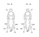
- the exercise assisting device includes a support unit 1 configured to bear a body of a user M (see FIG. 3 ), a drive device 2, and a housing 3.
- the support unit 1 includes a pair of foot supports 4 respectively configured to bear the left foot and right foot of the user M.
- the drive device 2 is configured to move the foot supports 4 to move the body of the user M with one's feet resting on the foot supports 4 respectively so as to vary a load applied to a lower limb of the user M.
- the support unit 1 and drive device 2 are housed in the housing 3.
- the housing 3 includes a base plate 30 used as a carrier to be placed on a floor, and designed to have a rectangular parallelepiped shape.
- the pair of the foot supports 4 and drive device 2 are disposed on the base plate 30.
- the base plate 30 in the present embodiment is configured to have the rectangular parallelepiped shape, although not limited to a peripheral shape.
- the base plate 30 is illustrated to have a top surface parallel to the floor when it is placed on the floor. Accordingly, a vertical dimension in FIG. 1B is equal to a vertical dimension of the exercise assisting device to be in use.
- An upper plate 31 is disposed above the base plate 30, and is coupled thereto to constitute a housing 3, It is noted that an arrow X in FIG. 2 denotes a forward direction of the housing 3. The upper plate 31 is not shown in FIG. 2 .
- the upper plate 31 is formed with two openings 31 a extending in a thickness direction of the upper plate 31 to expose the foot supports 4, respectively.
- the openings 31 a are each formed into a rectangular shape.
- the openings 31a have their longitudinal center lines extending in a crossing relation with respect to the back-and-forth direction of the housing 3 such that the distance between the center lines is greater at the front ends of the openings 31a than at the rear ends thereof.
- Each of the foot supports 4 has a bearing member 40 that is a footrest where the user M rests one's foot.
- the foot support 4 for bearing the left foot of the user M is represented as the left foot support 4A
- the foot support 4 for bearing the right foot of the user M is represented as the right foot support 4B .
- the foot supports 4 are designed in a similar manner. Therefore, an explanation is made to the left foot support 4A with reference to FIG. 1B , and an explanation concerning the right foot support 4B is omitted.
- the left foot support 4A has the bearing member 40 where the user M rests one's left foot.
- the bearing member 40 is formed into a rectangular plate to have such dimensions as to bear the entire foot of the user M.
- the bearing member 40 has a bearing surface (upper surface in FIG. 1B ) where the user M rests ones' foot and is made of a material or shaped to have a large coefficient of friction.
- the load detection unit 5 is configured to detect a load applied to the bearing member 40 and has two load sensors 50.
- One load sensor 50 (represented by a reference number 50A, as necessary) is provided to an outer portion (left portion in FIG. 1B ) 40a of the bearing member 40 corresponding to an outer part of user's foot.
- the other load sensor 50 (represented by a reference number 50B, as necessary) is provided to an inner portion (right portion in FIG. 1B ) 40b of the bearing member 40 corresponding to an inner part of the user's foot. That is, the load detection unit 5 includes the load sensor 50A configured to detect a load applied to the outer portion 40a and load sensor 50B configured to detect a load applied to the inner portion 40b.
- a sensor made of semiconductors is adopted as the load sensor 50.
- a load cell utilizing a strain gauge can be adopted as the load sensor 50.
- the basement 41 There is a basement 41 disposed below the bearing member 40 (between the base plate 30 and the bearing member 40) and rotatively coupled to the bearing member 40.
- the basement 41 has an opposite surface (upper surface, in FIG. 1B ) opposite to the inner portion 40b of the bearing member 40, and the opposite surface is provided with a side wall portion 42.
- the side wall portion 42 is provided at its apex with a tilting axle 43 to be rotatively connected to the bearing member 40.
- the inner portion 40b of the bearing member 40 is provided at its lower surface (back surface) with a tilting bearing 44 having an axle hole 44a for the tilting axle 43.
- the tilting axle 43 is formed such that its central axis extends along a forward/rearward direction of the foot of the user M.
- To rotate the bearing member 40 around the tilting axle 43 can tilt the bearing member outward (leftward, in FIG. 1B ) or inward (rightward, in FIG. 1B ) with regard to the foot of the user M.
- the bearing surface of the bearing member 40 where the user M rests one's left foot can be tilted as the bearing member 40 is tilted.
- the tilt adjusting unit 45 is configured to adjust a tilt of the bearing member 40.
- the tilt adjusting unit 45 includes a rack 45a provided to a lower surface of the outer portion 40a of the bearing member 40, and further includes a gear 45b provided to the basement 41.
- the gear 45b meshes with the rack 45a.
- the tilt adjusting unit 45 further includes an adjusting motor 45c being a stepping motor (pulse motor) configured to rotate the gear 45b clockwise or counterclockwise.
- the basement 41 has a through hole for the rack 45a extending in a thickness direction thereof.
- the tilt adjusting unit 45 drives the adjusting motor 45c to rotate the gear 45b clockwise or counterclockwise.
- the rack 45a moves upward or downward in relative to the gear 45b as the gear 45b rotates or counterrotates.
- a movement of the rack 45a varies a distance between the bearing member 40 and the basement 41 is varied in an opposite end (the outer portion 40a of the bearing member 40) in a width direction of the foot support 4. Therefore, the tilt of the bearing member 40 varies. It is noted that the basement 41, side wall portion 42, tilting axle 43, tilting bearing 44, and tilt adjusting unit 45 are not shown in FIG. 2 .
- the left foot support 4A is provided with the load detection unit 5 configured to detect the load applied to the bearing member 40 (that is, the load applied by the left foot of the user M) and the tilting mechanism unit 6 configured to tilt the bearing member 40 inward or outward with regard to the foot (left foot).
- the right foot support 4B is provided with the load detection unit 5 configured to detect the load applied to the bearing member 40 (that is, the load applied by the user M 's right foot) and the tilting mechanism unit 6 configured to tilt the bearing member 40 inward or outward with regard to the foot (right foot).
- a suffix "A” is attached to the reference number of each of the load detection unit 5 and tilting mechanism unit 6 of the left foot support 4A
- a suffix " B " is attached to the reference number of each of the load detection unit 5 and tilting mechanism unit 6 of the right foot support 4B , as necessary.
- bearings 46 integrally formed on the lower surface of the basement 41.
- the bearings 46 are apart from each other in the width direction of the bearing member 40.
- An axle 48 penetrating through the legs 47a of the bearing plate 47 and the bearings 46 is used for a rotative coupling of the bearing member 47.
- the axle 46 is located along a width direction of the bearing member 40.
- the bearing member 40 can rotate around the axle 48 such that both ends thereof in its longitudinal direction move upwardly or downwardly relative to the bearing plate 47. It is noted that the bearing 46, bearing plate 47, and axle 48 are not shown in FIG. 1B .
- the bearing plate 47 is attached to an upper surface of a footrest cover (not shown).
- the footrest cover is slidably attached to the base plate 30.
- a truck 70 of U-shaped cross section is fixed to a bottom of the footrest cover to have its open end oriented downwardly.
- the truck 70 is provided on each exterior face with two wheels 71 .
- the base plate 30 is formed with two fixed rails 72 for each of the left and right foot supports 4A and 4B .
- the truck 70 is placed on the rails 72 with the wheels 71 roll in rail grooves 72a in an upper surface of the rails 72.
- a derailment prevention plate (not shown) is provided on the upper surface of the rail 72 for preventing the wheels 71 from running off the rail grooves 72a .
- the rails 72 extend in a direction different from a lengthwise direction of the openings 31a in the housing 3.
- the openings 31 a have their individual longitudinal center lines crossed with each other so as to be spaced by a larger distance at the forward ends than at the rearward ends.
- the rails 72 have their individual longitudinal directions crossed with each other in the like manner.
- the rails 72 are inclined in relation to the forward/rearward direction of the housing 3 at a large angle than the openings 31a.
- the rails 72 have its length inclined at an angle of 45°.
- the rails 72 are oriented to such a direction as to prevent an increase of shearing force acting on the knee joints while the left and right foot supports 4A and 4B are moved along the rails 72 in a condition that the user's feet are placed thereon with each center line of the feet aligned with each of the length of the openings 31a.
- each of the left and right foot supports 4A and 4B is located such that the longitudinal direction of each of the left and right foot supports 4A and 4B is inclined, for example, at an angle of 9° relative to the forward/rearward direction (the direction indicated by the arrow X). Therefore, the user can take a natural posture without suffering from twisted feet when standing on the left and right foot supports 4A and 4B.
- the present embodiment illustrates a preferred mode that the left and right foot supports 4A and 4B are moved along the individual travel paths of shifting their positions both in the forward/rearward direction and the lateral direction, it is possible to determine the orientation of the rails 72 such that the left and right foot supports 4A and 4B are moved either in the forward/rearward direction or the lateral direction.
- the left and right foot supports 4A and 4B are allowed to reciprocate respectively along the length of the rails 72. Because of that the rails 72 have their length crossed respectively with the lengthwise center lines of the openings 31a, the bearing member 40 is allowed to move within the openings 31a along the direction crossing with the lengthwise direction of the openings 31 a.
- the truck 70, wheels 71, and rails 72 constitute a guide 7 restricting the travel path of each of the left and right foot supports 4A and 4B. It is noted that FIG. 1B shows the simplified guide 7.
- the drive device 2 is provided in order to move the pair of foot supports 4 respectively.
- the drive device 2 includes a drive motor 20, which is a rotary motor, as a driving source generating a rotary driving force to move the pair of foot supports 4.
- the drive device 2 further includes a router 21 and reciprocators 22.
- the router 21 is configured to transmit the rotary driving force of the motor 20 to the left and right foot supports 4A and 4B.
- the reciprocators 22 in configured to use the driving force to reciprocate the trucks 70 respectively along the rails 72.
- the present embodiment is configured to divide the driving force at the router 21 and transmit the divided driving force to the reciprocators 22, it is equally possible to generate the reciprocating driving force at the reciprocator 22 and divide the same at the router 21.
- the router 21 includes a worm (first gear) 21a and a pair of worm wheels (second gears) 21 b.
- the worm 21a is coupled to an output shaft 20a of the driving motor 20.
- Each of the worm wheels 21 b meshes with the worm 21 a.
- the worm 21a and the two worm wheels 21 b are held within a gearbox (not shown) fixed to the base plate 30.
- a pair of bearings (not shown) is provided inside the gear box. The pair of bearings is configured to bear the opposite longitudinal ends of the worm 21 a.
- a rotary shaft 21c Extending through the worm wheel 21 b is a rotary shaft 21c which is housed in the gear box.
- the rotary shaft 21 c is coupled to the worm wheel 21 b to be driven thereby to rotate.
- the rotary shaft 21 c is formed at its upper end with a coupling section 21d with non-circular cross-section (rectangular one in the illustrated instance),
- the reciprocator 22 includes a crank plate 22a, a crank shaft 22b, and a crank rod 22c.
- the crank plate 22a is coupled at its one end to the coupling section 21 d of the rotary shaft 21c.
- the crank rod 22c is coupled to the crank plate 22a by means of the crank shaft 22b.
- the crank shaft 22b has its one end fixed to the crank plate 22a and has the other end received in a bearing 22d carried on one end of the crank rod 22c. That is, the crank rod 22c has its one end rotatively coupled to the crank plate 22b, while the other end of the crank rod 22c is coupled to the truck 70 by means of an axle 22e so as to be rotatively coupled thereto.
- the crank rod 22c functions as a motion converter to translate the rotary motion of the worm wheel 21 b into a reciprocatory motion of the truck 70.
- the crank rod 22c is provided for each of the worm wheels 21 b.
- the trucks 70 are provided respectively to the left and right foot supports 4A and 4B. Therefore, the crank rods 22c function as the individual motion converters for translating the rotary motion of the worm wheels 21 b into the reciprocating motions of the left and right foot supports 4A and 4B.
- the truck 70 has its travel path restricted by the wheels 71 and the rails 72.
- the truck 70 reciprocates along the length of the rails 72 as the worm wheel 21 b rotates. That is, the rotation of the motor 20 is transmitted to the crank plate 22b by way of the worm 21a and the worm wheel 21b, so that the crank rod 22c coupled to the crank plate 22b causes the truck 70 to reciprocate linearly along the rails 72.
- the left and right foot supports 4A and 4B are driven to reciprocate respectively along the length of the rails 72.
- the worm 21 a and the two worm wheels 21 b are responsible for routing the driving force into two channels respectively for driving the left and right foot supports 4A and 4B so that the drive unit 2 drives the left and right foot supports 4A and 4B in a manner linked to each other.
- the worm wheels 21 b are engaged with the worm 21a at different portions spaced apart by 180° such that the right foot support 4B comes to the forward end of its movable range when the left foot support 4A comes to the rear end of its movable range.
- the left and right foot supports 4A and 4B shift in the same direction along the lateral direction.
- the phase difference of 180° is effective to minimize the shifting of the user's weight in the forward/rearward direction, enabling the exercise even by the user suffering from lowered balancing capability.
- the device necessitates the shifting movement of the user's weight in the forward/rearward direction, thereby developing an exercise not only for the leg muscles but also for lower back muscles of the user maintaining the balancing capability.
- each of the foot supports 4 is allowed to rotate around the axle 48. Therefore, it is possible to vary the height positions of the forward end as well as the rearward end of the bearing member 40.
- the height positions of the toe and the heel of the foot placed on the bearing member 40 can be varied for enabling the plantarflexion and dorsiflexion of the ankle joint.
- the present embodiment adopts the following structure in order to link the swinging movement of the bearing member 40 about the axle 48 with the reciprocating movement thereof along the rail 72. That is, the base plate 30 is provided at a portion along the travel path of the bearing member 40 with a guide surface (not shown) including an inclination. In this connection, the basement 41 is provided on its bottom with a follower projection (not shown) which comes into engagement with the guide surface.
- the follower projection has at its top a roller which comes into rolling contact with the guide surface.
- the follower projection has the roller, it is suffice that the follower projection is formed from a material and/or shaped into a configuration to have a tip of small coefficient of friction.
- the follower projection which is arranged to come into rolling contact with the guide surface, rides up and down the inclination of the guide surface while each of the foot supports 4 is driven by the drive motor 20 to reciprocates, thereby swinging the basement 41 about the axle 48 to vary tilt angles of the bearing member 40 and basement 41 relative to the base plate 30, and therefore enabling the plantarflexion and dorsifilexion at the ankle joint.
- control unit 8 is configured to perform a control of the drive device 2 (an operation control of the drive motor 20 of the drive device 2) as well as a control of the tilting mechanism unit 6 (an operation control of the adjusting motor 45c of the tilting mechanism unit 6) .
- the control unit 8 is, for example, a micro computer.
- the control unit 8 controls an electrical power supplied to the drive motor 20 or adjusting motor 45c from a power source not shown, thereby activating the drive motor 20, deactivating the drive motor 20, or adjusting the number of rotations of the drive motor 20. Further, the control unit 8 is configured to activate the drive motor 20 when a switch (not shown) provided on the housing 3 is turned on, and to deactivate the drive motor 20 when the switch is turned off.
- the control unit 8 further is configured to supply pulse power to the adjusting motor 45c of the tilting mechanism unit 6 from the power source to adjust the tilt of the bearing member 40.
- the control unit 8 adjusts the tilt of the bearing member 40 with reference to detection result of the respective load detection units 5.
- the control unit 8 controls the tilting mechanism unit 6, that is, tilts the bearing member 40 so as to reduce a difference between loads detected by two load sensors 50A and 50B of the load detection unit 5 respectively.
- the control unit 8 controls the tilting mechanism unit 6 such that the difference between the loads detected by two load sensors 50A and 50B respectively becomes around 0 (that is, the load detected by the load sensor 50A becomes equal to the load detected by the load sensor 50B).
- the load detection unit 5 including the two load sensors 50, tilting mechanism unit 6, and control unit 8 constitute a tilting device A configured to tilt the bearing member 40 so as to reduce a difference between the load applied to the outer portion 40a of the bearing member 40 and the load applied to the inner portion 40b of the bearing member 40.
- the switch is kept turned off and the left and right foot supports 4A and 4B are located at predetermined initial positions respectively.
- the left and right foot supports 4A and 4B are located at the same level along the forward/rearward direction. That is, the left and right foot supports 4a and 4B lie on a line extending along the lateral direction when they are at the initial positions. Accordingly, when the user stands on the left and right foot supports 4A and 4B of the initial positions, a vertical line depending from the weight center of the user passes through a center between the left and right foot supports 4A and 4B.
- the tilt of the bearing member 40 is adjusted such that the load detected by the load sensor 50A becomes equal to the load detected by the load sensor 50B. Therefore, at the initial condition, the bearing surface of the bearing member 40 is almost kept parallel to a horizontal plane unless the user M rests one's foot on the foot support 4.
- the bearing member 40 is tilted so as to raise the outer portion 40a relative to the inner portion 40b (that is, the bearing member 40 is tilted inward) by the tilting device A (see FIG. 3B ).
- the bearing member 40 is caused to tilt continuously until the difference between the loads respectively detected by two load sensors 50A and 50B becomes zero While the outer portion 40a of the bearing member 40 is raised to a higher position than the inner portion 40b, the load applied to the inner part of the lower limb is increased to a greater extent than in a condition where the user's foot has its width direction kept parallel to the horizontal plane (i.e., the bearing surface of the bearing member 40 lies in the horizontal plane). Accordingly, it is possible to intensively train the inner part of the muscles of the lower limb. It is not required that the difference between the loads is kept 0 in a strict sense. It is sufficient that the difference between the loads is kept around 0.
- the bearing member 40 is tilted so as to raise the inner portion 40b relative to the outer portion 40a (that is, the bearing member 40 is tilted outward) by the tilting device A. Further, as described in the above, the bearing member 40 is kept being tilted until the difference between the loads detected by two load sensors 50A and 50B respectively becomes zero.
- the load applied to the inner part of the lower limb is increased by comparison with the condition where the foot breadth direction is kept parallel to the horizontal direction (the bearing surface of the bearing member 40 is kept parallel to the horizontal plane). Accordingly, it is possible to intensively train the inner part of the muscles of the lower limb. It is not required that the difference between the loads is kept 0 in a strict sense. It is sufficient that the difference between the loads is kept around 0.
- the tilting device A does not tilt the bearing member 40.
- the switch is turned on in order to operate the exercise assisting device from the initial condition.
- the control unit 8 supplies an electrical power to the drive motor 20 to activate the drive motor 20.
- the drive motor 20 can drive the left and right foot supports 4A and 4B to move in the forward/rearward direction and at the same time to move in the lateral direction in the linked manner to each other.
- the left and right foot supports 4A and 4B are driven to reciprocate linearly along the rails 72, respectively, so as to move in directions different from the lengthwise directions of the feet.
- the left and right foot supports 4A and 4B move in the directions inclined at an angle of 45° relative to the forward/rearward direction of the housing 3, over the travel distance of 20 mm, for example.
- the bearing member 40 and basement 41 is driven to swing about the axle 48 as each of the left and right foot supports 4A and 4B reciprocates along the rail 72. While the bearing member 40 is moving, the follower projection rides up and down the inclination of the guide surface to cause the dorsiflexion of the ankle joint when each of the left and right foot supports 4A and 4B comes to its forward end position, and the plantarflexion when it comes to its rearward end position.
- the axle 48 is positioned nearer to the heel within the length of the foot bottom.
- Each of the dorsiflexion and plantarflexion is realized at the tilt angle of about 10° relative to a reference plane defined by the upper surface of the base plate 30.
- the dorsiflexion and the plantarflexion can be made respectively at the rearward end position and the forward end position of each of the left and right foot supports 4A and 4B in opposite relation to the above.
- the tilt angle relative to the reference plane can be selected differently from the above mentioned angle. Such modified operation can be easily realized by an appropriate shaped guide surface.
- the exercise assisting device of the present embodiment has the user M make the passive exercise by means of moving the left and right foot supports 4A and 4B as described in the above.
- the bearing member 40 is tilted so as to reduce the difference between the load applied to the outer portion 40a of the bearing member 40 and the load applied to the inner portion 40b of the bearing member 40. Therefore, while the load applied to the outer portion 40a of the bearing member 40 exceeds the load applied to the inner portion 40b of the bearing member 40 (that is, the user has bow legs), the load applied to the inner part of the lower limb is increased to a greater extent than in a condition where the user's foot has its width direction kept parallel to a horizontal plane. Accordingly, it is possible to intensively train the inner part of muscles of the lower limb.
- the load applied to the inner portion 40b of the bearing member 40 exceeds the load applied to the outer portion 40a of the bearing member 40 (that is, the user has knock knees)
- the load applied to the outer part of the lower limb is increased to a greater extent than in a condition where the user's foot has its width direction kept parallel to the horizontal plane. Accordingly, it is possible to intensively train the outer part of the muscles of the lower limb.
- it is possible to remedy deformed bones of the lower limb that is, it is possible to recover a skeletal alignment of the lower limb).
- the user can enjoy a comfortable passive exercise (training) while being alleviated of the knee pain, which means that even the user suffering from knee pains during one's walking can make the passive exercise.
- the control unit is configured to control the tilting mechanism unit 6 so as to reduce the difference between loads detected by the two load sensors 50A and 50B respectively, thereby tilting the bearing member 40 inward or outward. Therefore, it is possible to adjust the tilt of the bearing member 40 to be a tilt suitable for the user M.
- a configuration of the tilting mechanism unit 6 is not limited to the above instance.
- a conventional configuration such as a set of a rotary motor and feed screw, a set of a rotary motor and belt, a set of a rotary motor and pantograph mechanism, a linear movement mechanism utilizing a solenoid coil, and a liner movement mechanism utilizing an air-bag can be adopted as the configuration of the tilting mechanism unit 6.
- the router 21 is configured to have the worm 21 a and the worm wheels 21 b for realizing the power transmission from the output shaft 20a of the drive motor 20 to the rotary shaft 21c of the worm wheel 21 b with speed reduction.
- a belt can be utilized to transmit the power from the output shaft 20a of the drive motor 20 to the rotary shaft 21c perpendicular to the output shaft 20a.
- a pulley is utilized to receive the belt while dispensing with the worm 21 a.
- the drive motor 20 has its output shaft 20a extending along the upper surface of the base plate 30.
- spur gearing is adopted to achieve the transmission and routing of the rotary power, instead the combination of the worm 21a and the worm wheels 21 b.
- pulleys and a belt may be used in place of the spur gearing for transmission of the rotary power between the pulleys.
- the reciprocator 22 may be composed of a grooved cam driven to rotate by the drive motor 20 and a cam follower engaged in a groove of the cam.
- the grooved cam can be used instead of the worm wheel 21b and be arranged to have its rotation axis parallel to the output shaft 20a of the drive motor 20 for power transmission from the output shaft 20a to the grooved cam through a pinion.
- two cam followers can be used for engagement respectively with the cam grooves of the cams such that the grooved cam and the cam followers are cooperative to function as the router 21 as well as the reciprocators 22.
- the illustrated embodiment has the base plate 30 formed with the guide surface and the basement 41 formed with the follower projection, the same operation can be achieved with a configuration in which the basement 41 is provided with the guide surface and the base plate 30 is provided with the follower projection.
- the exercise assisting device of the present embodiment includes the load detection unit 5, the exercise assisting device sets automatically the tilt of the bearing member 40.
- the load detection unit 5 is optional. That is, the exercise assisting device may be configured to enable the user to adjust manually the tilt of the bearing member 40 based on one's foot condition (e.g. bow legs or knock knees). In this instance, it is sufficient that an operation unit (not shown) for operating the tilting mechanism unit 6 is provided to the housing 3.
- the exercise assisting device of the present embodiment is configured to be adapted in use to be placed on a floor
- the exercise assisting device can be used with its portion embedded in the floor.
- a selection is made as to whether the exercise assisting device is placed at a fixed position or movably supported.
- the exercise assisting device of the present embodiment is different in the configuration of the tilting device A from the exercise assisting device of the first embodiment.
- Other components of the exercise assisting device of the present embodiment are the same as those of the first embodiment. Therefore the other components are designated by like reference numerals and dispensed with duplicate explanations.
- the load detection unit 5 includes the load sensor 50 configured to detect the load applied to the inner portion 40b of the bearing member 40.
- the load detection unit 5 of the present embodiment includes only one load sensor 50.
- the control unit 8 of the present embodiment is configured to control the tilting mechanism unit 6 based on the load detected by the one load sensor 50.
- the control unit 8 is configured to make a comparison of the load detected by the load sensor 50 with a predetermined threshold, and determine the difference between the load applied to the outer portion 40a of the bearing member 40 and the load applied to the inner portion 40b of the bearing member 40 based on the resultant comparison.
- the predetermined threshold is, for example, the load applied to the inner portion 40b in a condition where the user M applies the same load to the outer portion 40a and inner portion 40b of the bearing member 40.
- the difference between the load applied to the outer portion 40a and the load applied to the inner portion 40b is determined by a difference between the predetermined threshold and the load detected by the load sensor 50.
- the predetermined threshold can be estimated from body weight of the user M. It is sufficient that the user M inputs own body weight to the exercise assisting device in preparation to use the exercise assisting device.
- the predetermined threshold can be estimated from the loads detected by the load sensors of the load detection unit 5 of the respective foot supports 4.
- the control unit 8 has not only the predetermined threshold but also a judgment value as a value to be compared with the load detected by the load sensor 50.
- the judgment value is a value used for judging whether or not the user M rests one's foot on the foot support 4.
- the control unit 8 is configured to judge that the user M does not rest one's foot on the foot support 4 when the load detected by the load sensor 50 is less than the judgment value. In this case, the control unit 8 controls the tilting mechanism unit 6 such that the bearing surface of the bearing member 40 of each of the foot supports 4 is kept parallel to the horizontal plane.
- the control unit 8 of the present embodiment supplies the pulse power to the adjusting motor 45c of the tilting mechanism unit 6 from the power source to adjust the tilt of the bearing member 40, thereby reducing the difference between the load applied to the outer portion 40a and the load applied to the inner portion 40b.
- the control unit 8 inclines the bearing member 40 such that the load detected by the load sensor 50 becomes equal to the threshold.
- the load detection unit 5, tilting mechanism unit 6, and control unit 8 constitute the tilting device A.
- the load detected by the load sensor 50 is less than the judgment value unless the user M rests one's foot on the foot support 4.
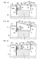
- the control unit 8 controls the tilting mechanism unit 6 such that the bearing surface of the bearing member 40 is kept parallel to the horizontal plane (see FIG. 4A ).
- a following operation is performed when the user M rests one's foot on the foot support 4.
- the bearing member 40 when the load applied to the outer portion 40a of the bearing member 40 exceeds the load applied to the inner portion 40b of the bearing member 40, the bearing member 40 is inclined so as to raise the outer portion 40a to a higher position than the inner portion 40b (that is, the bearing member 40 is inclined inward) by the tilting device A (see FIG. 4B ).
- the bearing member 40 is caused to tilt continuously until the difference between the threshold and the load detected by the load sensor 50 becomes zero While the outer portion 40a of the bearing member 40 is raised to a higher position than the inner portion 40b, the load applied to the inner part of the lower limb is increased by a greater extent than in the condition where the user's foot has its width direction kept parallel to the horizontal plane (i.e., the bearing surface of the bearing member 40 lies horizontally). Accordingly, it is possible to intensively train the inner part of the muscles of the lower limbs.
- the bearing member 40 when the load applied to the inner portion 40b of the bearing member 40 exceeds the load applied to the outer portion 40a of the bearing member 40, the bearing member 40 is inclined so as to raise the inner portion 40b to a higher position than the outer portion 40a (that is, the bearing member 40 is tilted outward) by the tilting device A (see FIG. 4C ). As described in the above, the bearing member 40 is caused to tilt continuously until the difference between the threshold and the load detected by the load sensor 50 becomes zero.
- the load applied to the inner part of the lower limb is increased to a greater extent than in the condition where the user's foot has its width direction kept parallel to a horizontal plane (i.e., the bearing surface of the bearing member 40 is kept parallel to the horizontal plane). Accordingly, it is possible to intensively train the inner part of the muscles of the lower limb.
- the tilting device A When the load applied to the inner portion 40b of the bearing member 40 is equal to the load applied to the outer portion 40a of the bearing member 40, the tilting device A does not incline the bearing member 40 (see FIG. 4A ).
- the user M can make the aforementioned passive exercise by turning on the switch after resting one's feet respectively on the foot supports 4.
- the bearing member 40 is tilted so as to reduce the difference between the load applied to the outer portion 40a of the bearing member 40 and the load applied to the inner portion 40b of the bearing member 40. Therefore, it is possible to intensively train the inner part of muscles of the lower limb when the user has bow legs. Further, it is possible to intensively train the outer part of muscles of the lower limb when the user has knock knees. Thus, it is possible to improve balancing or remedy capacity imbalance between the outer and inner parts of the muscles of the lower limb, even if the user has bow legs or knock knees.
- the user can enjoy a comfortable passive exercise (training) while being alleviated of the knee pain, which means that even the user suffering from knee pains during one's walking can make the passive exercise.
- the bearing member 40 is inclined inward or outward with regard to the user's foot based on the load detected by the load sensor 50 of the load detection unit 5. Therefore, it is possible to adjust the tilt of the bearing member 40 to be a tilt suitable for the user. Notably, according to the present embodiment, it is possible to reduce a production cost because of that the number of the load sensor 50 of the load detection unit 5 can be reduced to one.
- the load sensor 50 is configured to detect the load applied to the inner portion 40b
- the load sensor 50 may be configured to detect the load applied to the outer portion 40a.
- the predetermined threshold can be the load applied to the outer portion 40a in a condition where the user M applies the same load to the outer portion 40a and inner portion 40b of the bearing member 40.
- the control unit 8 of the above mentioned instance is configured to control the tilting mechanism unit 6 to incline the bearing member such that the load detected by the load sensor 50 becomes equal to the threshold
- the control unit 8 of another instance is configured to vary a tilt angle of the bearing member 40 in a stepwise fashion.
- control unit 8 inclines the bearing member 40 outward at a predetermined angle relative to the horizontal plane when the load detected by the load sensor 50 is not less than a first threshold.
- the control unit 8 inclines the bearing member 40 inward at a predetermined angle relative to the horizontal plane when the load detected by the load sensor 50 is not greater than a second threshold.
- the control unit 8 keeps the bearing member 40 horizontal when the load detected by the load sensor 50 exceeds the second threshold and is less than the first threshold.
- FIGS. 5A to 5C illustrates the exercise assisting device of another embodiment of the present invention.
- the exercise assisting device shown in FIG. 5 is different in the configuration of the foot support 4 from the exercise assisting device shown in FIG. 4 and the exercise assisting device of the first embodiment.
- Other components of the exercise assisting device shown in FIG. 5 are the same as those of the exercise assisting device shown in FIG. 4 and the exercise assisting device of the first embodiment. Therefore the other components are designated by like reference numerals and dispensed with duplicate explanations.
- the foot support 4 shown in FIG. 5 is provided with a pair of air bags (air cells) 60 configured to define a distance between the bearing member 40 and the basement 41.
- the air bags 60 are the same in form.
- One air bag 60 is located so as to bear the outer portion 40a of the bearing member 40, and another air bag 60 is located so as to bear the inner portion 40b of the bearing member 40. Therefore, the bearing member 40 is inclined when one air bag 60 expands or shrinks relative to another air bag 60.
- the exercise assisting device shown in FIG. 5 has the tilting mechanism unit 6 composed of the pair of air bags 60.
- the housing 3 is configured to house an air pump (not shown) configured to supply air to each of the air bags 60.
- the basement 41 is provided at opposite ends in its width direction with a regulation member 41 b.
- the regulation member 41 b is configured to define a range within which the bearing member 40 is allowed to tilt.
- the air bag 60 is provided with a valve member (not shown).
- the valve member is configured to close an exhaust port 60a of the air bag 60 until pressure inside the air bag 60 exceeds a predetermined value.
- the predetermined value is selected to enable the air pump to supply sufficient air to the air bag 60 such that the bearing surface of the bearing member 40 of the foot support 4 is kept parallel to the horizontal plane.
- the predetermined value is a value where the air bag 60 which bears the bearing member 40 such that the bearing surface is kept parallel to the horizontal plane does not eject air.
- a holder 40c is provided to each of the outer portion 40a and inner portion 40b of the bearing member 40 shown in FIG. 5 .
- a through hole 40d for an exhaust valve 49 extends through a portion of the bearing member 40 opposite to the holder 40c in a thickness direction thereof.
- the exhaust valve 49 is formed into a L-shape including a valve portion 49a configured to gate the exhaust port 60 and a load detection portion 49b integrally formed on the valve portion 49a so as to extend laterally from the valve portion 49a.
- the valve portion 49a penetrates through the through hole 40d.
- the exhaust valve 49 is adapted in use to forcibly close the exhaust port 60a of the air bag 60.
- An elastic member 51 is interposed between the bearing member 40 and the load detection portion 49b of the exhaust valve 49.
- the elastic member 51 is made of an elastic material such as a rubber so as to shrink upon receiving a load not less than a prescribed value. While the load applied to the elastic member 51 is not greater than the prescribed value, the elastic member 51 keeps the exhaust valve 49 in a position where the exhaust valve 49 opens the exhaust port 60a. By contrast, when the load applied to the elastic member 51 exceeds the prescribed value, the elastic member 51 shrinks so as to allow the exhaust valve 49 to move to a position where the exhaust valve 49 closes the exhaust port 60.
- the prescribed value[s] is [a value] slightly less than the load applied to the outer portion 40a (or inner portion 40b) in a condition where the user M applies the same load to the outer portion 40a and inner portion 40b of the bearing member 40. It is noted that the elastic member 51 may be of known configuration and therefore no detailed explanation thereof is deemed necessary.
- the air bag 60, exhaust valve 49, and elastic member 51 constitute the tilting device A.
- a suffix "A” is attached to the reference number of each of the air bag 60, exhaust valve 49, and elastic member 51 corresponding to the outer portion 40a
- a suffix "B” is attached to the reference number of each of the air bag 60, exhaust valve 49, and elastic member 51 corresponding to the inner portion 40b, as necessary.
- the air pump supplies air to each air bag 60 such that the bearing surface of the bearing member 40 is kept parallel to the horizontal plane.
- the valve member closes the exhaust port 60a of the air bag 60 before the user M rests one's foot on the foot support 4. Therefore, as shown in FIG. 5A , the pair of air bags 60 bears the bearing member 40 such that the bearing surface is kept parallel to the horizontal plane.
- a following operation is performed.
- the valve members of each of the air bags 60A and 60B open the corresponding exhaust port 60a at an approximately-same timing.
- the elastic members 51A and 51B start to shrink at an approximately-same timing. Therefore, the exhaust valves 49A and 49B close the exhaust ports 60a of each of the air bags 60A and 60B open at an approximately-same timing.
- the bearing member 40 is not inclined, and the bearing surface is kept parallel to the horizontal plane.
- each of the air bags 60A and 60B ejects air from its inside.
- the elastic member 51A shrinks before the elastic member 51B shrinks. That is, the exhaust port 60a of the air bag 60A is closed prior to closing of the exhaust port 60a of the air bag 60B.
- the air bag 60A acts to keep the outer portion 40a of the bearing member 40 spaced by a constant distance from the basement 41 (see FIG. 5B ). This causes the increase of the load applied to the inner portion 40b, followed by the elastic member 51B being caused to start shrinking.
- the exhaust port 60a of the air bag 60B is closed, and the air bag 60B acts to keep the inner portion 40b of the bearing member 40 spaced by a constant distance from the basement 41 (see FIG. 5C ).
- the air bag 60A having its exhaust port 60a closed prior to closing of the exhaust port 60a of the air bag 60B holds a greater volume of the air than the air bag 60B whose exhaust port 60a is closed subsequent to closing of the exhaust port 60a of the air bag 60A.
- the distance between the basement 41 and the bearing member 40 is made greater towards the outer portion 40a than at the inner portion 40b.
- the bearing member 40 is inclined inward with regard to the foot of the user M.
- each of the air bags 60A and 60B ejects air from its inside.
- the elastic member 51B shrinks before the elastic member 51A shrinks. That is, the exhaust port 60a of the air bag 60B is closed prior to closing of the exhaust port 60a of the air bag 60A.
- the air bag 60B acts to keep the inner portion 40b of the bearing member 40 spaced by a constant distance from the basement 41. This causes the increase of the load applied to the outer portion 40a, followed by the elastic member 51A being caused to start shrinking.
- the exhaust port 60a of the air bag 60A is closed, and the air bag 60A acts to keep the outer portion 40a of the bearing member 40 spaced by a constant distance from the basement 41 .
- the air bag 60B having its exhaust port 60a closed prior to closing of the exhaust port 60a of the air bag 60A holds a greater volume of the air than the air bag 60A whose exhaust port 60a is closed subsequent to closing of the exhaust port 60a of the air bag 60B.
- the distance between the basement 41 and the bearing member 40 is made greater towards the inner portion 40b than at the outer portion 40a.
- the bearing member 40 is inclined inward with regard to the foot of the user M.
- the exercise assisting device shown in FIGS. 5A to 5C is capable of tilting the bearing member 40 so as to reduce the difference between the load applied to the outer portion 40a of the bearing member 40 and the load applied to the inner portion 40b of the bearing member 40. Therefore, it is possible to improve a balance (capacity imbalance) between the outer part and the inner part of the muscles of the lower limb. As a result, it is possible to remedy the deformed bones of the lower limb (that is, it is possible to recover the skeletal alignment of the lower limb). Further, the user can enjoy a comfortable passive exercise (training) while being alleviated of the knee pain, which means that even the user suffering from knee pains during one's walking can make the passive exercise. Moreover, it is possible to reduce a production cost because an electric circuit for the load detection unit 5 or the like is made redundant.
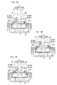
- the bearing member 40 of the exercise assisting device shown in FIGS. 5A to 5C is a one board, for example, the bearing member 40 may be divided into two in its width direction as shown in FIG. 6A .
- the exercise assisting device shown in FIG. 6A has a basic structure similar to that shown in FIG. 5 . Therefore like parts are designated by like reference numerals and dispensed with duplicate explanations.
- the bearing member 40 is divided into the outer portion 40a formed into a rectangular plate and the inner portion 40b formed into a rectangular plate.
- the outer portion 40a and inner portion 40b are rotatively coupled to the side wall portions 42 provided on the center of the basement 41 in its width direction by use of the tilting axle 43 and the tilting bearing 44, respectively. Accordingly, in the instance shown in FIG. 6A , the outer portion 40a and inner portion 40b are separately inclined each other.
- the air bag 60, exhaust valve 49, and elastic member 51 constitute the tilting device A.
- the tilting device A may be configured to tilt at least one part of the bearing member 40 so as to reduce the difference between the load applied to the outer portion 40a of the bearing member 40 and the load applied to the inner portion 40b of the bearing member 40.
- the bearing member 40 is not limited to the above mentioned instance, and may be configured to be capable of varying a balance between the load applied to the outer portion 40a of the bearing member 40 and the load applied to the inner portion 40b of the bearing member 40 .
- FIGS. 5 and FIG. 6 utilize shrinkage of the air bag 60 in order to incline the bearing member 40. Further, another instance may be configured to control the air pump to supply air to the air bag 60 so as to expand the same, thereby inclining the bearing member 40.
- the holders 40c are positioned below the rear surfaces of the outer portion 40a and inner portion 40b of the bearing member 40 respectively, and are rotatively coupled to the tilting axles 43 together with the outer portion 40a and inner portion 40b, respectively.
- the outer portion 40a and inner portion 40b of the bearing member 40 respectively are formed with protrusions 40e used as a valve for the exhaust port 60a.
- the elastic member 51 is interposed between the holder 40c and each of the outer portion 40a and inner portion 40b (the elastic member 51 is not shown in FIG. 6B ).
- the elastic member 51 is configured to shrink upon receiving the load greater than a predetermined load such that the protrusion 40e closes the exhaust port 60a.
- the predetermined load is equal to the load applied to the outer portion 40a (or inner portion 40b) in a condition where the user M applies the same load to the outer portion 40a and inner portion 40b of the bearing member 40.
- the air bag 60 is interposed between the holder 40c and the basement 41.
- Each air bag 60 has an air supply port 60b connected to the aforementioned air pump.
- the air pump is configured to supply air to (pressurize) the each air bag 60 such that the bearing surfaces of each of the outer portion 40a and inner portion 40b of the bearing member 40 are kept parallel to the horizontal plane while the user M keeps applying the loads equally to the outer portion 40a and inner portion 40b of the bearing member 40.
- the elastic member 51A shrinks before the elastic member 51B shrinks. That is, the exhaust port 60a of the air bag 60A is closed prior to closing of the exhaust port 60a of the air bag 60B. Therefore, the air bag 60A expands as being supplied with the air from the air pump, thereby lifting the outer portion 40a. This causes an increase of the load applied to the inner portion 40b (that is, the load applied to the elastic member 51B ), thereby shrinking the elastic member 51B.
- the shrinkage of the elastic member 51B causes closing of the exhaust port 60a of the air bag 60B.
- the exercise assisting device shown in FIG. 6B is capable of tilting the bearing member 40 so as to reduce the difference between the load applied to the outer portion 40a of the bearing member 40 and the load applied to the inner portion 40b of the bearing member 40. Therefore, it is possible to improve a balance (capacity imbalance) between the outer part and the inner part of the muscles of the lower limb. As a result, it is possible to remedy the deformation of bones of the lower limb (that is, it is possible to recover the skeletal alignment of the lower limb). Further, the user can enjoy a comfortable passive exercise (training) while being alleviated of the knee pain, which means that even the user suffering from knee pains during one's walking can make the passive exercise. Moreover, it is possible to reduce a production cost because an electric circuit for the load detection unit 5 or the like is made redundant.
- the technical feature of the present invention can be applied to the exercise assisting device shown in FIGS. 7A and 7B .
- the exercise assisting device shown in FIG. 7 includes a carrier 30 to be placed on a predetermined position such as a floor. There are a supporter 32 and a handle post 33 provided on the carrier 30.
- the supporter 32 is provided at its upper end with a seat 9 configured to bear the buttocks of the user M.
- the handle post 33 has handles 33a adapted in use to be held with the hand of the user M as necessary.
- the pair of foot supports 4 is attached to the carrier 30 and between the supporter 32 and the handle post 33. This foot support 4 has the same configuration as the foot support 4 of the first embodiment or the foot support 4 of respective FIGS 4 to 6 .
- the pair of foot supports 4 constitutes the support unit 1 together with the seat 9.
- the supporter 32 is provided with the drive device 2 configured to reciprocate the seat 9.
- the drive device 2 is configured to reciprocate the seat 9 which is one part of the support unit 1 by use of a driving source (not shown), thereby displacing the buttocks of the user M with one's feet resting respectively on the foot supports 4 and one's buttocks resting on the seat 9.
- the drive device 2 is configured to vary the weight acting on the legs of the user M.
- the drive device 2 displaces the buttocks of the user M, thereby varying a proportion of bearing the user's weight between the seat 9 and the foot supports 4. In this consequence, the drive device 2 varies the user's weight acting on the buttocks, thereby varying the weight acting on each of the feet of the user.
- a load applied to a femoral region of the user M is increased as a proportion of bearing the user's weight by the seat 9 is decreased.
- This is similar to bending user's own knee during a squat exercise and can trigger muscle contraction of femoral muscles. That is, an oscillation of the seat 9 induces a passive exercise not an active exercise of the user M. According to this passive exercise, the femoral muscles repeat tonus and laxity. Therefore, the user M can mainly exercise for own femoral muscles.
- the exercise assisting device shown in FIG. 7 is capable of tilting the bearing member 40 so as to reduce the difference between the load applied to the outer portion 40a of the bearing member 40 and the load applied to the inner portion 40b of the bearing member 40. Therefore, it is possible to improve a balance (capacity imbalance) between the outer part and the inner part of the muscles of the lower limb even if the user has bow legs or knock knees. As a result, it is possible to remedy the deformed bones of the lower limb (that is, it is possible to recover the skeletal alignment of the lower limb). Further, the user can enjoy a comfortable passive exercise (training) while being alleviated of the knee pain, which means that even the user suffering from knee pains during one's walking can make the passive exercise.
Landscapes
- Health & Medical Sciences (AREA)
- Physical Education & Sports Medicine (AREA)
- General Health & Medical Sciences (AREA)
- Life Sciences & Earth Sciences (AREA)
- Orthopedic Medicine & Surgery (AREA)
- Epidemiology (AREA)
- Biophysics (AREA)
- Pain & Pain Management (AREA)
- Rehabilitation Therapy (AREA)
- Animal Behavior & Ethology (AREA)
- Public Health (AREA)
- Veterinary Medicine (AREA)
- Cardiology (AREA)
- Vascular Medicine (AREA)
- Rehabilitation Tools (AREA)
- Residential Or Office Buildings (AREA)
Applications Claiming Priority (2)
| Application Number | Priority Date | Filing Date | Title |
|---|---|---|---|
| JP2007341355 | 2007-12-28 | ||
| PCT/JP2008/073273 WO2009084495A1 (ja) | 2007-12-28 | 2008-12-22 | 運動補助装置 |
Publications (1)
| Publication Number | Publication Date |
|---|---|
| EP2233178A1 true EP2233178A1 (de) | 2010-09-29 |
Family
ID=40824209
Family Applications (1)
| Application Number | Title | Priority Date | Filing Date |
|---|---|---|---|
| EP08866122A Withdrawn EP2233178A1 (de) | 2007-12-28 | 2008-12-22 | Übungsassistenzsystem |
Country Status (7)
| Country | Link |
|---|---|
| US (1) | US20100267534A1 (de) |
| EP (1) | EP2233178A1 (de) |
| JP (1) | JP5033198B2 (de) |
| KR (1) | KR20100108412A (de) |
| CN (2) | CN102652869A (de) |
| TW (1) | TW200934552A (de) |
| WO (1) | WO2009084495A1 (de) |
Cited By (2)
| Publication number | Priority date | Publication date | Assignee | Title |
|---|---|---|---|---|
| AT513954A1 (de) * | 2013-01-24 | 2014-08-15 | Krammer Wolfgang | Vorrichtung mit Platten |
| CN105498151A (zh) * | 2015-12-18 | 2016-04-20 | 宁波嘉达健康科技有限公司 | 一种健身器材上的配重负载系统 |
Families Citing this family (7)
| Publication number | Priority date | Publication date | Assignee | Title |
|---|---|---|---|---|
| KR101131973B1 (ko) | 2009-11-30 | 2012-03-29 | 주식회사 무한기업 | 반수동적 보행 재활 장치 |
| JP2013075126A (ja) * | 2011-09-30 | 2013-04-25 | Panasonic Corp | 動作訓練装置、動作訓練システム |
| CN103040470A (zh) * | 2012-12-26 | 2013-04-17 | 复旦大学附属华山医院 | 一种脚踝关节测试平台 |
| JP6336084B2 (ja) * | 2013-12-10 | 2018-06-06 | オペラシオン ソンリエ エス.エル.Operacion Sonrie S.L. | 体重の均衡維持を補助するためのシステム |
| CN106691770A (zh) * | 2015-11-12 | 2017-05-24 | 摩托瑞克有限公司 | 产生并执行训练课程程序 |
| DE102018133410A1 (de) * | 2018-12-21 | 2020-06-25 | Peter Wasmeier | Bedienvorrichtung |
| US11465031B2 (en) * | 2020-09-16 | 2022-10-11 | RevolutioNice, Inc. | Ambulation simulation systems, terrain simulation systems, treadmill systems, and related systems and methods |
Family Cites Families (11)
| Publication number | Priority date | Publication date | Assignee | Title |
|---|---|---|---|---|
| JPS6455131A (en) | 1987-08-25 | 1989-03-02 | Torikichi Yoneyama | Method for sexing and separating female and male egg |
| US5049079A (en) * | 1988-12-19 | 1991-09-17 | John H. Peterson | Closed loop ski simulation and instructional system |
| CN2162264Y (zh) * | 1992-11-21 | 1994-04-20 | 黄金镇 | 脚踏式运动器 |
| JP2917128B2 (ja) * | 1996-08-08 | 1999-07-12 | 谷 白糸 | 歩行体験装置 |
| JP3115241B2 (ja) * | 1996-10-07 | 2000-12-04 | 岡山県 | 歩行訓練・矯正装置 |
| JP2003245376A (ja) * | 2002-02-25 | 2003-09-02 | Kineshio:Kk | 脚足筋鍛錬具 |
| JP3991747B2 (ja) | 2002-03-29 | 2007-10-17 | 松下電工株式会社 | 訓練装置 |
| JP4148120B2 (ja) * | 2003-05-21 | 2008-09-10 | 松下電工株式会社 | 運動補助装置 |
| CN100540096C (zh) * | 2003-05-21 | 2009-09-16 | 松下电工株式会社 | 腿部训练设备 |
| CN2703549Y (zh) * | 2004-04-19 | 2005-06-08 | 萧雅曲 | 旋转式踏步机结构 |
| JP4736670B2 (ja) * | 2005-09-27 | 2011-07-27 | パナソニック電工株式会社 | 運動補助装置 |
-
2008
- 2008-12-22 US US12/746,978 patent/US20100267534A1/en not_active Abandoned
- 2008-12-22 JP JP2009548024A patent/JP5033198B2/ja not_active Expired - Fee Related
- 2008-12-22 EP EP08866122A patent/EP2233178A1/de not_active Withdrawn
- 2008-12-22 CN CN2011104273540A patent/CN102652869A/zh active Pending
- 2008-12-22 KR KR1020107016884A patent/KR20100108412A/ko not_active Abandoned
- 2008-12-22 WO PCT/JP2008/073273 patent/WO2009084495A1/ja not_active Ceased
- 2008-12-22 CN CN2008801231294A patent/CN101909702B/zh not_active Expired - Fee Related
- 2008-12-24 TW TW097150398A patent/TW200934552A/zh not_active IP Right Cessation
Non-Patent Citations (1)
| Title |
|---|
| See references of WO2009084495A1 * |
Cited By (3)
| Publication number | Priority date | Publication date | Assignee | Title |
|---|---|---|---|---|
| AT513954A1 (de) * | 2013-01-24 | 2014-08-15 | Krammer Wolfgang | Vorrichtung mit Platten |
| AT513954B1 (de) * | 2013-01-24 | 2015-02-15 | Krammer Wolfgang | Vorrichtung mit Platten |
| CN105498151A (zh) * | 2015-12-18 | 2016-04-20 | 宁波嘉达健康科技有限公司 | 一种健身器材上的配重负载系统 |
Also Published As
| Publication number | Publication date |
|---|---|
| CN101909702A (zh) | 2010-12-08 |
| TW200934552A (en) | 2009-08-16 |
| CN101909702B (zh) | 2012-06-13 |
| CN102652869A (zh) | 2012-09-05 |
| US20100267534A1 (en) | 2010-10-21 |
| KR20100108412A (ko) | 2010-10-06 |
| TWI377078B (de) | 2012-11-21 |
| JPWO2009084495A1 (ja) | 2011-05-19 |
| WO2009084495A1 (ja) | 2009-07-09 |
| JP5033198B2 (ja) | 2012-09-26 |
Similar Documents
| Publication | Publication Date | Title |
|---|---|---|
| EP2233178A1 (de) | Übungsassistenzsystem | |
| CN101516315B (zh) | 被动式运动辅助装置 | |
| KR100902602B1 (ko) | 요추관절 재활치료 운동기구 | |
| EP1475130B1 (de) | Sportgerät zur Simulation des Reitens | |
| KR101794684B1 (ko) | 전신 재활운동기구 | |
| US10201727B2 (en) | Exercise machine | |
| ES2318132T5 (es) | Aparato de entrenamiento | |
| WO2009122479A1 (ja) | 運動装置 | |
| WO2009084574A1 (ja) | 他動運動機器 | |
| US20100022370A1 (en) | Exercise assisting device | |
| KR20100108410A (ko) | 입식의 타동 운동 보조 기기 | |
| KR20100085138A (ko) | 운동 보조 장치 | |
| EP2153874A1 (de) | Trainingsunterstützungsvorrichtung | |
| KR20100132522A (ko) | 운동 보조 장치 | |
| JP2009106538A (ja) | 足指運動機器及びこれを備えた他動運動機器 | |
| KR20100136526A (ko) | 운동 보조 장치 | |
| JP5281263B2 (ja) | 他動式運動補助装置 | |
| KR101476989B1 (ko) | 하체운동기구 | |
| HK1151486A (en) | Exercise assisting device | |
| KR20050005069A (ko) | 고관절 재활 운동장치 | |
| HK1152860A (en) | Passive exercise apparatus | |
| HK1152859A (zh) | 运动辅助装置 | |
| HK1152902A (en) | Auxiliary exercise equipment |
Legal Events
| Date | Code | Title | Description |
|---|---|---|---|
| PUAI | Public reference made under article 153(3) epc to a published international application that has entered the european phase |
Free format text: ORIGINAL CODE: 0009012 |
|
| 17P | Request for examination filed |
Effective date: 20100617 |
|
| AK | Designated contracting states |
Kind code of ref document: A1 Designated state(s): AT BE BG CH CY CZ DE DK EE ES FI FR GB GR HR HU IE IS IT LI LT LU LV MC MT NL NO PL PT RO SE SI SK TR |
|
| AX | Request for extension of the european patent |
Extension state: AL BA MK RS |
|
| DAX | Request for extension of the european patent (deleted) | ||
| RAP1 | Party data changed (applicant data changed or rights of an application transferred) |
Owner name: PANASONIC CORPORATION |
|
| STAA | Information on the status of an ep patent application or granted ep patent |
Free format text: STATUS: THE APPLICATION HAS BEEN WITHDRAWN |
|
| 18W | Application withdrawn |
Effective date: 20130123 |