EP2233242A1 - Châssis pour machine-outil - Google Patents
Châssis pour machine-outil Download PDFInfo
- Publication number
- EP2233242A1 EP2233242A1 EP10001637A EP10001637A EP2233242A1 EP 2233242 A1 EP2233242 A1 EP 2233242A1 EP 10001637 A EP10001637 A EP 10001637A EP 10001637 A EP10001637 A EP 10001637A EP 2233242 A1 EP2233242 A1 EP 2233242A1
- Authority
- EP
- European Patent Office
- Prior art keywords
- chamber
- exhaust air
- underframe
- filter
- machine tool
- Prior art date
- Legal status (The legal status is an assumption and is not a legal conclusion. Google has not performed a legal analysis and makes no representation as to the accuracy of the status listed.)
- Granted
Links
Images


Classifications
-
- B—PERFORMING OPERATIONS; TRANSPORTING
- B23—MACHINE TOOLS; METAL-WORKING NOT OTHERWISE PROVIDED FOR
- B23Q—DETAILS, COMPONENTS, OR ACCESSORIES FOR MACHINE TOOLS, e.g. ARRANGEMENTS FOR COPYING OR CONTROLLING; MACHINE TOOLS IN GENERAL CHARACTERISED BY THE CONSTRUCTION OF PARTICULAR DETAILS OR COMPONENTS; COMBINATIONS OR ASSOCIATIONS OF METAL-WORKING MACHINES, NOT DIRECTED TO A PARTICULAR RESULT
- B23Q11/00—Accessories fitted to machine tools for keeping tools or parts of the machine in good working condition or for cooling work; Safety devices specially combined with or arranged in, or specially adapted for use in connection with, machine tools
- B23Q11/0042—Devices for removing chips
- B23Q11/0046—Devices for removing chips by sucking
-
- B—PERFORMING OPERATIONS; TRANSPORTING
- B01—PHYSICAL OR CHEMICAL PROCESSES OR APPARATUS IN GENERAL
- B01D—SEPARATION
- B01D50/00—Combinations of methods or devices for separating particles from gases or vapours
- B01D50/20—Combinations of devices covered by groups B01D45/00 and B01D46/00
-
- B—PERFORMING OPERATIONS; TRANSPORTING
- B23—MACHINE TOOLS; METAL-WORKING NOT OTHERWISE PROVIDED FOR
- B23Q—DETAILS, COMPONENTS, OR ACCESSORIES FOR MACHINE TOOLS, e.g. ARRANGEMENTS FOR COPYING OR CONTROLLING; MACHINE TOOLS IN GENERAL CHARACTERISED BY THE CONSTRUCTION OF PARTICULAR DETAILS OR COMPONENTS; COMBINATIONS OR ASSOCIATIONS OF METAL-WORKING MACHINES, NOT DIRECTED TO A PARTICULAR RESULT
- B23Q1/00—Members which are comprised in the general build-up of a form of machine, particularly relatively large fixed members
- B23Q1/01—Frames, beds, pillars or like members; Arrangement of ways
- B23Q1/015—Frames, beds, pillars
-
- B—PERFORMING OPERATIONS; TRANSPORTING
- B23—MACHINE TOOLS; METAL-WORKING NOT OTHERWISE PROVIDED FOR
- B23Q—DETAILS, COMPONENTS, OR ACCESSORIES FOR MACHINE TOOLS, e.g. ARRANGEMENTS FOR COPYING OR CONTROLLING; MACHINE TOOLS IN GENERAL CHARACTERISED BY THE CONSTRUCTION OF PARTICULAR DETAILS OR COMPONENTS; COMBINATIONS OR ASSOCIATIONS OF METAL-WORKING MACHINES, NOT DIRECTED TO A PARTICULAR RESULT
- B23Q11/00—Accessories fitted to machine tools for keeping tools or parts of the machine in good working condition or for cooling work; Safety devices specially combined with or arranged in, or specially adapted for use in connection with, machine tools
- B23Q11/0042—Devices for removing chips
- B23Q11/0053—Devices for removing chips using the gravity force
-
- B—PERFORMING OPERATIONS; TRANSPORTING
- B23—MACHINE TOOLS; METAL-WORKING NOT OTHERWISE PROVIDED FOR
- B23Q—DETAILS, COMPONENTS, OR ACCESSORIES FOR MACHINE TOOLS, e.g. ARRANGEMENTS FOR COPYING OR CONTROLLING; MACHINE TOOLS IN GENERAL CHARACTERISED BY THE CONSTRUCTION OF PARTICULAR DETAILS OR COMPONENTS; COMBINATIONS OR ASSOCIATIONS OF METAL-WORKING MACHINES, NOT DIRECTED TO A PARTICULAR RESULT
- B23Q11/00—Accessories fitted to machine tools for keeping tools or parts of the machine in good working condition or for cooling work; Safety devices specially combined with or arranged in, or specially adapted for use in connection with, machine tools
- B23Q11/0042—Devices for removing chips
- B23Q11/0067—Devices for removing chips chip containers located under a machine or under a chip conveyor
Definitions
- the invention relates to a subframe for a sockellose machine tool according to the preamble of claim 1.
- Cutting machine tools are used, for example, in wood, metal and plastics processing. Especially in woodworking machines, such. B. saws or planers generate large amounts of chips, which must be extracted. For this purpose, such machines are connected to extraction systems.
- a planing machine with attached extraction system is the brochure " IXES professional 2001 ", page 32 - 33 , the company Scheppach, Maschinenfabrik GmbH & Co. KG.
- the extraction system is set up next to the machine and has corresponding connections for a suction hose to be connected to the machine, whereby the connection (s) can be adjusted with certain connection reductions for common suction hose diameters.
- An electric motor operated fan sucks the chips that accumulate on the machine into a chip bag of the extraction system.
- this subframe has two exhaust air inlets for the exhaust air coming from the grinding wheels and a fan arrangement for exhausting the exhaust air.
- the exhaust air can escape through provided on the bottom openings from the base.
- a separation device for separating the grinding chips from the exhaust air is not provided.
- This known arrangement therefore does not prove safe and work-enough. Apart from this, this known arrangement is only suitable for machine tools with low chips and would lead to disturbances at high chips. The known arrangement is therefore only of limited use.
- a subframe which is suitable for setting up at least one baseless, cutting machine tool at a working height of an operator, in particular a woodworking machine, such as a circular saw, wherein the subframe is designed as a suction for the machine tool, with at least one Ablufteintritt for from the machine tool Coming exhaust air, a fan assembly for conveying the exhaust air stream, a Abscheidean Aunt for the separation of solids from the exhaust air stream, and a solid receiving volume for receiving the separated from the exhaust air solids, and a clean air outlet to the the cleaned exhaust air flow is conveyed by the fan assembly, wherein the base frame has a multi-sided enclosed by its walls chamber which is closed by a door and accessible for clearing, the exhaust air inlet opens into the chamber and the clean air outlet leads out of the chamber, so that the Chamber can serve as a solid body volume.
- underframe extraction module With the underframe extraction module according to the invention, a universally applicable extraction system with a Abscheidean Aunt is created in a space-saving manner, which is stowed under the machine and at the same time takes over the function of the machine undercarriage, namely to bring the working level of the machine tool to the working height of an operator.
- the underframe has a cabinet-like chamber which is surrounded on all sides by its walls and which can be closed via a door or the like.
- the chamber can thus serve as a solid-body receiving volume when the exhaust air inlet opens into the chamber and a clean air outlet opening leading out of the chamber is provided. Over the door, the chamber can be cleared.
- the chamber can serve directly as a holding volume for the separated from the exhaust air solids, namely chips and / or dusts, with a large chip volume can be accommodated.
- a corresponding filter as Abscheidean ever be provided in front of the clean air outlet opening. It goes without saying that it is advantageous if the door of the chamber provided with seals or sealed as airtight as possible and the chamber walls also connect airtight to each other, for example, are welded.
- the clean air outlet opening can be arranged at a height above and at a distance from a floor level of the chamber so that solids residues contained in the exhaust air are no longer carried out of the chamber through the clean air outlet opening due to their weight Chamber be caught.
- a chip bag in an open underframe, which receives the solids deposited from the exhaust air and has a clean air outlet from a solids-retaining, but air-permeable filter material.
- the chip bag or filter container can also consist of a total of the solid-retaining, but air-permeable material.
- a filter container is accommodated in a closed chamber, which at least partially consists of an air-permeable, but solids-retaining material and is connected to an inlet opening with the exhaust air inlet of the chamber.
- a closed chamber which at least partially consists of an air-permeable, but solids-retaining material and is connected to an inlet opening with the exhaust air inlet of the chamber.
- a two-stage filtering can be realized.
- the filter container can be followed by another filter at the clean air outlet.
- the filter container could be designed as a chip bag made of a relatively coarse-meshed or coarse-pored textile, which retains coarser air contaminants, such as chips, but a dust laden with fine dust lets through, which is then cleaned in a mounted before the clean air outlet on a chamber wall filter cartridge from the fine dust.
- the chip bag can be easily accessed via the closed with the door removal opening of the chamber for emptying, whereas the filter cartridge, which is only achieved by the pre-filtered by the chip bag exhaust air flow, only rarely needs to be replaced.
- the fan unit may have a fan, which is preferably arranged on the clean air outlet and thus sucks the exhaust air stream, starting from the machine through the underframe extraction module without being exposed to corrosion due to entrained in the air flow foreign body. If the exhaust air flow is directed through a filter cartridge arranged in front of the clean air outlet, the fan of the filter cartridge is advantageously downstream in terms of flow so as to protect the fan unit against corrosion by dusts or the like present in the air flow and, on the other hand, to ensure easy accessibility from the outside.
- the fan unit may have a drive unit arranged on the outside of a chamber side wall, with which the fan can be driven. Such a drive unit, for example, have an electric motor with corresponding power supply lines for plugging into the power grid.
- the drive unit has a line leading to a slot for the machine to be set up on the undercarriage.
- an additional slot for the machine to be installed is provided on the drive unit, not only succeeds in reducing the amount to be laid Cable, but it can also be a circuit of the machine and the exhaust system realized by a common control unit, which is advantageously also integrated in the drive unit.
- a common control unit which is advantageously also integrated in the drive unit.
- a common switch may be provided on the drive unit, which switches the slot for the supply line of the machine and - with a time delay - the electric motor of the fan unit.
- a sensor which detects whether the machine is running or not and in response to the operation of an on-off switch on the machine, the exhaust system on or off.
- the subframe is tailored to the size of particular machines for which it is intended to fit the size of a machine from a selection of similarly dimensioned machines or to different machines of one series, all of which have approximately the same dimension.
- the base advantageously a table top, which is suitable for common, for parking on a surface suitable table-top machine tools.
- a home improvement can thus be provided a universally applicable underframe extraction module for his entire machine park.
- the invention is not limited thereto.
- connection of a suction hose coming from the machine with the extraction system integrated in the undercarriage is particularly simple if a hose connecting piece for the suction hose is attached to the exhaust air inlet opening so that it is only attached to the suction hose Hose connection must be postponed and tightened, for example, with a hose clamp.
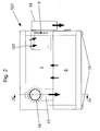
- FIG. 1 With 1 while a planing machine is referred to, which is parked on a designated 2 subframe and is set up with its work surface at the working height of an operator.
- the base 2 stands on rubber feet 10 and has a table top 8, on which in turn the planing machine 1 is parked with their feet 9.
- the undercarriage 2 is height and footprint matched to the dimensions of the planer 1 and comparable machines from a series of machines with approximately the same dimensions, making it universal for all Machines of this series, such as circular saws, planers, etc. can be used.
- the undercarriage 2 on a fan 5 and a drive unit 19 for the fan fan unit formed, 19, which is arranged at a serving as clean air outlet opening in a side wall of the undercarriage.
- the undercarriage 2 encloses a multi-sided chamber 3, which serves as a solid-state receiving volume for receiving the solids contained in the extracted air and separated therefrom.
- the chamber 3 is accessible for clearing via a removal opening (from the leaf level in the figure into the chamber inside).
- the removal opening is closed by a, for example, provided with circumferential rubber seals door, which in the FIG. 1 not shown.
- a filter 7 which covers the clean air outlet and the solids contained in the exhaust air, here, shavings, withholds.
- the filter 7 is formed in the illustrated embodiment as a planar cover of the fan and the clean air outlet and may for example be formed of an easy-to-clean material such as a foam or a filter fabric, which is arranged interchangeably in a corresponding holder or console.
- the drive unit 19 is supplied via an unillustrated power supply cable via the mains with electrical energy and has a slot, also not shown for the Power supply line of the machine 1, which is connected to the power supply of the drive unit 19. In the manner of a switchable connector strip, the drive unit can simultaneously be switched on via a switch and the slot for the machine 1 can be switched on.
- the fan 5 is actuated via an electric motor of the drive unit 19 and the planing machine 1 is simultaneously activated.
- the door is closed in front of the chamber 3
- exhaust air and planing chips and other impurities contained in it are sucked via the suction nozzle 14 and the suction hose 15 into the interior of the chamber 3 via the exhaust air inlet 4.
- Heavy solids fall there due to their weight down and are thus viewed from the exhaust air stream, which is sucked to the clean air outlet side, as shown by the branching arrow in the figure.
- the fan runs, for example, timer-controlled for a while after the machine is already switched off, so as to suck as possible all chips.
- FIG. 1 Another embodiment of the invention is the Figures 2-4 refer to.
- base 102 has the same cabinet-like structure as the base 2 of FIG. 1 on, wherein a chamber 3 formed as a sheet metal side walls 11, also designed as a sheet metal profile, welded thereon table top 8 and welded to the side walls 11 floor panel 12 is multi-sided and accessible via a closable with a door 13 removal opening.
- the door 13 and the facing her edges of the wall profiles 8, 11, 12th can be provided with seals, not shown.
- a dimensionally stable chip bag or filter container 6 is housed, which is matched in terms of dimension exactly on the base of the chamber 3 and height ranging just below a arranged in front of the fan 5 and the clean air outlet filter cartridge 7.
- the chip bag 6 is connected via a connection hose 17 to a hose connecting piece 16 functioning as an exhaust air inlet.
- the hose connection piece 16 protrudes both into the interior of the chamber to accommodate the connection hose 17, which is provided with suitable tensioning devices, such as e.g. a hose clamp can be attached to the connecting piece 16, as well as to the outside to receive there in the same way coming from the machine tool suction hose.
- the hose connection piece 16 further has a connection branch 18, to which an additional suction hose required for circular saws can be connected.
- the connection branch 18 and the main connection can each be closed in order to provide connection possibilities for suction hoses of different diameters.
- the filter cartridge 107 encloses the fan 5 with a cylindrical filter section and has a circular-plate-shaped cover, so that the air flow sucked towards the clean air outlet is led through the cylindrical filter section.
- the drive unit 19 for the fan 5 corresponds to the same construction as described in the previous embodiment and the clean air outlet channel is passed through the drive unit 19. If the fan 5 is actuated via the electric motor arranged in the drive unit 19, first exhaust air is sucked into the chip bag 6 via the exhaust air inlet 16 and the connection hose 17, which consists of a filter textile coarse-pored compared to the filter material of the dust filter cartridge 107, such as a polyester filter bag.
- Needlefelt consists, or has an outer shell of the filter fabric, wherein the connection hose 17 also may be made of a different material, such as a plastic, which may be glued at the junction in the outer shell with the outer shell.
- the chip bag 6 are thus coarser solids, ie z. As shavings or the like retained, whereas dusts with the exhaust air flow through the outer shell of the chip bag 6 and are deposited on the dust filter cartridge 107 from the exhaust stream and remain in the cylindrical filter material of the filter cartridge 107.
- the two-stage filtering can prevent clogging of the dust filter cartridge 107 so that it only very rarely needs to be replaced or cleaned, whereas the chip bag 6 can be more frequently removed and emptied via the removal opening of the chamber 3. Compared to an embodiment without chip bag here clearing easier, since the chip bag can be removed and emptied as a whole.
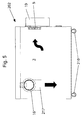
- FIG. 5 a further embodiment of the invention, in which no filter is installed at all, but only because of the height-wise distance of the clean air outlet from the bottom level of the chamber 3, a deposition of at least heavier and larger solids from the exhaust air flow takes place.
- This enters the inside of the chamber 3 of the undercarriage 202 via a suction hose of the machine tool attached to the hose connecting piece 16 and a downwardly curved inlet bend 217, where it is sucked towards the fan 5, whereby chips deposit on the bottom of the chamber 3 due to gravity , which in turn is accessible via a door, not shown.
- the base 202 also has rollers so that it is freely movable in the workshop.
- a filter arranged downstream of the drive unit 19 to be provided downstream of the air duct, which is accessible for cleaning or replacement purposes from the outside.
- a flap or a roll-up door could just as well be provided on the underframe.
- the chip bag could make only a single-stage filtration of the exhaust and the dust filter cartridge 7 omitted, so far a higher dust load acceptable or a narrow-pored filter textile is selected for the chip bag.
- a higher dust load acceptable or a narrow-pored filter textile is selected for the chip bag.
- this case also does not necessarily have a closed chamber 3 to be present. It is sufficient a filing or recording for the chip bag in an open base.
Landscapes
- Engineering & Computer Science (AREA)
- Mechanical Engineering (AREA)
- Chemical & Material Sciences (AREA)
- Chemical Kinetics & Catalysis (AREA)
- Filtering Of Dispersed Particles In Gases (AREA)
- Workshop Equipment, Work Benches, Supports, Or Storage Means (AREA)
- Preliminary Treatment Of Fibers (AREA)
Priority Applications (1)
| Application Number | Priority Date | Filing Date | Title |
|---|---|---|---|
| DE202010014520U DE202010014520U1 (de) | 2009-03-27 | 2010-02-18 | Untergestell für eine Werkzeugmaschine |
Applications Claiming Priority (1)
| Application Number | Priority Date | Filing Date | Title |
|---|---|---|---|
| DE102009014716A DE102009014716A1 (de) | 2009-03-27 | 2009-03-27 | Untergestell für eine Werkzeugmaschine |
Publications (2)
| Publication Number | Publication Date |
|---|---|
| EP2233242A1 true EP2233242A1 (fr) | 2010-09-29 |
| EP2233242B1 EP2233242B1 (fr) | 2011-09-21 |
Family
ID=42271848
Family Applications (1)
| Application Number | Title | Priority Date | Filing Date |
|---|---|---|---|
| EP10001637A Not-in-force EP2233242B1 (fr) | 2009-03-27 | 2010-02-18 | Châssis pour machine sur plateau de traitement du bois |
Country Status (3)
| Country | Link |
|---|---|
| EP (1) | EP2233242B1 (fr) |
| AT (1) | ATE525163T1 (fr) |
| DE (2) | DE102009014716A1 (fr) |
Cited By (2)
| Publication number | Priority date | Publication date | Assignee | Title |
|---|---|---|---|---|
| CN112008811A (zh) * | 2020-09-10 | 2020-12-01 | 天津市瑞福家具有限公司 | 一种用于定制家具板材加工的数控拉槽设备 |
| CN113635178A (zh) * | 2021-09-07 | 2021-11-12 | 钱华芳 | 一种胶合板表面精处理系统 |
Families Citing this family (1)
| Publication number | Priority date | Publication date | Assignee | Title |
|---|---|---|---|---|
| CN111975437A (zh) * | 2020-08-18 | 2020-11-24 | 陈绣定 | 一种防堵塞式精密仪器加工用机床防灰尘装置 |
Citations (4)
| Publication number | Priority date | Publication date | Assignee | Title |
|---|---|---|---|---|
| US3514906A (en) * | 1967-11-24 | 1970-06-02 | Everett Ind Inc | Cut-off machine |
| US4221081A (en) * | 1978-08-28 | 1980-09-09 | Everett Charles T | Dust collector system for belt sander |
| DE8814041U1 (de) * | 1987-11-23 | 1989-02-16 | Sagitta S.p.A., Vigevano, Pavia | Stützbett für Maschinen für Schuhfabriken, insbesondere für Leder-Abschrägmaschinen |
| EP0879671A2 (fr) * | 1997-05-22 | 1998-11-25 | Chiron-Werke GmbH & Co. KG | Machine-outil |
Family Cites Families (2)
| Publication number | Priority date | Publication date | Assignee | Title |
|---|---|---|---|---|
| US3514902A (en) | 1969-02-14 | 1970-06-02 | Orin M Anderson | Top door mechanism for top loading refuse vehicle |
| DE3202737A1 (de) * | 1982-01-28 | 1983-08-04 | Friedhelm 4992 Espelkamp Blotevogel | Bohrvorrichtung fuer decken o.dgl. |
-
2009
- 2009-03-27 DE DE102009014716A patent/DE102009014716A1/de not_active Withdrawn
-
2010
- 2010-02-18 AT AT10001637T patent/ATE525163T1/de active
- 2010-02-18 EP EP10001637A patent/EP2233242B1/fr not_active Not-in-force
- 2010-02-18 DE DE202010014520U patent/DE202010014520U1/de not_active Expired - Lifetime
Patent Citations (4)
| Publication number | Priority date | Publication date | Assignee | Title |
|---|---|---|---|---|
| US3514906A (en) * | 1967-11-24 | 1970-06-02 | Everett Ind Inc | Cut-off machine |
| US4221081A (en) * | 1978-08-28 | 1980-09-09 | Everett Charles T | Dust collector system for belt sander |
| DE8814041U1 (de) * | 1987-11-23 | 1989-02-16 | Sagitta S.p.A., Vigevano, Pavia | Stützbett für Maschinen für Schuhfabriken, insbesondere für Leder-Abschrägmaschinen |
| EP0879671A2 (fr) * | 1997-05-22 | 1998-11-25 | Chiron-Werke GmbH & Co. KG | Machine-outil |
Non-Patent Citations (2)
| Title |
|---|
| "IXES professional 2001", MASCHINENFABRIK GMBH & CO., pages: 32 - 33 |
| "Scheppach Werkstatt", February 2001, MASCHINENFABRIK GMBH & CO. |
Cited By (2)
| Publication number | Priority date | Publication date | Assignee | Title |
|---|---|---|---|---|
| CN112008811A (zh) * | 2020-09-10 | 2020-12-01 | 天津市瑞福家具有限公司 | 一种用于定制家具板材加工的数控拉槽设备 |
| CN113635178A (zh) * | 2021-09-07 | 2021-11-12 | 钱华芳 | 一种胶合板表面精处理系统 |
Also Published As
| Publication number | Publication date |
|---|---|
| DE102009014716A1 (de) | 2010-10-07 |
| ATE525163T1 (de) | 2011-10-15 |
| EP2233242B1 (fr) | 2011-09-21 |
| DE202010014520U1 (de) | 2011-01-05 |
Similar Documents
| Publication | Publication Date | Title |
|---|---|---|
| EP0155502B1 (fr) | Appareil de nettoyage pour piscines ou des choses pareilles | |
| DE10153939B4 (de) | Handwerkzeugmaschine mit Staubbehälter | |
| EP1427569A1 (fr) | Machine-outil a main avec dispositif d'aspiration de poussiere | |
| DE10254839A1 (de) | Handwerkzeugmaschine mit Staubbox | |
| WO2015091341A1 (fr) | Dispositif d'aspiration, machine-outil et procédé d'aspiration | |
| EP2233242B1 (fr) | Châssis pour machine sur plateau de traitement du bois | |
| DE102011003223A1 (de) | Verfahren und Einrichtung zum Entfernen von bei der Boden- oder Wandbearbeitung einer Fläche mittels eines motorischen Schleifwerkzeugs anfallenden Abtragpartikeln | |
| DE102016118806A1 (de) | Staubsauger sowie System aus einem Staubsauger und einer Basisstation | |
| DE102005020400A1 (de) | Einrichtung zum Filtern von extrem feinem Staub | |
| EP1878526A1 (fr) | Machine de traitement du bois | |
| DE102016123179A1 (de) | Werkzeugmaschine mit Staubsammelvorrichtung | |
| EP1429891A1 (fr) | Machine-outil dotee d'un compartiment a poussiere | |
| DE69400004T2 (de) | Vorrichtung zum Saugen und Speichern von Abfällen. | |
| EP0598246B1 (fr) | Lieu de travail avec une table de travail et une installation d'aspiration pourvue d'un dispositif de filtrage | |
| DE10209325B4 (de) | Elektrohandwerkzeug | |
| DE202005002979U1 (de) | Sauggerät | |
| DE29603771U1 (de) | Absaugeinrichtung | |
| DE202013100593U1 (de) | Vorrichtung zur Reinigung eines Rundfilters | |
| CN215618657U (zh) | 一种用于薄木板生产的夹紧切割装置 | |
| EP4245489B1 (fr) | Plaqueuse de chants | |
| DE3303534C2 (fr) | ||
| DE10047274A1 (de) | Vorsammler | |
| DE102006001738B3 (de) | Vorrichtung zum Sammeln von Folienverschnitt an Verpackungsmaschinen | |
| DE29710410U1 (de) | Absaugvorrichtung | |
| EP0509052B1 (fr) | Dispositif de nettoyage d'appareil mecaniques, de petites pieces et/ou d'unites de commutation electroniques |
Legal Events
| Date | Code | Title | Description |
|---|---|---|---|
| PUAI | Public reference made under article 153(3) epc to a published international application that has entered the european phase |
Free format text: ORIGINAL CODE: 0009012 |
|
| AK | Designated contracting states |
Kind code of ref document: A1 Designated state(s): AT BE BG CH CY CZ DE DK EE ES FI FR GB GR HR HU IE IS IT LI LT LU LV MC MK MT NL NO PL PT RO SE SI SK SM TR |
|
| AX | Request for extension of the european patent |
Extension state: AL BA RS |
|
| 17P | Request for examination filed |
Effective date: 20110329 |
|
| GRAP | Despatch of communication of intention to grant a patent |
Free format text: ORIGINAL CODE: EPIDOSNIGR1 |
|
| RIC1 | Information provided on ipc code assigned before grant |
Ipc: B23Q 11/00 20060101ALI20110506BHEP Ipc: B01D 50/00 20060101ALI20110506BHEP Ipc: B23Q 1/01 20060101AFI20110506BHEP |
|
| RTI1 | Title (correction) |
Free format text: SUBFRAME FOR A ON-TABLE WOOD PROCESSING MACHINE |
|
| GRAS | Grant fee paid |
Free format text: ORIGINAL CODE: EPIDOSNIGR3 |
|
| GRAA | (expected) grant |
Free format text: ORIGINAL CODE: 0009210 |
|
| AK | Designated contracting states |
Kind code of ref document: B1 Designated state(s): AT BE BG CH CY CZ DE DK EE ES FI FR GB GR HR HU IE IS IT LI LT LU LV MC MK MT NL NO PL PT RO SE SI SK SM TR |
|
| REG | Reference to a national code |
Ref country code: GB Ref legal event code: FG4D Free format text: NOT ENGLISH |
|
| REG | Reference to a national code |
Ref country code: CH Ref legal event code: EP |
|
| REG | Reference to a national code |
Ref country code: IE Ref legal event code: FG4D Free format text: LANGUAGE OF EP DOCUMENT: GERMAN |
|
| REG | Reference to a national code |
Ref country code: DE Ref legal event code: R096 Ref document number: 502010000112 Country of ref document: DE Effective date: 20111201 |
|
| REG | Reference to a national code |
Ref country code: NL Ref legal event code: VDEP Effective date: 20110921 |
|
| PG25 | Lapsed in a contracting state [announced via postgrant information from national office to epo] |
Ref country code: HR Free format text: LAPSE BECAUSE OF FAILURE TO SUBMIT A TRANSLATION OF THE DESCRIPTION OR TO PAY THE FEE WITHIN THE PRESCRIBED TIME-LIMIT Effective date: 20110921 Ref country code: LT Free format text: LAPSE BECAUSE OF FAILURE TO SUBMIT A TRANSLATION OF THE DESCRIPTION OR TO PAY THE FEE WITHIN THE PRESCRIBED TIME-LIMIT Effective date: 20110921 Ref country code: SE Free format text: LAPSE BECAUSE OF FAILURE TO SUBMIT A TRANSLATION OF THE DESCRIPTION OR TO PAY THE FEE WITHIN THE PRESCRIBED TIME-LIMIT Effective date: 20110921 Ref country code: FI Free format text: LAPSE BECAUSE OF FAILURE TO SUBMIT A TRANSLATION OF THE DESCRIPTION OR TO PAY THE FEE WITHIN THE PRESCRIBED TIME-LIMIT Effective date: 20110921 Ref country code: NO Free format text: LAPSE BECAUSE OF FAILURE TO SUBMIT A TRANSLATION OF THE DESCRIPTION OR TO PAY THE FEE WITHIN THE PRESCRIBED TIME-LIMIT Effective date: 20111221 |
|
| LTIE | Lt: invalidation of european patent or patent extension |
Effective date: 20110921 |
|
| PG25 | Lapsed in a contracting state [announced via postgrant information from national office to epo] |
Ref country code: GR Free format text: LAPSE BECAUSE OF FAILURE TO SUBMIT A TRANSLATION OF THE DESCRIPTION OR TO PAY THE FEE WITHIN THE PRESCRIBED TIME-LIMIT Effective date: 20111222 Ref country code: CY Free format text: LAPSE BECAUSE OF FAILURE TO SUBMIT A TRANSLATION OF THE DESCRIPTION OR TO PAY THE FEE WITHIN THE PRESCRIBED TIME-LIMIT Effective date: 20110921 Ref country code: LV Free format text: LAPSE BECAUSE OF FAILURE TO SUBMIT A TRANSLATION OF THE DESCRIPTION OR TO PAY THE FEE WITHIN THE PRESCRIBED TIME-LIMIT Effective date: 20110921 Ref country code: SI Free format text: LAPSE BECAUSE OF FAILURE TO SUBMIT A TRANSLATION OF THE DESCRIPTION OR TO PAY THE FEE WITHIN THE PRESCRIBED TIME-LIMIT Effective date: 20110921 |
|
| REG | Reference to a national code |
Ref country code: IE Ref legal event code: FD4D |
|
| PG25 | Lapsed in a contracting state [announced via postgrant information from national office to epo] |
Ref country code: CZ Free format text: LAPSE BECAUSE OF FAILURE TO SUBMIT A TRANSLATION OF THE DESCRIPTION OR TO PAY THE FEE WITHIN THE PRESCRIBED TIME-LIMIT Effective date: 20110921 Ref country code: SK Free format text: LAPSE BECAUSE OF FAILURE TO SUBMIT A TRANSLATION OF THE DESCRIPTION OR TO PAY THE FEE WITHIN THE PRESCRIBED TIME-LIMIT Effective date: 20110921 Ref country code: IE Free format text: LAPSE BECAUSE OF FAILURE TO SUBMIT A TRANSLATION OF THE DESCRIPTION OR TO PAY THE FEE WITHIN THE PRESCRIBED TIME-LIMIT Effective date: 20110921 Ref country code: IS Free format text: LAPSE BECAUSE OF FAILURE TO SUBMIT A TRANSLATION OF THE DESCRIPTION OR TO PAY THE FEE WITHIN THE PRESCRIBED TIME-LIMIT Effective date: 20120121 |
|
| PG25 | Lapsed in a contracting state [announced via postgrant information from national office to epo] |
Ref country code: RO Free format text: LAPSE BECAUSE OF FAILURE TO SUBMIT A TRANSLATION OF THE DESCRIPTION OR TO PAY THE FEE WITHIN THE PRESCRIBED TIME-LIMIT Effective date: 20110921 Ref country code: EE Free format text: LAPSE BECAUSE OF FAILURE TO SUBMIT A TRANSLATION OF THE DESCRIPTION OR TO PAY THE FEE WITHIN THE PRESCRIBED TIME-LIMIT Effective date: 20110921 Ref country code: PT Free format text: LAPSE BECAUSE OF FAILURE TO SUBMIT A TRANSLATION OF THE DESCRIPTION OR TO PAY THE FEE WITHIN THE PRESCRIBED TIME-LIMIT Effective date: 20120123 Ref country code: NL Free format text: LAPSE BECAUSE OF FAILURE TO SUBMIT A TRANSLATION OF THE DESCRIPTION OR TO PAY THE FEE WITHIN THE PRESCRIBED TIME-LIMIT Effective date: 20110921 Ref country code: PL Free format text: LAPSE BECAUSE OF FAILURE TO SUBMIT A TRANSLATION OF THE DESCRIPTION OR TO PAY THE FEE WITHIN THE PRESCRIBED TIME-LIMIT Effective date: 20110921 Ref country code: IT Free format text: LAPSE BECAUSE OF FAILURE TO SUBMIT A TRANSLATION OF THE DESCRIPTION OR TO PAY THE FEE WITHIN THE PRESCRIBED TIME-LIMIT Effective date: 20110921 |
|
| PLBE | No opposition filed within time limit |
Free format text: ORIGINAL CODE: 0009261 |
|
| STAA | Information on the status of an ep patent application or granted ep patent |
Free format text: STATUS: NO OPPOSITION FILED WITHIN TIME LIMIT |
|
| PG25 | Lapsed in a contracting state [announced via postgrant information from national office to epo] |
Ref country code: DK Free format text: LAPSE BECAUSE OF FAILURE TO SUBMIT A TRANSLATION OF THE DESCRIPTION OR TO PAY THE FEE WITHIN THE PRESCRIBED TIME-LIMIT Effective date: 20110921 |
|
| 26N | No opposition filed |
Effective date: 20120622 |
|
| BERE | Be: lapsed |
Owner name: SCHEPPACH FABRIKATION VON HOLZBEARBEITUNGSMASCHIN Effective date: 20120228 |
|
| PG25 | Lapsed in a contracting state [announced via postgrant information from national office to epo] |
Ref country code: MC Free format text: LAPSE BECAUSE OF NON-PAYMENT OF DUE FEES Effective date: 20120229 |
|
| REG | Reference to a national code |
Ref country code: DE Ref legal event code: R097 Ref document number: 502010000112 Country of ref document: DE Effective date: 20120622 |
|
| PG25 | Lapsed in a contracting state [announced via postgrant information from national office to epo] |
Ref country code: BE Free format text: LAPSE BECAUSE OF NON-PAYMENT OF DUE FEES Effective date: 20120228 |
|
| PG25 | Lapsed in a contracting state [announced via postgrant information from national office to epo] |
Ref country code: MK Free format text: LAPSE BECAUSE OF FAILURE TO SUBMIT A TRANSLATION OF THE DESCRIPTION OR TO PAY THE FEE WITHIN THE PRESCRIBED TIME-LIMIT Effective date: 20110921 |
|
| PG25 | Lapsed in a contracting state [announced via postgrant information from national office to epo] |
Ref country code: ES Free format text: LAPSE BECAUSE OF FAILURE TO SUBMIT A TRANSLATION OF THE DESCRIPTION OR TO PAY THE FEE WITHIN THE PRESCRIBED TIME-LIMIT Effective date: 20120101 |
|
| PG25 | Lapsed in a contracting state [announced via postgrant information from national office to epo] |
Ref country code: BG Free format text: LAPSE BECAUSE OF FAILURE TO SUBMIT A TRANSLATION OF THE DESCRIPTION OR TO PAY THE FEE WITHIN THE PRESCRIBED TIME-LIMIT Effective date: 20111221 |
|
| PG25 | Lapsed in a contracting state [announced via postgrant information from national office to epo] |
Ref country code: MT Free format text: LAPSE BECAUSE OF FAILURE TO SUBMIT A TRANSLATION OF THE DESCRIPTION OR TO PAY THE FEE WITHIN THE PRESCRIBED TIME-LIMIT Effective date: 20110921 |
|
| PG25 | Lapsed in a contracting state [announced via postgrant information from national office to epo] |
Ref country code: TR Free format text: LAPSE BECAUSE OF FAILURE TO SUBMIT A TRANSLATION OF THE DESCRIPTION OR TO PAY THE FEE WITHIN THE PRESCRIBED TIME-LIMIT Effective date: 20110921 |
|
| PG25 | Lapsed in a contracting state [announced via postgrant information from national office to epo] |
Ref country code: SM Free format text: LAPSE BECAUSE OF FAILURE TO SUBMIT A TRANSLATION OF THE DESCRIPTION OR TO PAY THE FEE WITHIN THE PRESCRIBED TIME-LIMIT Effective date: 20110921 Ref country code: LU Free format text: LAPSE BECAUSE OF NON-PAYMENT OF DUE FEES Effective date: 20120218 |
|
| PG25 | Lapsed in a contracting state [announced via postgrant information from national office to epo] |
Ref country code: HU Free format text: LAPSE BECAUSE OF FAILURE TO SUBMIT A TRANSLATION OF THE DESCRIPTION OR TO PAY THE FEE WITHIN THE PRESCRIBED TIME-LIMIT Effective date: 20100218 |
|
| REG | Reference to a national code |
Ref country code: CH Ref legal event code: PL |
|
| GBPC | Gb: european patent ceased through non-payment of renewal fee |
Effective date: 20140218 |
|
| PG25 | Lapsed in a contracting state [announced via postgrant information from national office to epo] |
Ref country code: LI Free format text: LAPSE BECAUSE OF NON-PAYMENT OF DUE FEES Effective date: 20140228 Ref country code: CH Free format text: LAPSE BECAUSE OF NON-PAYMENT OF DUE FEES Effective date: 20140228 |
|
| PG25 | Lapsed in a contracting state [announced via postgrant information from national office to epo] |
Ref country code: GB Free format text: LAPSE BECAUSE OF NON-PAYMENT OF DUE FEES Effective date: 20140218 |
|
| REG | Reference to a national code |
Ref country code: FR Ref legal event code: PLFP Year of fee payment: 6 |
|
| PGFP | Annual fee paid to national office [announced via postgrant information from national office to epo] |
Ref country code: DE Payment date: 20150228 Year of fee payment: 6 |
|
| PGFP | Annual fee paid to national office [announced via postgrant information from national office to epo] |
Ref country code: FR Payment date: 20150217 Year of fee payment: 6 |
|
| REG | Reference to a national code |
Ref country code: AT Ref legal event code: MM01 Ref document number: 525163 Country of ref document: AT Kind code of ref document: T Effective date: 20150218 |
|
| PG25 | Lapsed in a contracting state [announced via postgrant information from national office to epo] |
Ref country code: AT Free format text: LAPSE BECAUSE OF NON-PAYMENT OF DUE FEES Effective date: 20150218 |
|
| REG | Reference to a national code |
Ref country code: DE Ref legal event code: R119 Ref document number: 502010000112 Country of ref document: DE |
|
| REG | Reference to a national code |
Ref country code: FR Ref legal event code: ST Effective date: 20161028 |
|
| PG25 | Lapsed in a contracting state [announced via postgrant information from national office to epo] |
Ref country code: FR Free format text: LAPSE BECAUSE OF NON-PAYMENT OF DUE FEES Effective date: 20160229 Ref country code: DE Free format text: LAPSE BECAUSE OF NON-PAYMENT OF DUE FEES Effective date: 20160901 |