EP2233242B1 - Châssis pour machine sur plateau de traitement du bois - Google Patents
Châssis pour machine sur plateau de traitement du bois Download PDFInfo
- Publication number
- EP2233242B1 EP2233242B1 EP10001637A EP10001637A EP2233242B1 EP 2233242 B1 EP2233242 B1 EP 2233242B1 EP 10001637 A EP10001637 A EP 10001637A EP 10001637 A EP10001637 A EP 10001637A EP 2233242 B1 EP2233242 B1 EP 2233242B1
- Authority
- EP
- European Patent Office
- Prior art keywords
- chamber
- exhaust air
- subframe
- filter
- woodworking machine
- Prior art date
- Legal status (The legal status is an assumption and is not a legal conclusion. Google has not performed a legal analysis and makes no representation as to the accuracy of the status listed.)
- Not-in-force
Links
- 239000002023 wood Substances 0.000 title 1
- 239000007787 solid Substances 0.000 claims abstract description 22
- 238000000926 separation method Methods 0.000 claims abstract description 7
- 238000000605 extraction Methods 0.000 claims description 17
- 239000000428 dust Substances 0.000 claims description 11
- 239000000463 material Substances 0.000 claims description 11
- 239000004753 textile Substances 0.000 claims description 5
- 229920000728 polyester Polymers 0.000 claims description 3
- 238000011144 upstream manufacturing Methods 0.000 claims 3
- 238000000151 deposition Methods 0.000 claims 1
- 238000007599 discharging Methods 0.000 claims 1
- 230000004308 accommodation Effects 0.000 abstract 2
- 238000001914 filtration Methods 0.000 description 3
- 239000002184 metal Substances 0.000 description 3
- 230000007797 corrosion Effects 0.000 description 2
- 238000005260 corrosion Methods 0.000 description 2
- 239000004744 fabric Substances 0.000 description 2
- 239000012535 impurity Substances 0.000 description 2
- 238000004140 cleaning Methods 0.000 description 1
- 238000010276 construction Methods 0.000 description 1
- 239000000356 contaminant Substances 0.000 description 1
- 230000008021 deposition Effects 0.000 description 1
- 230000003670 easy-to-clean Effects 0.000 description 1
- 239000006260 foam Substances 0.000 description 1
- 230000005484 gravity Effects 0.000 description 1
- 238000012986 modification Methods 0.000 description 1
- 230000004048 modification Effects 0.000 description 1
- 239000004033 plastic Substances 0.000 description 1
- 230000009467 reduction Effects 0.000 description 1
- 230000000717 retained effect Effects 0.000 description 1
Images


Classifications
-
- B—PERFORMING OPERATIONS; TRANSPORTING
- B23—MACHINE TOOLS; METAL-WORKING NOT OTHERWISE PROVIDED FOR
- B23Q—DETAILS, COMPONENTS, OR ACCESSORIES FOR MACHINE TOOLS, e.g. ARRANGEMENTS FOR COPYING OR CONTROLLING; MACHINE TOOLS IN GENERAL CHARACTERISED BY THE CONSTRUCTION OF PARTICULAR DETAILS OR COMPONENTS; COMBINATIONS OR ASSOCIATIONS OF METAL-WORKING MACHINES, NOT DIRECTED TO A PARTICULAR RESULT
- B23Q11/00—Accessories fitted to machine tools for keeping tools or parts of the machine in good working condition or for cooling work; Safety devices specially combined with or arranged in, or specially adapted for use in connection with, machine tools
- B23Q11/0042—Devices for removing chips
- B23Q11/0046—Devices for removing chips by sucking
-
- B—PERFORMING OPERATIONS; TRANSPORTING
- B01—PHYSICAL OR CHEMICAL PROCESSES OR APPARATUS IN GENERAL
- B01D—SEPARATION
- B01D50/00—Combinations of methods or devices for separating particles from gases or vapours
- B01D50/20—Combinations of devices covered by groups B01D45/00 and B01D46/00
-
- B—PERFORMING OPERATIONS; TRANSPORTING
- B23—MACHINE TOOLS; METAL-WORKING NOT OTHERWISE PROVIDED FOR
- B23Q—DETAILS, COMPONENTS, OR ACCESSORIES FOR MACHINE TOOLS, e.g. ARRANGEMENTS FOR COPYING OR CONTROLLING; MACHINE TOOLS IN GENERAL CHARACTERISED BY THE CONSTRUCTION OF PARTICULAR DETAILS OR COMPONENTS; COMBINATIONS OR ASSOCIATIONS OF METAL-WORKING MACHINES, NOT DIRECTED TO A PARTICULAR RESULT
- B23Q1/00—Members which are comprised in the general build-up of a form of machine, particularly relatively large fixed members
- B23Q1/01—Frames, beds, pillars or like members; Arrangement of ways
- B23Q1/015—Frames, beds, pillars
-
- B—PERFORMING OPERATIONS; TRANSPORTING
- B23—MACHINE TOOLS; METAL-WORKING NOT OTHERWISE PROVIDED FOR
- B23Q—DETAILS, COMPONENTS, OR ACCESSORIES FOR MACHINE TOOLS, e.g. ARRANGEMENTS FOR COPYING OR CONTROLLING; MACHINE TOOLS IN GENERAL CHARACTERISED BY THE CONSTRUCTION OF PARTICULAR DETAILS OR COMPONENTS; COMBINATIONS OR ASSOCIATIONS OF METAL-WORKING MACHINES, NOT DIRECTED TO A PARTICULAR RESULT
- B23Q11/00—Accessories fitted to machine tools for keeping tools or parts of the machine in good working condition or for cooling work; Safety devices specially combined with or arranged in, or specially adapted for use in connection with, machine tools
- B23Q11/0042—Devices for removing chips
- B23Q11/0053—Devices for removing chips using the gravity force
-
- B—PERFORMING OPERATIONS; TRANSPORTING
- B23—MACHINE TOOLS; METAL-WORKING NOT OTHERWISE PROVIDED FOR
- B23Q—DETAILS, COMPONENTS, OR ACCESSORIES FOR MACHINE TOOLS, e.g. ARRANGEMENTS FOR COPYING OR CONTROLLING; MACHINE TOOLS IN GENERAL CHARACTERISED BY THE CONSTRUCTION OF PARTICULAR DETAILS OR COMPONENTS; COMBINATIONS OR ASSOCIATIONS OF METAL-WORKING MACHINES, NOT DIRECTED TO A PARTICULAR RESULT
- B23Q11/00—Accessories fitted to machine tools for keeping tools or parts of the machine in good working condition or for cooling work; Safety devices specially combined with or arranged in, or specially adapted for use in connection with, machine tools
- B23Q11/0042—Devices for removing chips
- B23Q11/0067—Devices for removing chips chip containers located under a machine or under a chip conveyor
Definitions
- the invention relates to a subframe for a baseless Auftischholzbearbeitungsmaschine according to the preamble of claim 1.
- this subframe has two exhaust air inlets for the exhaust air coming from the grinding wheels and a fan arrangement for exhausting the exhaust air.
- the exhaust air can escape through provided on the bottom openings from the base.
- a separation device for separating the grinding chips from the exhaust air is not provided.
- This known arrangement therefore does not prove safe and work-enough. Apart from this, this known arrangement is only suitable for machine tools with low chips and would lead to disturbances at high chips. The known arrangement is therefore only of limited use.
- a subframe which is suitable for setting up at least one baseless, wood-cutting table-top processing machine at working height of an operator, such as a circular saw, wherein the subframe is designed as a suction system for the machine tool, with at least one exhaust air inlet for coming from the machine tool exhaust air, a Fan arrangement for conveying the exhaust air stream, a separation arrangement for the separation of solids from the exhaust air stream, and a solid-body receiving volume for receiving the separated from the exhaust air solids, and a clean air outlet, to the the cleaned exhaust air flow is conveyed by the fan assembly, wherein the lower frame has a multi-sidedly enclosed by its walls chamber which is closed by a door and accessible for clearing, the exhaust air inlet opens into the chamber and the clean air outlet leads out of the chamber, so that the Chamber can serve as a solid body volume.
- underframe extraction module With the underframe extraction module according to the invention, a universally applicable extraction system with a Abscheidean Aunt is created in a space-saving manner, which is stowed under the machine and at the same time takes over the function of the machine base, namely to bring the working level of the machine tool to working height of an operator.
- the base has for this purpose a cabinet-like, from its walls on several sides enclosed chamber, which is closed by a door.
- the chamber can thus serve as a solid-receiving volume when the exhaust air inlet opens into the chamber and a leading out of the chamber clean air outlet opening is provided. Over the door, the chamber can be cleared.
- the chamber can serve directly as a holding volume for the separated from the exhaust air solids, namely chips and / or dusts, with a large chip volume can be accommodated.
- a corresponding filter as Abscheidean ever be provided in front of the clean air outlet opening.
- the door of the chamber is provided with seals and the chamber walls also connect airtight to each other, for example, are welded.
- the clean air outlet opening can be arranged above and spaced from a floor level of the chamber, so that solids residues contained in the exhaust air are no longer carried out of the chamber through the clean air outlet opening due to their weight Chamber be caught.
- a filter container is housed in a closed chamber, which at least partially consists of an air-permeable but solid-retaining material and is connected to an inlet opening with the exhaust air inlet of the chamber.
- a closed chamber which at least partially consists of an air-permeable but solid-retaining material and is connected to an inlet opening with the exhaust air inlet of the chamber.
- a two-stage filtering can be realized.
- the filter container can be followed by another filter at the clean air outlet.
- the filter container could be designed as a chip bag made of a relatively coarse-meshed or coarse-pored textile, which retains coarser air contaminants, such as chips, but a dust laden with fine dust lets through, which is then cleaned in a mounted before the clean air outlet on a chamber wall filter cartridge from the fine dust.
- the chip bag can be easily accessed via the closed with the door removal opening of the chamber for emptying, whereas the filter cartridge, which is only achieved by the pre-filtered by the chip bag exhaust air flow, only rarely needs to be replaced.
- the fan unit may have a fan, which is preferably arranged on the clean air outlet and thus sucks the exhaust air stream, starting from the machine through the underframe extraction module without being exposed to corrosion due to entrained in the air flow foreign body. If the exhaust air flow is directed through a filter cartridge arranged in front of the clean air outlet, the fan of the filter cartridge is advantageously downstream in terms of flow so as to protect the fan unit against corrosion by dusts or the like present in the air stream and, on the other hand, to ensure easy accessibility from the outside.
- the fan unit may have a drive unit arranged on the outside of a chamber side wall, with which the fan can be driven. Such a drive unit, for example, have an electric motor with corresponding power supply lines for plugging into the power grid.
- the drive unit has a line leading to a slot for the machine to be set up on the undercarriage.
- an additional slot for the machine to be installed is provided on the drive unit, not only succeeds in reducing the amount to be laid Cable, but it can also be a circuit of the machine and the exhaust system realized by a common control unit, which is advantageously also integrated in the drive unit.
- a common control unit which is advantageously also integrated in the drive unit.
- a common switch may be provided on the drive unit, which switches the slot for the supply line of the machine and - with a time delay - the electric motor of the fan unit.
- a sensor which detects whether the machine is running or not and in response to the actuation of an on-off switch on the machine, the exhaust system on or off.
- the subframe is tailored to the size of particular machines for which it is intended to fit the size of a machine from a selection of similarly dimensioned machines or to different machines of one series, all of which have approximately the same dimension.
- the base frame on a table top which is suitable for common, for parking on a surface suitable Auftischholzbearbeitungsmaschinen.
- a handyman can thus be provided with a universally applicable underframe extraction module for his entire tabletop processing machine park.
- the invention is not limited thereto.
- FIG. 1 With 1 while a planing machine is referred to, which is parked on a designated 2 subframe and is set up with its work surface at the working height of an operator.
- the base 2 stands on rubber feet 10 and has a table top 8, on which in turn the planing machine 1 is parked with their feet 9.
- the undercarriage 2 is height and footprint matched to the dimensions of the planer 1 and similar machines from a series of machines with approximately the same dimensions, making it universal for all Machines of this series, such as circular saws, planers, etc. can be used.
- the undercarriage 2 on a fan 5 and a drive unit 19 for the fan fan unit formed, 19, which is arranged on a serving as a clean air outlet opening in a side wall of the undercarriage.
- the undercarriage 2 encloses a multi-sided chamber 3, which serves as a solid-state receiving volume for receiving the solids contained in the extracted air and separated therefrom.
- the chamber 3 is accessible for clearing via a removal opening (from the leaf level in the figure into the chamber inside).
- the removal opening is closed by a, for example, provided with circumferential rubber seals door, which in the FIG. 1 not shown.
- a filter 7 which covers the clean air outlet and the solids contained in the exhaust air, here, shavings, withholds.
- the filter 7 is formed in the illustrated embodiment as a planar cover of the fan and the clean air outlet and may for example be formed of an easy-to-clean material such as a foam or a filter fabric, which is arranged interchangeably in a corresponding holder or console.
- the drive unit 19 is supplied via an unillustrated power supply cable via the mains with electrical energy and has a slot, also not shown for the Power supply line of the machine 1, which is connected to the power supply of the drive unit 19. In the manner of a switchable connector strip, the drive unit can simultaneously be switched on via a switch and the slot for the machine 1 can be switched on.
- the fan 5 is actuated via an electric motor of the drive unit 19 and the planing machine 1 is simultaneously activated.
- the door is closed in front of the chamber 3
- exhaust air and planing chips and other impurities contained in it are sucked via the suction nozzle 14 and the suction hose 15 into the interior of the chamber 3 via the exhaust air inlet 4.
- Heavy solids fall there due to their weight down and are thus viewed from the exhaust air stream, which is sucked to the clean air outlet side, as shown by the branching arrow in the figure.
- the fan runs, for example, timer-controlled for a while, after the machine is already turned off, so as to suck as possible all the chips.
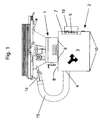
- FIG. 1 Another embodiment of the invention is the Figures 2-4 refer to.
- base 102 has the same cabinet-like structure as the base 2 of FIG. 1 on, wherein a chamber 3 formed as a sheet metal side walls 11, also designed as a sheet metal profile, welded thereon table top 8 and welded to the side walls 11 floor panel 12 is multi-sided and accessible via a closable with a door 13 removal opening.
- the door 13 and the facing her edges of the wall profiles 8, 11, 12th can be provided with seals, not shown.
- a dimensionally stable chip bag or filter container 6 is housed, which is matched in terms of dimension exactly on the base of the chamber 3 and height ranging just below a arranged in front of the fan 5 and the clean air outlet filter cartridge 7.
- the chip bag 6 is connected via a connection hose 17 to a hose connecting piece 16 functioning as an exhaust air inlet.
- the hose connection piece 16 protrudes both into the interior of the chamber to accommodate the connection hose 17, which is provided with suitable tensioning devices, such as e.g. a hose clamp can be attached to the connecting piece 16, as well as to the outside to receive there in the same way coming from the machine tool suction hose.
- the hose connection piece 16 further has a connection branch 18, to which an additional suction hose required for circular saws can be connected.
- the connection branch 18 and the main connection can each be closed in order to provide connection possibilities for suction hoses of different diameters.
- the filter cartridge 107 encloses the fan 5 with a cylindrical filter section and has a circular-plate-shaped cover, so that the air flow sucked towards the clean air outlet is led through the cylindrical filter section.
- the drive unit 19 for the fan 5 corresponds to the same construction as described in the previous embodiment and the clean air outlet channel is passed through the drive unit 19. If the fan 5 is actuated via the electric motor arranged in the drive unit 19, first exhaust air is sucked into the chip bag 6 via the exhaust air inlet 16 and the connection hose 17, which consists of a filter textile coarse-pored compared to the filter material of the dust filter cartridge 107, such as a polyester filter bag.
- Needlefelt consists, or has an outer shell of the filter fabric, wherein the connection hose 17 also may be made of a different material, such as a plastic, which may be glued at the junction in the outer shell with the outer shell.
- the chip bag 6 are thus coarser solids, ie z. As shavings or the like retained, whereas dusts with the exhaust air flow through the outer shell of the chip bag 6 and are deposited on the dust filter cartridge 107 from the exhaust stream and remain in the cylindrical filter material of the filter cartridge 107.
- the two-stage filtering can prevent clogging of the dust filter cartridge 107 so that it only very rarely needs to be replaced or cleaned, whereas the chip bag 6 can be more frequently removed and emptied via the removal opening of the chamber 3. Compared to an embodiment without chip bag here clearing easier, since the chip bag can be removed and emptied as a whole.
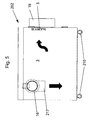
- FIG. 5 a further embodiment of the invention, in which no filter is installed at all, but only because of the height-wise distance of the clean air outlet from the bottom level of the chamber 3, a deposition of at least heavier and larger solids from the exhaust air flow takes place.
- This enters the inside of the chamber 3 of the undercarriage 202 via a suction hose of the machine tool attached to the hose connecting piece 16 and a downwardly curved inlet bend 217, where it is sucked towards the fan 5, whereby chips deposit on the bottom of the chamber 3 due to gravity , which in turn is accessible via a door, not shown.
- the base 202 also has rollers so that it is freely movable in the workshop.
- a filter arranged downstream of the drive unit 19 to be provided downstream of the air duct, which is accessible for cleaning or replacement purposes from the outside.
Landscapes
- Engineering & Computer Science (AREA)
- Mechanical Engineering (AREA)
- Chemical & Material Sciences (AREA)
- Chemical Kinetics & Catalysis (AREA)
- Filtering Of Dispersed Particles In Gases (AREA)
- Workshop Equipment, Work Benches, Supports, Or Storage Means (AREA)
- Preliminary Treatment Of Fibers (AREA)
Claims (12)
- Structure de support pour une machine de traitement du bois sur table (2 ; 102 ; 202) pour l'installation d'une machine de traitement du bois sur table (1) par usinage, sans socle, à la hauteur de travail d'un utilisateur, avec un plateau de table (8) dimensionné de façon appropriée pour des machines de traitement du bois sur table courantes, adaptées pour être posées sur une surface, telles que par exemple des scies circulaires ou des machines de dressage et d'usinage d'épaisseur, pour la disposition sur une machine de traitement du bois sur table, dans laquelle
la structure de support (2) est conçue comme un dispositif d'aspiration pour la machine-outil (1), avec au moins une entrée d'air sortant (4 ; 16, 17 ; 16, 217) pour de l'air sortant de la machine-outil (1), et un système de ventilateur (5, 19) pour le déplacement du flux d'air sortant, un système de séparation (3, 7 ; 6, 107 ; 3, 4, 19) pour l'évacuation de corps solides à partir du flux d'air sortant, un volume d'accueil de corps solides (3 ; 6, 7) pour la réception des corps solides extraits de l'air sortant, et une sortie d'air pur (19), vers laquelle est transporté le flux d'air purifié venant du système de ventilateur (5, 19),
caractérisée en ce que
la structure de support (2) comporte une chambre (3) entourée de plusieurs côtés de parois (8, 11, 12) reliées entre elles de façon quasiment hermétique, qui peut être fermée par une porte pourvue de joints d'étanchéité et qui est accessible pour l'évacuation, l'entrée d'air sortant (4 ; 16, 17 ; 16, 217) débouche dans la chambre (3), la sortie d'air pur (19) mène hors de la chambre (3), et le volume d'accueil de corps solides (3 ; 6) se trouve dans la chambre (3), et en ce que
à l'entrée d'air sortant (4 ; 16, 17 ; 16, 217), sur une paroi latérale de la chambre (3), il est prévu au moins un raccord de tuyau (16) pour un tuyau d'aspiration (15) permettant d'évacuer l'air sortant de la machine de traitement du bois sur table (1). - Structure de support pour une machine de traitement du bois sur table (2 ; 102 ; 202) selon la revendication 1, dans laquelle la sortie d'air pur (19) et de préférence également l'entrée d'air sortant (16, 217) débouchent au-dessus d'un plancher de chambre (12) dans la chambre (3), tout en étant espacées de celui-ci dans la hauteur.
- Structure de support pour une machine de traitement du bois sur table (102) selon l'une des revendications précédentes, dans laquelle le volume d'accueil de corps solides (6) se trouve dans un récipient de filtration (6) comportant une enveloppe extérieure constituée au moins partiellement d'un matériau filtrant et reliée à l'entrée d'air sortant (16, 17) par une ouverture d'entrée, dans laquelle le récipient de filtration (6) est installé dans la chambre (3).
- Structure de support pour une machine de traitement du bois sur table (102) selon la revendication 3, dans laquelle le matériau de filtration est de préférence une matière textile rigide, par exemple un feutre de polyester aiguilleté, et le récipient de filtration (6) est de préférence une poche à copeaux (6) constituée au moins en majeure partie de la matière textile.
- Structure de support pour une machine de traitement du bois sur table (2 ; 102) selon l'une des revendications précédentes, dans laquelle le système de séparation (3, 7 ; 6, 107) comporte une unité de filtration (7 ; 107) disposée en amont de la sortie d'air pur (19), par laquelle le flux d'air sortant est guidé hors de la chambre (3), en particulier une cartouche de filtration (107) disposée en amont de l'unité de ventilateur (5, 19) dans le sens du flux.
- Structure de support pour une machine de traitement du bois sur table (102) selon la revendication 5, dans laquelle le système de séparation (6, 107) dans la chambre (3) comporte le récipient de filtration (6) ainsi qu'une cartouche de filtration (107) disposée en aval du récipient de filtration (6) dans le sens du flux, dans laquelle la matière filtrante de l'enveloppe extérieure du récipient de filtration (6) laisse passer l'air, mais tout en retenant les copeaux, et la cartouche de filtration laisse passer l'air, mais tout en retenant la poussière, de sorte que le récipient de filtration (6) enserre un premier volume d'accueil de corps solides (6), destiné à des corps solides grossiers tels que des copeaux, et la cartouche de filtration (107) forme un deuxième volume d'accueil de corps solides (107) destiné à des corps solides plus fins, tels que la poussière.
- Structure de support pour une machine de traitement du bois sur table (2 ; 102; 202) selon l'une des revendications précédentes, dans laquelle le plateau de table (8) forme simultanément une paroi de la chambre (3).
- Structure de support pour une machine de traitement du bois sur table (102) selon la revendication 4, dans laquelle le raccord de tuyau (16) destiné à un tuyau d'aspiration (15) permettant d'évacuer l'air sortant de la machine (1) fait saillie vers l'extérieur à partir de la paroi latérale de la chambre (3), et s'introduit à l'intérieur de la chambre pour un tuyau de raccordement (17) débouchant dans la poche à copeaux (6).
- Structure de support pour une machine de traitement du bois sur table (2 ; 102 ; 202) selon l'une des revendications précédentes, dans laquelle le système de ventilateurs (5, 19) comporte un agrégat d'entraînement (19) disposé sur une paroi latérale (11) de la chambre, pour un ventilateur (5) disposé avant l'ouverture de sortie d'air pur dans la paroi latérale (11) de la chambre.
- Structure de support pour une machine de traitement du bois sur table (2 ; 102 ; 202) selon la revendication 9, dans laquelle l'agrégat d'entraînement (19) comporte au moins un point d'enfichage pour le branchement d'une alimentation électrique de la machine-outil (1), et de préférence un interrupteur MARCHE-ARRÊT, ainsi qu'une unité de commande permettant d'éteindre tout d'abord la machine-outil, par l'interrupteur MARCHE-ARRÊT, lors de l'extinction du dispositif d'aspiration et de l'alimentation électrique branchée sur l'agrégat d'entraînement, et d'éteindre ensuite le dispositif d'aspiration.
- Structure de support pour une machine de traitement du bois sur table (102) selon l'une des revendications 9 ou 10, dans laquelle la cartouche de filtration (107) comporte une section de filtration cylindrique encerclant le ventilateur (5), à travers laquelle passe le flux d'air sortant.
- Structure de support pour une machine de traitement du bois sur table (202) selon l'une des revendications précédentes, dans laquelle elle est disposée sur des roulettes (210).
Priority Applications (1)
| Application Number | Priority Date | Filing Date | Title |
|---|---|---|---|
| DE202010014520U DE202010014520U1 (de) | 2009-03-27 | 2010-02-18 | Untergestell für eine Werkzeugmaschine |
Applications Claiming Priority (1)
| Application Number | Priority Date | Filing Date | Title |
|---|---|---|---|
| DE102009014716A DE102009014716A1 (de) | 2009-03-27 | 2009-03-27 | Untergestell für eine Werkzeugmaschine |
Publications (2)
| Publication Number | Publication Date |
|---|---|
| EP2233242A1 EP2233242A1 (fr) | 2010-09-29 |
| EP2233242B1 true EP2233242B1 (fr) | 2011-09-21 |
Family
ID=42271848
Family Applications (1)
| Application Number | Title | Priority Date | Filing Date |
|---|---|---|---|
| EP10001637A Not-in-force EP2233242B1 (fr) | 2009-03-27 | 2010-02-18 | Châssis pour machine sur plateau de traitement du bois |
Country Status (3)
| Country | Link |
|---|---|
| EP (1) | EP2233242B1 (fr) |
| AT (1) | ATE525163T1 (fr) |
| DE (2) | DE102009014716A1 (fr) |
Families Citing this family (3)
| Publication number | Priority date | Publication date | Assignee | Title |
|---|---|---|---|---|
| CN111975437A (zh) * | 2020-08-18 | 2020-11-24 | 陈绣定 | 一种防堵塞式精密仪器加工用机床防灰尘装置 |
| CN112008811B (zh) * | 2020-09-10 | 2024-12-27 | 天津市瑞福家具有限公司 | 一种用于定制家具板材加工的数控拉槽设备 |
| CN113635178A (zh) * | 2021-09-07 | 2021-11-12 | 钱华芳 | 一种胶合板表面精处理系统 |
Family Cites Families (6)
| Publication number | Priority date | Publication date | Assignee | Title |
|---|---|---|---|---|
| US3514906A (en) * | 1967-11-24 | 1970-06-02 | Everett Ind Inc | Cut-off machine |
| US3514902A (en) | 1969-02-14 | 1970-06-02 | Orin M Anderson | Top door mechanism for top loading refuse vehicle |
| US4221081A (en) * | 1978-08-28 | 1980-09-09 | Everett Charles T | Dust collector system for belt sander |
| DE3202737A1 (de) * | 1982-01-28 | 1983-08-04 | Friedhelm 4992 Espelkamp Blotevogel | Bohrvorrichtung fuer decken o.dgl. |
| IT213094Z2 (it) * | 1987-11-23 | 1989-10-13 | Sagitta Spa | Bancale di sostegno di macchine per calzaturifici, in particolare per smussatrici di pelli. |
| DE19721393A1 (de) * | 1997-05-22 | 1999-01-07 | Chiron Werke Gmbh | Werkzeugmaschine |
-
2009
- 2009-03-27 DE DE102009014716A patent/DE102009014716A1/de not_active Withdrawn
-
2010
- 2010-02-18 AT AT10001637T patent/ATE525163T1/de active
- 2010-02-18 EP EP10001637A patent/EP2233242B1/fr not_active Not-in-force
- 2010-02-18 DE DE202010014520U patent/DE202010014520U1/de not_active Expired - Lifetime
Also Published As
| Publication number | Publication date |
|---|---|
| EP2233242A1 (fr) | 2010-09-29 |
| DE102009014716A1 (de) | 2010-10-07 |
| ATE525163T1 (de) | 2011-10-15 |
| DE202010014520U1 (de) | 2011-01-05 |
Similar Documents
| Publication | Publication Date | Title |
|---|---|---|
| DE10153939B4 (de) | Handwerkzeugmaschine mit Staubbehälter | |
| EP0155502B1 (fr) | Appareil de nettoyage pour piscines ou des choses pareilles | |
| DE19651693C2 (de) | Automatische Scheibenreinigungsanlage | |
| EP1427569A1 (fr) | Machine-outil a main avec dispositif d'aspiration de poussiere | |
| DE10254839A1 (de) | Handwerkzeugmaschine mit Staubbox | |
| EP2233242B1 (fr) | Châssis pour machine sur plateau de traitement du bois | |
| DE102011003223A1 (de) | Verfahren und Einrichtung zum Entfernen von bei der Boden- oder Wandbearbeitung einer Fläche mittels eines motorischen Schleifwerkzeugs anfallenden Abtragpartikeln | |
| DE102015005865A1 (de) | Gerät zur Trocknung von Dämmschichten von Fußböden im Unterdruckverfahren | |
| DE102016118806A1 (de) | Staubsauger sowie System aus einem Staubsauger und einer Basisstation | |
| DE102005020400A1 (de) | Einrichtung zum Filtern von extrem feinem Staub | |
| EP4121192A1 (fr) | Élément de séparation, système de filtrage, et procédé de production d'un élément de séparation | |
| EP1878526A1 (fr) | Machine de traitement du bois | |
| DE3717569C1 (en) | Suction device | |
| EP0598246B1 (fr) | Lieu de travail avec une table de travail et une installation d'aspiration pourvue d'un dispositif de filtrage | |
| EP1429891A1 (fr) | Machine-outil dotee d'un compartiment a poussiere | |
| DE69400004T2 (de) | Vorrichtung zum Saugen und Speichern von Abfällen. | |
| EP4445985A1 (fr) | Dispositif pour l'usinage de pièces composites contenant du métal et du non-métal | |
| DE202005002979U1 (de) | Sauggerät | |
| DE29603771U1 (de) | Absaugeinrichtung | |
| EP4245489B1 (fr) | Plaqueuse de chants | |
| CN215618657U (zh) | 一种用于薄木板生产的夹紧切割装置 | |
| DE10047274A1 (de) | Vorsammler | |
| DE3303534C2 (fr) | ||
| DE102006001738B3 (de) | Vorrichtung zum Sammeln von Folienverschnitt an Verpackungsmaschinen | |
| EP0509052B1 (fr) | Dispositif de nettoyage d'appareil mecaniques, de petites pieces et/ou d'unites de commutation electroniques |
Legal Events
| Date | Code | Title | Description |
|---|---|---|---|
| PUAI | Public reference made under article 153(3) epc to a published international application that has entered the european phase |
Free format text: ORIGINAL CODE: 0009012 |
|
| AK | Designated contracting states |
Kind code of ref document: A1 Designated state(s): AT BE BG CH CY CZ DE DK EE ES FI FR GB GR HR HU IE IS IT LI LT LU LV MC MK MT NL NO PL PT RO SE SI SK SM TR |
|
| AX | Request for extension of the european patent |
Extension state: AL BA RS |
|
| 17P | Request for examination filed |
Effective date: 20110329 |
|
| GRAP | Despatch of communication of intention to grant a patent |
Free format text: ORIGINAL CODE: EPIDOSNIGR1 |
|
| RIC1 | Information provided on ipc code assigned before grant |
Ipc: B23Q 11/00 20060101ALI20110506BHEP Ipc: B01D 50/00 20060101ALI20110506BHEP Ipc: B23Q 1/01 20060101AFI20110506BHEP |
|
| RTI1 | Title (correction) |
Free format text: SUBFRAME FOR A ON-TABLE WOOD PROCESSING MACHINE |
|
| GRAS | Grant fee paid |
Free format text: ORIGINAL CODE: EPIDOSNIGR3 |
|
| GRAA | (expected) grant |
Free format text: ORIGINAL CODE: 0009210 |
|
| AK | Designated contracting states |
Kind code of ref document: B1 Designated state(s): AT BE BG CH CY CZ DE DK EE ES FI FR GB GR HR HU IE IS IT LI LT LU LV MC MK MT NL NO PL PT RO SE SI SK SM TR |
|
| REG | Reference to a national code |
Ref country code: GB Ref legal event code: FG4D Free format text: NOT ENGLISH |
|
| REG | Reference to a national code |
Ref country code: CH Ref legal event code: EP |
|
| REG | Reference to a national code |
Ref country code: IE Ref legal event code: FG4D Free format text: LANGUAGE OF EP DOCUMENT: GERMAN |
|
| REG | Reference to a national code |
Ref country code: DE Ref legal event code: R096 Ref document number: 502010000112 Country of ref document: DE Effective date: 20111201 |
|
| REG | Reference to a national code |
Ref country code: NL Ref legal event code: VDEP Effective date: 20110921 |
|
| PG25 | Lapsed in a contracting state [announced via postgrant information from national office to epo] |
Ref country code: HR Free format text: LAPSE BECAUSE OF FAILURE TO SUBMIT A TRANSLATION OF THE DESCRIPTION OR TO PAY THE FEE WITHIN THE PRESCRIBED TIME-LIMIT Effective date: 20110921 Ref country code: LT Free format text: LAPSE BECAUSE OF FAILURE TO SUBMIT A TRANSLATION OF THE DESCRIPTION OR TO PAY THE FEE WITHIN THE PRESCRIBED TIME-LIMIT Effective date: 20110921 Ref country code: SE Free format text: LAPSE BECAUSE OF FAILURE TO SUBMIT A TRANSLATION OF THE DESCRIPTION OR TO PAY THE FEE WITHIN THE PRESCRIBED TIME-LIMIT Effective date: 20110921 Ref country code: FI Free format text: LAPSE BECAUSE OF FAILURE TO SUBMIT A TRANSLATION OF THE DESCRIPTION OR TO PAY THE FEE WITHIN THE PRESCRIBED TIME-LIMIT Effective date: 20110921 Ref country code: NO Free format text: LAPSE BECAUSE OF FAILURE TO SUBMIT A TRANSLATION OF THE DESCRIPTION OR TO PAY THE FEE WITHIN THE PRESCRIBED TIME-LIMIT Effective date: 20111221 |
|
| LTIE | Lt: invalidation of european patent or patent extension |
Effective date: 20110921 |
|
| PG25 | Lapsed in a contracting state [announced via postgrant information from national office to epo] |
Ref country code: GR Free format text: LAPSE BECAUSE OF FAILURE TO SUBMIT A TRANSLATION OF THE DESCRIPTION OR TO PAY THE FEE WITHIN THE PRESCRIBED TIME-LIMIT Effective date: 20111222 Ref country code: CY Free format text: LAPSE BECAUSE OF FAILURE TO SUBMIT A TRANSLATION OF THE DESCRIPTION OR TO PAY THE FEE WITHIN THE PRESCRIBED TIME-LIMIT Effective date: 20110921 Ref country code: LV Free format text: LAPSE BECAUSE OF FAILURE TO SUBMIT A TRANSLATION OF THE DESCRIPTION OR TO PAY THE FEE WITHIN THE PRESCRIBED TIME-LIMIT Effective date: 20110921 Ref country code: SI Free format text: LAPSE BECAUSE OF FAILURE TO SUBMIT A TRANSLATION OF THE DESCRIPTION OR TO PAY THE FEE WITHIN THE PRESCRIBED TIME-LIMIT Effective date: 20110921 |
|
| REG | Reference to a national code |
Ref country code: IE Ref legal event code: FD4D |
|
| PG25 | Lapsed in a contracting state [announced via postgrant information from national office to epo] |
Ref country code: CZ Free format text: LAPSE BECAUSE OF FAILURE TO SUBMIT A TRANSLATION OF THE DESCRIPTION OR TO PAY THE FEE WITHIN THE PRESCRIBED TIME-LIMIT Effective date: 20110921 Ref country code: SK Free format text: LAPSE BECAUSE OF FAILURE TO SUBMIT A TRANSLATION OF THE DESCRIPTION OR TO PAY THE FEE WITHIN THE PRESCRIBED TIME-LIMIT Effective date: 20110921 Ref country code: IE Free format text: LAPSE BECAUSE OF FAILURE TO SUBMIT A TRANSLATION OF THE DESCRIPTION OR TO PAY THE FEE WITHIN THE PRESCRIBED TIME-LIMIT Effective date: 20110921 Ref country code: IS Free format text: LAPSE BECAUSE OF FAILURE TO SUBMIT A TRANSLATION OF THE DESCRIPTION OR TO PAY THE FEE WITHIN THE PRESCRIBED TIME-LIMIT Effective date: 20120121 |
|
| PG25 | Lapsed in a contracting state [announced via postgrant information from national office to epo] |
Ref country code: RO Free format text: LAPSE BECAUSE OF FAILURE TO SUBMIT A TRANSLATION OF THE DESCRIPTION OR TO PAY THE FEE WITHIN THE PRESCRIBED TIME-LIMIT Effective date: 20110921 Ref country code: EE Free format text: LAPSE BECAUSE OF FAILURE TO SUBMIT A TRANSLATION OF THE DESCRIPTION OR TO PAY THE FEE WITHIN THE PRESCRIBED TIME-LIMIT Effective date: 20110921 Ref country code: PT Free format text: LAPSE BECAUSE OF FAILURE TO SUBMIT A TRANSLATION OF THE DESCRIPTION OR TO PAY THE FEE WITHIN THE PRESCRIBED TIME-LIMIT Effective date: 20120123 Ref country code: NL Free format text: LAPSE BECAUSE OF FAILURE TO SUBMIT A TRANSLATION OF THE DESCRIPTION OR TO PAY THE FEE WITHIN THE PRESCRIBED TIME-LIMIT Effective date: 20110921 Ref country code: PL Free format text: LAPSE BECAUSE OF FAILURE TO SUBMIT A TRANSLATION OF THE DESCRIPTION OR TO PAY THE FEE WITHIN THE PRESCRIBED TIME-LIMIT Effective date: 20110921 Ref country code: IT Free format text: LAPSE BECAUSE OF FAILURE TO SUBMIT A TRANSLATION OF THE DESCRIPTION OR TO PAY THE FEE WITHIN THE PRESCRIBED TIME-LIMIT Effective date: 20110921 |
|
| PLBE | No opposition filed within time limit |
Free format text: ORIGINAL CODE: 0009261 |
|
| STAA | Information on the status of an ep patent application or granted ep patent |
Free format text: STATUS: NO OPPOSITION FILED WITHIN TIME LIMIT |
|
| PG25 | Lapsed in a contracting state [announced via postgrant information from national office to epo] |
Ref country code: DK Free format text: LAPSE BECAUSE OF FAILURE TO SUBMIT A TRANSLATION OF THE DESCRIPTION OR TO PAY THE FEE WITHIN THE PRESCRIBED TIME-LIMIT Effective date: 20110921 |
|
| 26N | No opposition filed |
Effective date: 20120622 |
|
| BERE | Be: lapsed |
Owner name: SCHEPPACH FABRIKATION VON HOLZBEARBEITUNGSMASCHIN Effective date: 20120228 |
|
| PG25 | Lapsed in a contracting state [announced via postgrant information from national office to epo] |
Ref country code: MC Free format text: LAPSE BECAUSE OF NON-PAYMENT OF DUE FEES Effective date: 20120229 |
|
| REG | Reference to a national code |
Ref country code: DE Ref legal event code: R097 Ref document number: 502010000112 Country of ref document: DE Effective date: 20120622 |
|
| PG25 | Lapsed in a contracting state [announced via postgrant information from national office to epo] |
Ref country code: BE Free format text: LAPSE BECAUSE OF NON-PAYMENT OF DUE FEES Effective date: 20120228 |
|
| PG25 | Lapsed in a contracting state [announced via postgrant information from national office to epo] |
Ref country code: MK Free format text: LAPSE BECAUSE OF FAILURE TO SUBMIT A TRANSLATION OF THE DESCRIPTION OR TO PAY THE FEE WITHIN THE PRESCRIBED TIME-LIMIT Effective date: 20110921 |
|
| PG25 | Lapsed in a contracting state [announced via postgrant information from national office to epo] |
Ref country code: ES Free format text: LAPSE BECAUSE OF FAILURE TO SUBMIT A TRANSLATION OF THE DESCRIPTION OR TO PAY THE FEE WITHIN THE PRESCRIBED TIME-LIMIT Effective date: 20120101 |
|
| PG25 | Lapsed in a contracting state [announced via postgrant information from national office to epo] |
Ref country code: BG Free format text: LAPSE BECAUSE OF FAILURE TO SUBMIT A TRANSLATION OF THE DESCRIPTION OR TO PAY THE FEE WITHIN THE PRESCRIBED TIME-LIMIT Effective date: 20111221 |
|
| PG25 | Lapsed in a contracting state [announced via postgrant information from national office to epo] |
Ref country code: MT Free format text: LAPSE BECAUSE OF FAILURE TO SUBMIT A TRANSLATION OF THE DESCRIPTION OR TO PAY THE FEE WITHIN THE PRESCRIBED TIME-LIMIT Effective date: 20110921 |
|
| PG25 | Lapsed in a contracting state [announced via postgrant information from national office to epo] |
Ref country code: TR Free format text: LAPSE BECAUSE OF FAILURE TO SUBMIT A TRANSLATION OF THE DESCRIPTION OR TO PAY THE FEE WITHIN THE PRESCRIBED TIME-LIMIT Effective date: 20110921 |
|
| PG25 | Lapsed in a contracting state [announced via postgrant information from national office to epo] |
Ref country code: SM Free format text: LAPSE BECAUSE OF FAILURE TO SUBMIT A TRANSLATION OF THE DESCRIPTION OR TO PAY THE FEE WITHIN THE PRESCRIBED TIME-LIMIT Effective date: 20110921 Ref country code: LU Free format text: LAPSE BECAUSE OF NON-PAYMENT OF DUE FEES Effective date: 20120218 |
|
| PG25 | Lapsed in a contracting state [announced via postgrant information from national office to epo] |
Ref country code: HU Free format text: LAPSE BECAUSE OF FAILURE TO SUBMIT A TRANSLATION OF THE DESCRIPTION OR TO PAY THE FEE WITHIN THE PRESCRIBED TIME-LIMIT Effective date: 20100218 |
|
| REG | Reference to a national code |
Ref country code: CH Ref legal event code: PL |
|
| GBPC | Gb: european patent ceased through non-payment of renewal fee |
Effective date: 20140218 |
|
| PG25 | Lapsed in a contracting state [announced via postgrant information from national office to epo] |
Ref country code: LI Free format text: LAPSE BECAUSE OF NON-PAYMENT OF DUE FEES Effective date: 20140228 Ref country code: CH Free format text: LAPSE BECAUSE OF NON-PAYMENT OF DUE FEES Effective date: 20140228 |
|
| PG25 | Lapsed in a contracting state [announced via postgrant information from national office to epo] |
Ref country code: GB Free format text: LAPSE BECAUSE OF NON-PAYMENT OF DUE FEES Effective date: 20140218 |
|
| REG | Reference to a national code |
Ref country code: FR Ref legal event code: PLFP Year of fee payment: 6 |
|
| PGFP | Annual fee paid to national office [announced via postgrant information from national office to epo] |
Ref country code: DE Payment date: 20150228 Year of fee payment: 6 |
|
| PGFP | Annual fee paid to national office [announced via postgrant information from national office to epo] |
Ref country code: FR Payment date: 20150217 Year of fee payment: 6 |
|
| REG | Reference to a national code |
Ref country code: AT Ref legal event code: MM01 Ref document number: 525163 Country of ref document: AT Kind code of ref document: T Effective date: 20150218 |
|
| PG25 | Lapsed in a contracting state [announced via postgrant information from national office to epo] |
Ref country code: AT Free format text: LAPSE BECAUSE OF NON-PAYMENT OF DUE FEES Effective date: 20150218 |
|
| REG | Reference to a national code |
Ref country code: DE Ref legal event code: R119 Ref document number: 502010000112 Country of ref document: DE |
|
| REG | Reference to a national code |
Ref country code: FR Ref legal event code: ST Effective date: 20161028 |
|
| PG25 | Lapsed in a contracting state [announced via postgrant information from national office to epo] |
Ref country code: FR Free format text: LAPSE BECAUSE OF NON-PAYMENT OF DUE FEES Effective date: 20160229 Ref country code: DE Free format text: LAPSE BECAUSE OF NON-PAYMENT OF DUE FEES Effective date: 20160901 |