EP2233268A2 - Appareil de mélange haute pression doté d'un dispositif de raclage autolubrifiant - Google Patents
Appareil de mélange haute pression doté d'un dispositif de raclage autolubrifiant Download PDFInfo
- Publication number
- EP2233268A2 EP2233268A2 EP10165886A EP10165886A EP2233268A2 EP 2233268 A2 EP2233268 A2 EP 2233268A2 EP 10165886 A EP10165886 A EP 10165886A EP 10165886 A EP10165886 A EP 10165886A EP 2233268 A2 EP2233268 A2 EP 2233268A2
- Authority
- EP
- European Patent Office
- Prior art keywords
- outlet duct
- lubricant
- chamber
- feeding
- piston
- Prior art date
- Legal status (The legal status is an assumption and is not a legal conclusion. Google has not performed a legal analysis and makes no representation as to the accuracy of the status listed.)
- Granted
Links
- 238000007790 scraping Methods 0.000 title claims abstract description 30
- 238000004140 cleaning Methods 0.000 claims abstract description 69
- 239000000314 lubricant Substances 0.000 claims abstract description 61
- 239000000203 mixture Substances 0.000 claims abstract description 42
- 238000005086 pumping Methods 0.000 claims abstract description 29
- 239000000126 substance Substances 0.000 claims abstract description 27
- 239000000463 material Substances 0.000 claims abstract description 21
- 239000012530 fluid Substances 0.000 claims abstract description 17
- 238000003860 storage Methods 0.000 claims abstract description 16
- 238000011010 flushing procedure Methods 0.000 claims abstract description 12
- 238000004891 communication Methods 0.000 claims abstract description 8
- 239000002184 metal Substances 0.000 claims description 7
- 238000002347 injection Methods 0.000 claims description 4
- 239000007924 injection Substances 0.000 claims description 4
- 239000010687 lubricating oil Substances 0.000 claims 7
- 230000009471 action Effects 0.000 description 16
- 230000001050 lubricating effect Effects 0.000 description 10
- 239000002245 particle Substances 0.000 description 9
- 238000000034 method Methods 0.000 description 7
- 239000000243 solution Substances 0.000 description 4
- 238000007789 sealing Methods 0.000 description 3
- 238000009736 wetting Methods 0.000 description 3
- 238000006243 chemical reaction Methods 0.000 description 2
- 239000003344 environmental pollutant Substances 0.000 description 2
- 239000012948 isocyanate Substances 0.000 description 2
- 150000002513 isocyanates Chemical class 0.000 description 2
- 238000005461 lubrication Methods 0.000 description 2
- 231100000719 pollutant Toxicity 0.000 description 2
- 229920005862 polyol Polymers 0.000 description 2
- 150000003077 polyols Chemical class 0.000 description 2
- 229920005830 Polyurethane Foam Polymers 0.000 description 1
- 238000009825 accumulation Methods 0.000 description 1
- 239000000654 additive Substances 0.000 description 1
- 230000004323 axial length Effects 0.000 description 1
- 230000015572 biosynthetic process Effects 0.000 description 1
- 230000008859 change Effects 0.000 description 1
- 238000000151 deposition Methods 0.000 description 1
- 238000005516 engineering process Methods 0.000 description 1
- 230000005484 gravity Effects 0.000 description 1
- 238000012423 maintenance Methods 0.000 description 1
- 238000004519 manufacturing process Methods 0.000 description 1
- 238000012986 modification Methods 0.000 description 1
- 230000004048 modification Effects 0.000 description 1
- 239000004033 plastic Substances 0.000 description 1
- 229920003023 plastic Polymers 0.000 description 1
- 238000006116 polymerization reaction Methods 0.000 description 1
- 229920002635 polyurethane Polymers 0.000 description 1
- 239000004814 polyurethane Substances 0.000 description 1
- 239000011496 polyurethane foam Substances 0.000 description 1
- 230000008569 process Effects 0.000 description 1
- 230000003134 recirculating effect Effects 0.000 description 1
- 238000004064 recycling Methods 0.000 description 1
- 238000009877 rendering Methods 0.000 description 1
- 230000003245 working effect Effects 0.000 description 1
Images

Classifications
-
- B—PERFORMING OPERATIONS; TRANSPORTING
- B29—WORKING OF PLASTICS; WORKING OF SUBSTANCES IN A PLASTIC STATE IN GENERAL
- B29B—PREPARATION OR PRETREATMENT OF THE MATERIAL TO BE SHAPED; MAKING GRANULES OR PREFORMS; RECOVERY OF PLASTICS OR OTHER CONSTITUENTS OF WASTE MATERIAL CONTAINING PLASTICS
- B29B7/00—Mixing; Kneading
- B29B7/74—Mixing; Kneading using other mixers or combinations of mixers, e.g. of dissimilar mixers ; Plant
- B29B7/76—Mixers with stream-impingement mixing head
- B29B7/7663—Mixers with stream-impingement mixing head the mixing head having an outlet tube with a reciprocating plunger, e.g. with the jets impinging in the tube
-
- B—PERFORMING OPERATIONS; TRANSPORTING
- B29—WORKING OF PLASTICS; WORKING OF SUBSTANCES IN A PLASTIC STATE IN GENERAL
- B29B—PREPARATION OR PRETREATMENT OF THE MATERIAL TO BE SHAPED; MAKING GRANULES OR PREFORMS; RECOVERY OF PLASTICS OR OTHER CONSTITUENTS OF WASTE MATERIAL CONTAINING PLASTICS
- B29B7/00—Mixing; Kneading
- B29B7/74—Mixing; Kneading using other mixers or combinations of mixers, e.g. of dissimilar mixers ; Plant
- B29B7/7404—Mixing devices specially adapted for foamable substances
-
- B—PERFORMING OPERATIONS; TRANSPORTING
- B29—WORKING OF PLASTICS; WORKING OF SUBSTANCES IN A PLASTIC STATE IN GENERAL
- B29B—PREPARATION OR PRETREATMENT OF THE MATERIAL TO BE SHAPED; MAKING GRANULES OR PREFORMS; RECOVERY OF PLASTICS OR OTHER CONSTITUENTS OF WASTE MATERIAL CONTAINING PLASTICS
- B29B7/00—Mixing; Kneading
- B29B7/74—Mixing; Kneading using other mixers or combinations of mixers, e.g. of dissimilar mixers ; Plant
- B29B7/76—Mixers with stream-impingement mixing head
- B29B7/7615—Mixers with stream-impingement mixing head characterised by arrangements for controlling, measuring or regulating, e.g. for feeding or proportioning the components
-
- B—PERFORMING OPERATIONS; TRANSPORTING
- B29—WORKING OF PLASTICS; WORKING OF SUBSTANCES IN A PLASTIC STATE IN GENERAL
- B29B—PREPARATION OR PRETREATMENT OF THE MATERIAL TO BE SHAPED; MAKING GRANULES OR PREFORMS; RECOVERY OF PLASTICS OR OTHER CONSTITUENTS OF WASTE MATERIAL CONTAINING PLASTICS
- B29B7/00—Mixing; Kneading
- B29B7/74—Mixing; Kneading using other mixers or combinations of mixers, e.g. of dissimilar mixers ; Plant
- B29B7/76—Mixers with stream-impingement mixing head
- B29B7/7663—Mixers with stream-impingement mixing head the mixing head having an outlet tube with a reciprocating plunger, e.g. with the jets impinging in the tube
- B29B7/7668—Mixers with stream-impingement mixing head the mixing head having an outlet tube with a reciprocating plunger, e.g. with the jets impinging in the tube having a second tube intersecting the first one with the jets impinging in the second tube
-
- B—PERFORMING OPERATIONS; TRANSPORTING
- B29—WORKING OF PLASTICS; WORKING OF SUBSTANCES IN A PLASTIC STATE IN GENERAL
- B29B—PREPARATION OR PRETREATMENT OF THE MATERIAL TO BE SHAPED; MAKING GRANULES OR PREFORMS; RECOVERY OF PLASTICS OR OTHER CONSTITUENTS OF WASTE MATERIAL CONTAINING PLASTICS
- B29B7/00—Mixing; Kneading
- B29B7/74—Mixing; Kneading using other mixers or combinations of mixers, e.g. of dissimilar mixers ; Plant
- B29B7/76—Mixers with stream-impingement mixing head
- B29B7/7663—Mixers with stream-impingement mixing head the mixing head having an outlet tube with a reciprocating plunger, e.g. with the jets impinging in the tube
- B29B7/7684—Parts; Accessories
- B29B7/7689—Plunger constructions
- B29B7/7694—Plunger constructions comprising recirculation channels; ducts formed in the plunger
-
- B—PERFORMING OPERATIONS; TRANSPORTING
- B29—WORKING OF PLASTICS; WORKING OF SUBSTANCES IN A PLASTIC STATE IN GENERAL
- B29B—PREPARATION OR PRETREATMENT OF THE MATERIAL TO BE SHAPED; MAKING GRANULES OR PREFORMS; RECOVERY OF PLASTICS OR OTHER CONSTITUENTS OF WASTE MATERIAL CONTAINING PLASTICS
- B29B7/00—Mixing; Kneading
- B29B7/80—Component parts, details or accessories; Auxiliary operations
- B29B7/802—Constructions or methods for cleaning the mixing or kneading device
- B29B7/803—Cleaning of mixers of the gun type, stream-impigement type, mixing heads
- B29B7/805—Cleaning of the mixing conduit, module or chamber part
-
- B—PERFORMING OPERATIONS; TRANSPORTING
- B29—WORKING OF PLASTICS; WORKING OF SUBSTANCES IN A PLASTIC STATE IN GENERAL
- B29C—SHAPING OR JOINING OF PLASTICS; SHAPING OF MATERIAL IN A PLASTIC STATE, NOT OTHERWISE PROVIDED FOR; AFTER-TREATMENT OF THE SHAPED PRODUCTS, e.g. REPAIRING
- B29C67/00—Shaping techniques not covered by groups B29C39/00 - B29C65/00, B29C70/00 or B29C73/00
- B29C67/24—Shaping techniques not covered by groups B29C39/00 - B29C65/00, B29C70/00 or B29C73/00 characterised by the choice of material
- B29C67/246—Moulding high reactive monomers or prepolymers, e.g. by reaction injection moulding [RIM], liquid injection moulding [LIM]
Definitions
- This invention refers to improvements to the high-pressure mixing apparatuses for mixing reactive chemical components; in particular the invention relates to a high-pressure mixing method for mixing reactive fluid polymeric components, such as a polyol and an isocyanate to form polyurethane mixtures, in which the action of a plunger or cleaning member is exploited to carry out a self-lubrication and recirculation of a lubricating fluid, to reduce the frictional forces, preventing the polymerisation and adhesion of the reacted mixture to the inner surface of an outlet duct.
- reactive fluid polymeric components such as a polyol and an isocyanate
- a plunger or cleaning member is exploited to carry out a self-lubrication and recirculation of a lubricating fluid, to reduce the frictional forces, preventing the polymerisation and adhesion of the reacted mixture to the inner surface of an outlet duct.
- the invention also relates to a mixing apparatus or high pressure mixing head, of the aforementioned type, comprising a reciprocable cleaning member or plunger for cleaning the outlet duct by ejecting the resulting mixture, in which the plunger is conformed for scraping and causing a recirculation of a lubricant for the outlet duct.
- a mixing apparatus for reactive chemical components usually comprises a body having a mixing chamber into which injectors or feeding ducts for reactive chemical components open out, and in which the chemical components are thoroughly mixed by impingement.
- the mixing chamber communicates with an outlet duct for delivery of the resulting mixture, in which a cleaning member operatively connected to a hydraulic control cylinder, reciprocates to eject the residual chemical mixture.
- High-pressure mixing apparatuses or mixing heads of the aforementioned type are described for example in US-A-4.115.066 , DE-A-20.07.935 and US-A-4.332.335 .
- a cleaning member is operated to outwardly discharge the residual mixture which remains in the outlet duct.
- the cleaning member slides with a slight clearance inside the duct, allowing a thin layer of reacted mixture to polymerize and adhere to the internal surface of the outlet duct.
- the mixture on reacting and curing, causes the cleaning member to strongly stick to the surface of the outlet duct, generating intense frictional forces which prevent the claiming member from slide.
- the intense frictional force caused by the reacted mixture in addition to damaging the cleaning member, also requires the use of high-powered and large-sized hydraulic cylinders, with the consequent and well-known drawbacks and need for periodical maintenance operations for replacing the worn out parts.
- High-pressure mixing apparatuses provided with lubricating means for the cleaning member are described for example in US-A-3.687.370 and US-A-4.469.251 , which constitute the closest prior art.
- These documents illustrate high-pressure mixing apparatuses, in which the chemical components are fed into a mixing chamber which extends into a outlet duct, in which a cleaning member in the form of a plunger connected to the piston of a control cylinder is made to reciprocate; the cleaning member is reciprocable between a forward or closed position, in which cut off the flows of the chemical components and ejects the residual mixture remaining in the outlet duct at the end of each mixing step, and a backward or open position for the injection nozzles.
- the apparatus is also provided with a chamber containing a fluid lubricant, axially aligned to a outlet duct, in which a cleaning member partially penetrates, and is wetted with a fine film of lubricant.
- US-A-3.786.990 in turn suggests the use of a storing tank for containing a lubricant, which is fed by simple gravity, or by pressurised air, to wet the cleaning member in a single point behind the nozzles for injecting the chemical components into the mixing chamber.
- the cleaning member is simply wetted with a film of lubricating fluid which is entrained by the forward movement of the cleaning plunger, to wet the reacted mixture adhered to the inner surface of the outlet duct.
- the repeated reciprocating movement of the cleaning member tends to entrain the particles of reacted material that become detached from the outlet duct, causing them to roll in the annular gap or slight clearance existing between facing surfaces of the cleaning member and the outlet duct, until they fill the lubricant chamber and cavities, thereby rendering the lubricating process ineffective.
- the main object of the invention is to provide a method and a high-pressure mixing apparatus of the self-cleaning type, which makes use of the reciprocating movement of a cleaning member for cleaning the outlet duct for delivering of the reactive mixture and to carry out an efficient and homogeneous lubricating and scraping action; therefore it is to prevent or reduce the formation of deposits of reacted material on the inner surface of the outlet duct and the sticking of the cleaning member in the closed position of the same outlet duct.
- a further object of this invention is to provide a mixing apparatus or device of the high-pressure type, provided with a self-lubricating device which exploits the reciprocating movement of the cleaning member for cleaning the outlet duct, to simultaneously carry out a scraping action of the reacted material as referred to above, and a pumping action for recirculating a lubricant capable of completely and evenly wetting the outlet duct, reducing any contact between opposite surfaces and at the same time achieving a highly efficient flushing action of the scraped particles of reacted material.
- a still further object is to provide a method and a mixing apparatus of the aforementioned type, comprising a system for automatically feeding and re-circulating a lubricant, of such kind that the cleaning member and the outlet duct are constantly flushed with lubricant substantially devoid of pollutants.
- a still further object is to avoid or prevent the accumulation of scraped particles of reacted plastic material into the mixing apparatus, by flushing and entraining the scraped particles of reacted material which become detached from the inner surface of the outlet duct during the reciprocating movement of the cleaning member along the same duct.
- a further object is to provide a high-pressure mixing apparatus or device, as mentioned above, provided with suitable scraping means, whereby it is possible to carry out a complete removal of the reacted material which tends to adhere to the inner surface of the outlet duct.
- a high-pressure mixing apparatus for reactive chemicals components comprising:
- the pumping piston is provided at the fore end of the cleaning member and comprises at least one elastically yielding scraping member urged against the inner surface of the outlet duct, for scraping the reacted mixture adhered to said inner surface.
- the high-pressure mixing apparatus can be of any type; for example, it can be of linear type in which a mixing chamber is axially aligned at the rear end of the outlet duct, or of the "L"-shaped type in which the mixing chamber is disposed at 90°, transversally arranged on a side of the outlet duct.
- lubricant is understood to mean any fluid capable of reducing the frictional forces between sliding surfaces, and to delay or prevent the reaction of the chemical components, as well as the adhesion of the reacted mixture to the inner surface of the outlet duct.
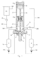
- Figure 1 shows a high-pressure self-cleaning mixing apparatus, of the linear type for mixing reactive chemical components into a resulting mixture, for example a polyol, an isocyanate and additives in the production of polyurethane foams and moulded articles.
- the mixing apparatus comprises a body 11 having a mixing chamber 12 axially aligned to an outlet duct 13 for delivering a mixture resulting from at least two reactive chemical components A and B contained in respective storage tanks 14 and 15.
- the mixing apparatus 10 comprises a cleaning device for the outlet duct 13 substantially provided by a reciprocable piston element 18 tightly sliding in the outlet duct 13.
- the piston element 18 is operatively connected to the piston 20 of a hydraulic actuator 21 by a piston rod 19 having a diameter smaller than the inner diameter of the mixing chamber 12 and the outlet duct 13, for the reasons explained further on.
- the mixing apparatus 10 is provided with a lubricant self-feeding and flushing device capable of preventing a reaction between the chemical components of the resulting mixture adhering to the outlet duct, and to reduce the frictional forces between the piston element 18 and inside surface of the outlet duct 13; therefore the sticking caused by the film of reacted mixture normally adhering to the cleaning member and the inner surface of the duct 13 is avoided, allowing at the same time the removal of the scraped particles of the reacted mixture, from the same outlet duct.
- the lubricant self-feeding device comprises a chamber 22 for containing and supplying an amount of lubricant, rearwardly positioned in respect to the body 11 of the mixing head; the lubricant chamber 22 is axially aligned and in direct fluid communication with the outlet duct 13, between the body 11 and the actuator 21.
- the lubricant chamber 22 is connected to a lubricant storage tank 23 by a recirculation circuit, forming a closed loop; more precisely the recirculation circuit comprises a first feeding duct 24A for sucking the lubricant from the storage tank 23 into the chamber 22, and a second duct 24B for recirculation of the lubricant from the chamber 22 to the storage tank 23, due to the pumping action of the piston element 18.
- Each of the ducts 24A and 24B is provided with a respective non-return valve 25A and 25B, while a filter 26 in the feeding duct 24A prevents any pollutants or scraped particles accumulated in the storage tank 23 from again being sucked into the lubricant chamber 22, thereby ensuring that filtered lubricant is constantly fed into the chamber 22, and into the outlet duct at each shot, as will be explained further on.
- the lubricant feeding device also comprises pumping means provided by the piston 18 of the cleaning device, operatively connected to the actuator 21, for feeding lubricant into an annular space 38 ( figures 4 and 5 ) provided between the outlet duct 13 and the piston rod 19 in the advanced condition of the piston 18, and causing circulation of the same lubricant between the annular space 38 and the lubricant chamber 22, respectively between the chamber 22 and the storage tank 23 by the reciprocating movement of the piston element 18.
- pumping means provided by the piston 18 of the cleaning device, operatively connected to the actuator 21, for feeding lubricant into an annular space 38 ( figures 4 and 5 ) provided between the outlet duct 13 and the piston rod 19 in the advanced condition of the piston 18, and causing circulation of the same lubricant between the annular space 38 and the lubricant chamber 22, respectively between the chamber 22 and the storage tank 23 by the reciprocating movement of the piston element 18.
- the cleaning member is in the form of a piston element 18 having a diameter larger than the piston rod 19, and conformed to simultaneously perform several working functions, in particular: a first ejecting action of the residual mixture which remains in the duct 13 at the end of each shot or delivering step of the chemical mixture; a second pumping action for sucking and flushing the lubricant in the annular space 38 between the opposite surfaces of the piston rod 19 and the outlet duct 13.
- the piston element 18 is also conformed for performing a third working action for scraping the film of reacted mixture that tends to adhere to the inner surface of the outlet duct 13.
- the scraping action of the piston element 18, can be performed in combination with the pumping and circulation of the lubricant flow.
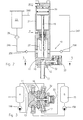
- figures 2 and 3 show a longitudinal cross-sectional view of a second type of mixing apparatus, for example of the type described in US-A-961.853 , provided with a self lubricating device according to the invention, as previously described for the example of fig. 1 ; therefore, in figures 2 and 3 the same reference numbers of figure 1 have been used for similar or equivalent parts.
- the embodiment of figures 2 and 3 differs from the solution of figure 1 due to the different disposition of the lubricant supply chamber 22, the mixing chamber 12 and the outlet duct 13.
- the lubricant supply chamber 22 is axially aligned and in fluid communication with the outlet duct 13, through the mixing chamber 12; conversely in the embodiment of figures 2 and 3 , the mixing chamber 12 and the outlet duct 13 are arranged with a "L" disposition in which the mixing chamber 12 is transversally arranged on a side of the outlet duct 13, and in which the lubricant supply chamber 22 is again axially aligned and in direct communication with the outlet duct 13.
- a second cleaning member 32 is reciprocable in the mixing chamber 12 by a second hydraulic actuator 33 which is sequentially controlled in respect to actuator 21 for the pumping piston 18 and cleaning member of the outlet duct 13.
- the apparatus of figures 2 and 3 works in an identical way to the apparatus of figure 1 .
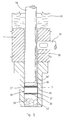
- Figure 4 shows a first embodiment of a cleaning member, in the form of a piston 18 capable of performing besides the cleaning of the outlet duct 13, both the pumping of the lubricant, and a scraping action for removing the reacted mixture that has adhered to the inner surface of the outlet duct 13.
- the piston member 18 comprises a cylindrical body 34 extending between end cross surfaces 34', for a short length smaller than the axial length of the outlet duct 13; the piston member 18 is provided with annular sealing and scraping elements 35, elastically yielding and radially urged against the inner surface 13' of the outlet duct 13; sharp edges of the annular elements 35 exert an efficient scraping action against the internal surface 13' of the outlet duct 13, during reciprocating movement of the same piston member 18.
- Each of the scraping elements 35 in the example of figure 4 is in the form of a split metal ring having an "L" or "Z" shaped-cross cut; one or more metal rings 35 may be seated in corresponding annular grooves 36 of the piston body 34; in place of, or in combination with the rings 35 of figure 4 , it is possible to use the spirally shaped rings 37 of figure 5 , providing in any case an external diameter of the rings 35 and 37 of a few tenths or hundredths of millimetre greater than the internal diameter of the outlet duct 13 up to a 10 percent; therefore the sealing and scraping rings 35 and 37 may be elastically urged into contact with the internal surface 13' of said outlet duct 13.
- Figures 4 and 5 illustrate the use of a cleaning member 18 in the form of a pumping and scraping piston of limited length, only slightly longer than the inner diameter of the outlet duct 13; however, the length of the cleaning and pumping piston 18, and the number of sealing and scraping rings 35 and 37 can also differ from what has been shown; for example, the length of the body 34 of the cleaning piston member 18 can range from 0.5 to 5 times the internal diameter of the outlet duct 13, and the scraping members can be of any number, for example ranging from 1 to 10.
- the cleaning member 18 is in the totally backward or retracted position of figure 2 , to close the fluid communication between the lubricant supply chamber 22 and the mixing chamber 12 in figure 1 , or the outlet duct 13 in figure 2 ; simultaneously, the cleaning member 32 for the mixing chamber 12 of the embodiment of figures 2 and 3 is also in the backward position in which it opens the injectors 16 and 17 towards the mixing chamber 12.
- the chemical components A and B fed by respective metering pumps 14A and 15A, are injected into and thoroughly mixed into the chamber 12, from which the resulting mixture is discharged through the outlet duct 13.
- the cleaning member 18 remains in the fully backward position with the piston rod 29 of the control piston 20 partially immersed in the lubricant contained in the supply chamber 22.
- the cleaning member 18 in addition to ejecting the residual mixture, scrapes the film of mixture that remains adhering to the internal surface 13' of the outlet duct 13.
- the cleaning member 18 performs a pumping action for flushing the lubricant.
- an annular space 38 is provided between the opposite surfaces of the piston rod 19 and of the outlet duct 13; in this way the lubricant is sucked from the supply chamber 22 into the annular space 38, totally wetting the inner surface of the delivery duct 13, which at the same time the cleaning member 18 has scraped, ejecting the reactive chemical mixture.
- the cleaning member 18 Before starting of a subsequent mixing step, the cleaning member 18 is again moved back to the retracted position of figure 2 ; during its backward movement, the cleaning piston member 18 again performs a pumping and scraping action, in the opposite direction to the previous one, flushing the lubricant and scraped particles of the reacted mixture from the annular space 38 of the outlet duct 13 into the supply chamber 22, simultaneously causing the re-circulation of the lubricant from the chamber 22 to the storage tank 23, along the duct 24B; in this way, it is possible to carry out an efficient flushing action and a periodical change of lubricant in the supply chamber 22 of the mixing apparatus, preventing the scraped particles of reacted material to accumulate in the lubricant and depositing into the chamber 22.
- Figures 1 , 2 , 4 and 5 show several examples of cleaning and lubricant pumping devices, according to the invention, applied to two different types of high-pressure mixing apparatuses; it is obvious however that what has been described and shown with reference to the aforesaid figures, has been given purely by way of example in order to illustrate the present invention and some possible solutions.
Landscapes
- Engineering & Computer Science (AREA)
- Mechanical Engineering (AREA)
- Processing And Handling Of Plastics And Other Materials For Molding In General (AREA)
- Accessories For Mixers (AREA)
- Lubricants (AREA)
Applications Claiming Priority (2)
| Application Number | Priority Date | Filing Date | Title |
|---|---|---|---|
| IT002315A ITMI20062315A1 (it) | 2006-11-30 | 2006-11-30 | Metodo e apparecchiatura di miscelazione ad alta pressione con dispositivo di autolubrificazione raschiatura e flussaggio |
| EP07021087A EP1927448B9 (fr) | 2006-11-30 | 2007-10-29 | Procédé et appareil de mélange haute pression doté d'un dispositif de raclage autolubrifiant |
Related Parent Applications (2)
| Application Number | Title | Priority Date | Filing Date |
|---|---|---|---|
| EP07021087.7 Division | 2007-10-29 | ||
| EP07021087 Previously-Filed-Application | 2007-10-29 |
Publications (3)
| Publication Number | Publication Date |
|---|---|
| EP2233268A2 true EP2233268A2 (fr) | 2010-09-29 |
| EP2233268A3 EP2233268A3 (fr) | 2010-11-24 |
| EP2233268B1 EP2233268B1 (fr) | 2013-01-30 |
Family
ID=39145379
Family Applications (2)
| Application Number | Title | Priority Date | Filing Date |
|---|---|---|---|
| EP07021087A Not-in-force EP1927448B9 (fr) | 2006-11-30 | 2007-10-29 | Procédé et appareil de mélange haute pression doté d'un dispositif de raclage autolubrifiant |
| EP10165886A Not-in-force EP2233268B1 (fr) | 2006-11-30 | 2007-10-29 | Appareil de mélange haute pression doté d'un dispositif de raclage |
Family Applications Before (1)
| Application Number | Title | Priority Date | Filing Date |
|---|---|---|---|
| EP07021087A Not-in-force EP1927448B9 (fr) | 2006-11-30 | 2007-10-29 | Procédé et appareil de mélange haute pression doté d'un dispositif de raclage autolubrifiant |
Country Status (4)
| Country | Link |
|---|---|
| US (1) | US7553066B2 (fr) |
| EP (2) | EP1927448B9 (fr) |
| AT (1) | ATE523306T1 (fr) |
| IT (1) | ITMI20062315A1 (fr) |
Cited By (1)
| Publication number | Priority date | Publication date | Assignee | Title |
|---|---|---|---|---|
| WO2021069080A1 (fr) * | 2019-10-11 | 2021-04-15 | Kraussmaffei Technologies Gmbh | Dispositif de mélange lubrifié pour matières plastiques de réaction |
Families Citing this family (12)
| Publication number | Priority date | Publication date | Assignee | Title |
|---|---|---|---|---|
| ITMI20062315A1 (it) * | 2006-11-30 | 2008-06-01 | Afros Spa | Metodo e apparecchiatura di miscelazione ad alta pressione con dispositivo di autolubrificazione raschiatura e flussaggio |
| BR112012006248A2 (pt) * | 2009-11-04 | 2019-09-24 | Graco Minnesota Inc | "cartucho de lubrificação com haste de abertura de válvula integrada." |
| ITMI20130216A1 (it) * | 2013-02-15 | 2014-08-16 | Afros Spa | Metodo e apparecchiatura di miscelazione ad alta pressione con tenuta autorigenerante |
| CN103437983A (zh) * | 2013-08-12 | 2013-12-11 | 米顿罗工业设备(上海)有限公司 | 一种适用于输送浆料的隔膜泵结构 |
| DE102015112445A1 (de) | 2015-07-30 | 2017-02-02 | Kraussmaffei Technologies Gmbh | Mischkopf mit einer Schmiereinrichtung für einen Reinigungskolben |
| BR112018008994A8 (pt) | 2015-11-12 | 2019-02-26 | Akzo Nobel Coatings Int Bv | máquina pigmentadora, e método de liberação de um ou mais corantes em um recipiente de tinta com tinta base |
| DE102015119813A1 (de) * | 2015-11-17 | 2017-05-18 | Kraussmaffei Technologies Gmbh | Reinigungskolben mit unpolarem Werkstoff sowie Mischkopf mit Reinigungskolben und Auslaufkanal |
| KR101887209B1 (ko) * | 2017-02-08 | 2018-08-09 | (주)디유티코리아 | 섬유강화 복합재료 수지 주입용 믹싱헤드 |
| BE1025001B1 (nl) | 2017-09-19 | 2018-09-14 | Free Wheeler Ltd. | Mengmachine |
| IT201800010844A1 (it) | 2018-12-05 | 2020-06-05 | Afros Spa | Elemento a guarnizione di tenuta per un’apparecchiatura di miscelazione, metodo di ottenimento ed applicazione dello stesso e relativa attrezzatura speciale di montaggio. |
| IT201900004603A1 (it) * | 2019-03-27 | 2020-09-27 | Afros Spa | Dispositivo di miscelazione ad alta pressione con condotto di erogazione in singolo pezzo |
| IT202400003406A1 (it) | 2024-02-19 | 2025-08-19 | Astom S R L | Testa di iniezione di schiume polimeriche espansibili con controllo antigrippaggio |
Citations (4)
| Publication number | Priority date | Publication date | Assignee | Title |
|---|---|---|---|---|
| US3687370A (en) | 1971-01-18 | 1972-08-29 | Instapak Corp | Liquid mixing and dispensing apparatus |
| US4469251A (en) | 1981-09-02 | 1984-09-04 | Sealed Air Corporation | Detachable mixing chamber for a fluid dispensing apparatus |
| DE8915329U1 (de) | 1989-03-10 | 1990-04-12 | Krauss-Maffei AG, 8000 München | Vorrichtung zum Mischen von wenigstens zwei reaktiven Kunststoffkomponenten |
| US5785422A (en) | 1995-04-24 | 1998-07-28 | Krauss-Maffei Ag | Piston arrangement for removing a reactive plastic mixture from a stabilizing chamber of a mixing device |
Family Cites Families (16)
| Publication number | Priority date | Publication date | Assignee | Title |
|---|---|---|---|---|
| US1511576A (en) * | 1922-04-18 | 1924-10-14 | Parkin Henry | Piston ring |
| US1819890A (en) * | 1930-07-26 | 1931-08-18 | Charles J Gleason | Piston ring |
| US1833887A (en) * | 1930-12-03 | 1931-12-01 | William C Andrews | Piston ring |
| US3786990A (en) * | 1972-07-17 | 1974-01-22 | Graco Inc | Plural component gun |
| US3912234A (en) * | 1974-08-29 | 1975-10-14 | Cincinnati Milacron Inc | Apparatus for mixing and injecting liquids into a mold |
| US3945569A (en) * | 1974-10-25 | 1976-03-23 | Instapak Corporation | Foam dispensing apparatus |
| DE2555156C3 (de) | 1975-12-08 | 1987-07-09 | The Dow Chemical Co. (eine Ges.n.d.Gesetzen d. Staates Delaware), Midland, Mich. | Hochdruck-Mischkopf |
| IT1109997B (it) | 1978-03-09 | 1985-12-23 | Afros Srl | Testa per la miscelazione e l'eiezione di componenti liquidi interagenti per lo stampaggio di materiali plastici |
| JPS5532645A (en) * | 1978-08-31 | 1980-03-07 | Inoue Mtp Co Ltd | Mixing device for multicomponent synthetic resin, particularly polyurethane particularly |
| DE2838798B2 (de) * | 1978-09-06 | 1980-07-10 | Elastogran Maschinenbau Gmbh & Co, 8021 Strasslach | Mischvorrichtung für miteinander chemisch reagierende, flüssige Komponenten, vorzugsweise Polyurethan bildende |
| DE2928915A1 (de) * | 1979-07-18 | 1981-02-12 | Bayer Ag | Injektionsmischkopf |
| US5027975A (en) * | 1989-12-14 | 1991-07-02 | Keske David G | Urethane foam gun |
| US5339724A (en) * | 1991-03-05 | 1994-08-23 | Wartsila Diesel International Ltd. Oy | Arrangement for the lubrication of the piston member of a fuel injection pump |
| DE4214404A1 (de) * | 1992-04-30 | 1993-11-04 | Krauss Maffei Ag | Vorrichtung zum mischen von mindestens zwei reaktiven kunststoffkomponenten |
| US7093972B2 (en) * | 2003-06-20 | 2006-08-22 | Mhr, Inc. | Tri-tilt mixing head |
| ITMI20062315A1 (it) * | 2006-11-30 | 2008-06-01 | Afros Spa | Metodo e apparecchiatura di miscelazione ad alta pressione con dispositivo di autolubrificazione raschiatura e flussaggio |
-
2006
- 2006-11-30 IT IT002315A patent/ITMI20062315A1/it unknown
-
2007
- 2007-10-29 EP EP07021087A patent/EP1927448B9/fr not_active Not-in-force
- 2007-10-29 AT AT07021087T patent/ATE523306T1/de not_active IP Right Cessation
- 2007-10-29 EP EP10165886A patent/EP2233268B1/fr not_active Not-in-force
- 2007-11-29 US US11/946,955 patent/US7553066B2/en not_active Expired - Fee Related
Patent Citations (4)
| Publication number | Priority date | Publication date | Assignee | Title |
|---|---|---|---|---|
| US3687370A (en) | 1971-01-18 | 1972-08-29 | Instapak Corp | Liquid mixing and dispensing apparatus |
| US4469251A (en) | 1981-09-02 | 1984-09-04 | Sealed Air Corporation | Detachable mixing chamber for a fluid dispensing apparatus |
| DE8915329U1 (de) | 1989-03-10 | 1990-04-12 | Krauss-Maffei AG, 8000 München | Vorrichtung zum Mischen von wenigstens zwei reaktiven Kunststoffkomponenten |
| US5785422A (en) | 1995-04-24 | 1998-07-28 | Krauss-Maffei Ag | Piston arrangement for removing a reactive plastic mixture from a stabilizing chamber of a mixing device |
Cited By (3)
| Publication number | Priority date | Publication date | Assignee | Title |
|---|---|---|---|---|
| WO2021069080A1 (fr) * | 2019-10-11 | 2021-04-15 | Kraussmaffei Technologies Gmbh | Dispositif de mélange lubrifié pour matières plastiques de réaction |
| WO2021069483A1 (fr) * | 2019-10-11 | 2021-04-15 | Kraussmaffei Technologies Gmbh | Dispositif lubrifié de mélange pour matières plastiques de réaction et procédé de génération de matières plastiques de réaction |
| US12390778B2 (en) | 2019-10-11 | 2025-08-19 | Kraussmaffei Technologies Gmbh | Lubricated mixing device for reaction plastics and method for generating reaction plastics |
Also Published As
| Publication number | Publication date |
|---|---|
| EP1927448A3 (fr) | 2009-04-22 |
| US20080128209A1 (en) | 2008-06-05 |
| EP2233268B1 (fr) | 2013-01-30 |
| EP2233268A3 (fr) | 2010-11-24 |
| ITMI20062315A1 (it) | 2008-06-01 |
| EP1927448A2 (fr) | 2008-06-04 |
| EP1927448B9 (fr) | 2012-03-21 |
| EP1927448B1 (fr) | 2011-09-07 |
| ATE523306T1 (de) | 2011-09-15 |
| US7553066B2 (en) | 2009-06-30 |
Similar Documents
| Publication | Publication Date | Title |
|---|---|---|
| EP1927448B1 (fr) | Procédé et appareil de mélange haute pression doté d'un dispositif de raclage autolubrifiant | |
| US5163584A (en) | Method and apparatus for mixing and dispensing foam with injected low pressure gas | |
| EP2767376B2 (fr) | Procédé et appareil de mélange à haute pression avec joint auto-régénérant | |
| KR100426755B1 (ko) | 용제세척식반응사출성형혼합헤드 | |
| WO1999006196A1 (fr) | Systeme de distribution, composants de ce systeme et procede de fabrication, de fonctionnement et de mise en service d'un systeme de distribution et de ses composants | |
| CN110882870A (zh) | 多液混合涂料的供给系统及多液混合涂料的供给方法 | |
| JP3703625B2 (ja) | ポリウレタン混合物を製造する自己洗浄混合装置およびその方法 | |
| KR102028035B1 (ko) | 크리닝로드 제어기능을 갖는 발포폼 믹싱헤드장치 | |
| JP7488038B2 (ja) | 流体をスプレイするための装置及び関連方法 | |
| US9441617B2 (en) | Liquid delivery method and apparatus | |
| US7455446B2 (en) | Co-injection mixing method and apparatus | |
| EP0113222A2 (fr) | Buse d'injection à contre-courant | |
| US4452919A (en) | High velocity mixing method | |
| US4463881A (en) | Injector for molding hardenable liquid precursors | |
| CN113432027B (zh) | 一种油脂泵头和油脂泵 | |
| KR100478342B1 (ko) | 공작기계의 절삭액 공급장치 | |
| CN112776246B (zh) | 注射装置以及注射装置的气体溶解方法 | |
| KR100325577B1 (ko) | 그리스 토출장치 | |
| JP2003190847A (ja) | 塗料送給装置 | |
| JPH07259728A (ja) | 粘性流体圧送装置の残留粘性流体排出装置 | |
| JP4412686B2 (ja) | ウレタンエラストマーの製法および衝突混合装置 | |
| KR20040103229A (ko) | 자동여과장치 | |
| JP2023155807A (ja) | 液体供給装置および液体吐出装置 | |
| JP2009029565A (ja) | 潤滑剤供給装置 | |
| JPH09291793A (ja) | シールド工法における注入口部材の洗浄方法及び洗浄装置 |
Legal Events
| Date | Code | Title | Description |
|---|---|---|---|
| PUAI | Public reference made under article 153(3) epc to a published international application that has entered the european phase |
Free format text: ORIGINAL CODE: 0009012 |
|
| AC | Divisional application: reference to earlier application |
Ref document number: 1927448 Country of ref document: EP Kind code of ref document: P |
|
| AK | Designated contracting states |
Kind code of ref document: A2 Designated state(s): AT BE BG CH CY CZ DE DK EE ES FI FR GB GR HU IE IS IT LI LT LU LV MC MT NL PL PT RO SE SI SK TR |
|
| AX | Request for extension of the european patent |
Extension state: AL BA HR MK RS |
|
| PUAL | Search report despatched |
Free format text: ORIGINAL CODE: 0009013 |
|
| AK | Designated contracting states |
Kind code of ref document: A3 Designated state(s): AT BE BG CH CY CZ DE DK EE ES FI FR GB GR HU IE IS IT LI LT LU LV MC MT NL PL PT RO SE SI SK TR |
|
| AX | Request for extension of the european patent |
Extension state: AL BA HR MK RS |
|
| 17P | Request for examination filed |
Effective date: 20110520 |
|
| 17Q | First examination report despatched |
Effective date: 20111007 |
|
| GRAP | Despatch of communication of intention to grant a patent |
Free format text: ORIGINAL CODE: EPIDOSNIGR1 |
|
| GRAS | Grant fee paid |
Free format text: ORIGINAL CODE: EPIDOSNIGR3 |
|
| GRAA | (expected) grant |
Free format text: ORIGINAL CODE: 0009210 |
|
| AC | Divisional application: reference to earlier application |
Ref document number: 1927448 Country of ref document: EP Kind code of ref document: P |
|
| AK | Designated contracting states |
Kind code of ref document: B1 Designated state(s): AT BE BG CH CY CZ DE DK EE ES FI FR GB GR HU IE IS IT LI LT LU LV MC MT NL PL PT RO SE SI SK TR |
|
| REG | Reference to a national code |
Ref country code: GB Ref legal event code: FG4D |
|
| REG | Reference to a national code |
Ref country code: CH Ref legal event code: EP |
|
| REG | Reference to a national code |
Ref country code: AT Ref legal event code: REF Ref document number: 595631 Country of ref document: AT Kind code of ref document: T Effective date: 20130215 Ref country code: CH Ref legal event code: EP |
|
| REG | Reference to a national code |
Ref country code: IE Ref legal event code: FG4D |
|
| REG | Reference to a national code |
Ref country code: CH Ref legal event code: PCOW Free format text: NEW ADDRESS: C/O COLOBERTI & LUPPI SRL VIA E. DE AMICIS 25, 20123 MILANO (IT) |
|
| REG | Reference to a national code |
Ref country code: DE Ref legal event code: R096 Ref document number: 602007028344 Country of ref document: DE Effective date: 20130328 |
|
| REG | Reference to a national code |
Ref country code: AT Ref legal event code: MK05 Ref document number: 595631 Country of ref document: AT Kind code of ref document: T Effective date: 20130130 |
|
| REG | Reference to a national code |
Ref country code: LT Ref legal event code: MG4D |
|
| REG | Reference to a national code |
Ref country code: NL Ref legal event code: VDEP Effective date: 20130130 |
|
| PG25 | Lapsed in a contracting state [announced via postgrant information from national office to epo] |
Ref country code: BE Free format text: LAPSE BECAUSE OF FAILURE TO SUBMIT A TRANSLATION OF THE DESCRIPTION OR TO PAY THE FEE WITHIN THE PRESCRIBED TIME-LIMIT Effective date: 20130130 Ref country code: LT Free format text: LAPSE BECAUSE OF FAILURE TO SUBMIT A TRANSLATION OF THE DESCRIPTION OR TO PAY THE FEE WITHIN THE PRESCRIBED TIME-LIMIT Effective date: 20130130 Ref country code: ES Free format text: LAPSE BECAUSE OF FAILURE TO SUBMIT A TRANSLATION OF THE DESCRIPTION OR TO PAY THE FEE WITHIN THE PRESCRIBED TIME-LIMIT Effective date: 20130511 Ref country code: AT Free format text: LAPSE BECAUSE OF FAILURE TO SUBMIT A TRANSLATION OF THE DESCRIPTION OR TO PAY THE FEE WITHIN THE PRESCRIBED TIME-LIMIT Effective date: 20130130 Ref country code: IS Free format text: LAPSE BECAUSE OF FAILURE TO SUBMIT A TRANSLATION OF THE DESCRIPTION OR TO PAY THE FEE WITHIN THE PRESCRIBED TIME-LIMIT Effective date: 20130530 Ref country code: BG Free format text: LAPSE BECAUSE OF FAILURE TO SUBMIT A TRANSLATION OF THE DESCRIPTION OR TO PAY THE FEE WITHIN THE PRESCRIBED TIME-LIMIT Effective date: 20130430 Ref country code: SE Free format text: LAPSE BECAUSE OF FAILURE TO SUBMIT A TRANSLATION OF THE DESCRIPTION OR TO PAY THE FEE WITHIN THE PRESCRIBED TIME-LIMIT Effective date: 20130130 |
|
| PG25 | Lapsed in a contracting state [announced via postgrant information from national office to epo] |
Ref country code: FI Free format text: LAPSE BECAUSE OF FAILURE TO SUBMIT A TRANSLATION OF THE DESCRIPTION OR TO PAY THE FEE WITHIN THE PRESCRIBED TIME-LIMIT Effective date: 20130130 Ref country code: PL Free format text: LAPSE BECAUSE OF FAILURE TO SUBMIT A TRANSLATION OF THE DESCRIPTION OR TO PAY THE FEE WITHIN THE PRESCRIBED TIME-LIMIT Effective date: 20130130 Ref country code: LV Free format text: LAPSE BECAUSE OF FAILURE TO SUBMIT A TRANSLATION OF THE DESCRIPTION OR TO PAY THE FEE WITHIN THE PRESCRIBED TIME-LIMIT Effective date: 20130130 Ref country code: PT Free format text: LAPSE BECAUSE OF FAILURE TO SUBMIT A TRANSLATION OF THE DESCRIPTION OR TO PAY THE FEE WITHIN THE PRESCRIBED TIME-LIMIT Effective date: 20130530 Ref country code: GR Free format text: LAPSE BECAUSE OF FAILURE TO SUBMIT A TRANSLATION OF THE DESCRIPTION OR TO PAY THE FEE WITHIN THE PRESCRIBED TIME-LIMIT Effective date: 20130501 Ref country code: NL Free format text: LAPSE BECAUSE OF FAILURE TO SUBMIT A TRANSLATION OF THE DESCRIPTION OR TO PAY THE FEE WITHIN THE PRESCRIBED TIME-LIMIT Effective date: 20130130 Ref country code: SI Free format text: LAPSE BECAUSE OF FAILURE TO SUBMIT A TRANSLATION OF THE DESCRIPTION OR TO PAY THE FEE WITHIN THE PRESCRIBED TIME-LIMIT Effective date: 20130130 |
|
| PG25 | Lapsed in a contracting state [announced via postgrant information from national office to epo] |
Ref country code: RO Free format text: LAPSE BECAUSE OF FAILURE TO SUBMIT A TRANSLATION OF THE DESCRIPTION OR TO PAY THE FEE WITHIN THE PRESCRIBED TIME-LIMIT Effective date: 20130130 Ref country code: SK Free format text: LAPSE BECAUSE OF FAILURE TO SUBMIT A TRANSLATION OF THE DESCRIPTION OR TO PAY THE FEE WITHIN THE PRESCRIBED TIME-LIMIT Effective date: 20130130 Ref country code: CZ Free format text: LAPSE BECAUSE OF FAILURE TO SUBMIT A TRANSLATION OF THE DESCRIPTION OR TO PAY THE FEE WITHIN THE PRESCRIBED TIME-LIMIT Effective date: 20130130 Ref country code: DK Free format text: LAPSE BECAUSE OF FAILURE TO SUBMIT A TRANSLATION OF THE DESCRIPTION OR TO PAY THE FEE WITHIN THE PRESCRIBED TIME-LIMIT Effective date: 20130130 Ref country code: EE Free format text: LAPSE BECAUSE OF FAILURE TO SUBMIT A TRANSLATION OF THE DESCRIPTION OR TO PAY THE FEE WITHIN THE PRESCRIBED TIME-LIMIT Effective date: 20130130 |
|
| PG25 | Lapsed in a contracting state [announced via postgrant information from national office to epo] |
Ref country code: CY Free format text: LAPSE BECAUSE OF FAILURE TO SUBMIT A TRANSLATION OF THE DESCRIPTION OR TO PAY THE FEE WITHIN THE PRESCRIBED TIME-LIMIT Effective date: 20130130 |
|
| PLBE | No opposition filed within time limit |
Free format text: ORIGINAL CODE: 0009261 |
|
| STAA | Information on the status of an ep patent application or granted ep patent |
Free format text: STATUS: NO OPPOSITION FILED WITHIN TIME LIMIT |
|
| 26N | No opposition filed |
Effective date: 20131031 |
|
| REG | Reference to a national code |
Ref country code: DE Ref legal event code: R097 Ref document number: 602007028344 Country of ref document: DE Effective date: 20131031 |
|
| PG25 | Lapsed in a contracting state [announced via postgrant information from national office to epo] |
Ref country code: MC Free format text: LAPSE BECAUSE OF FAILURE TO SUBMIT A TRANSLATION OF THE DESCRIPTION OR TO PAY THE FEE WITHIN THE PRESCRIBED TIME-LIMIT Effective date: 20130130 |
|
| REG | Reference to a national code |
Ref country code: CH Ref legal event code: PL |
|
| GBPC | Gb: european patent ceased through non-payment of renewal fee |
Effective date: 20131029 |
|
| REG | Reference to a national code |
Ref country code: IE Ref legal event code: MM4A |
|
| PG25 | Lapsed in a contracting state [announced via postgrant information from national office to epo] |
Ref country code: GB Free format text: LAPSE BECAUSE OF NON-PAYMENT OF DUE FEES Effective date: 20131029 Ref country code: LI Free format text: LAPSE BECAUSE OF NON-PAYMENT OF DUE FEES Effective date: 20131031 Ref country code: CH Free format text: LAPSE BECAUSE OF NON-PAYMENT OF DUE FEES Effective date: 20131031 |
|
| REG | Reference to a national code |
Ref country code: FR Ref legal event code: ST Effective date: 20140630 |
|
| PG25 | Lapsed in a contracting state [announced via postgrant information from national office to epo] |
Ref country code: FR Free format text: LAPSE BECAUSE OF NON-PAYMENT OF DUE FEES Effective date: 20131031 |
|
| PG25 | Lapsed in a contracting state [announced via postgrant information from national office to epo] |
Ref country code: IE Free format text: LAPSE BECAUSE OF NON-PAYMENT OF DUE FEES Effective date: 20131029 |
|
| PG25 | Lapsed in a contracting state [announced via postgrant information from national office to epo] |
Ref country code: TR Free format text: LAPSE BECAUSE OF FAILURE TO SUBMIT A TRANSLATION OF THE DESCRIPTION OR TO PAY THE FEE WITHIN THE PRESCRIBED TIME-LIMIT Effective date: 20130130 |
|
| PG25 | Lapsed in a contracting state [announced via postgrant information from national office to epo] |
Ref country code: HU Free format text: LAPSE BECAUSE OF FAILURE TO SUBMIT A TRANSLATION OF THE DESCRIPTION OR TO PAY THE FEE WITHIN THE PRESCRIBED TIME-LIMIT; INVALID AB INITIO Effective date: 20071029 Ref country code: LU Free format text: LAPSE BECAUSE OF NON-PAYMENT OF DUE FEES Effective date: 20131029 |
|
| PG25 | Lapsed in a contracting state [announced via postgrant information from national office to epo] |
Ref country code: MT Free format text: LAPSE BECAUSE OF FAILURE TO SUBMIT A TRANSLATION OF THE DESCRIPTION OR TO PAY THE FEE WITHIN THE PRESCRIBED TIME-LIMIT Effective date: 20130130 |
|
| PGFP | Annual fee paid to national office [announced via postgrant information from national office to epo] |
Ref country code: IT Payment date: 20151029 Year of fee payment: 9 Ref country code: DE Payment date: 20151022 Year of fee payment: 9 |
|
| REG | Reference to a national code |
Ref country code: DE Ref legal event code: R119 Ref document number: 602007028344 Country of ref document: DE |
|
| PG25 | Lapsed in a contracting state [announced via postgrant information from national office to epo] |
Ref country code: DE Free format text: LAPSE BECAUSE OF NON-PAYMENT OF DUE FEES Effective date: 20170503 |
|
| PG25 | Lapsed in a contracting state [announced via postgrant information from national office to epo] |
Ref country code: IT Free format text: LAPSE BECAUSE OF NON-PAYMENT OF DUE FEES Effective date: 20161029 |