EP2233357A2 - Dispositif de support de commande, procédé de support de commande, et programme de support de commande - Google Patents
Dispositif de support de commande, procédé de support de commande, et programme de support de commande Download PDFInfo
- Publication number
- EP2233357A2 EP2233357A2 EP10001227A EP10001227A EP2233357A2 EP 2233357 A2 EP2233357 A2 EP 2233357A2 EP 10001227 A EP10001227 A EP 10001227A EP 10001227 A EP10001227 A EP 10001227A EP 2233357 A2 EP2233357 A2 EP 2233357A2
- Authority
- EP
- European Patent Office
- Prior art keywords
- movement
- vehicle
- overhead
- image
- parameter
- Prior art date
- Legal status (The legal status is an assumption and is not a legal conclusion. Google has not performed a legal analysis and makes no representation as to the accuracy of the status listed.)
- Granted
Links
Images





Classifications
-
- G—PHYSICS
- G06—COMPUTING OR CALCULATING; COUNTING
- G06T—IMAGE DATA PROCESSING OR GENERATION, IN GENERAL
- G06T7/00—Image analysis
- G06T7/80—Analysis of captured images to determine intrinsic or extrinsic camera parameters, i.e. camera calibration
-
- G—PHYSICS
- G06—COMPUTING OR CALCULATING; COUNTING
- G06V—IMAGE OR VIDEO RECOGNITION OR UNDERSTANDING
- G06V20/00—Scenes; Scene-specific elements
- G06V20/50—Context or environment of the image
- G06V20/56—Context or environment of the image exterior to a vehicle by using sensors mounted on the vehicle
- G06V20/588—Recognition of the road, e.g. of lane markings; Recognition of the vehicle driving pattern in relation to the road
-
- B—PERFORMING OPERATIONS; TRANSPORTING
- B60—VEHICLES IN GENERAL
- B60R—VEHICLES, VEHICLE FITTINGS, OR VEHICLE PARTS, NOT OTHERWISE PROVIDED FOR
- B60R2300/00—Details of viewing arrangements using cameras and displays, specially adapted for use in a vehicle
- B60R2300/60—Details of viewing arrangements using cameras and displays, specially adapted for use in a vehicle characterised by monitoring and displaying vehicle exterior scenes from a transformed perspective
-
- G—PHYSICS
- G06—COMPUTING OR CALCULATING; COUNTING
- G06T—IMAGE DATA PROCESSING OR GENERATION, IN GENERAL
- G06T2207/00—Indexing scheme for image analysis or image enhancement
- G06T2207/20—Special algorithmic details
- G06T2207/20092—Interactive image processing based on input by user
Definitions
- the present invention relates to a driving support device, a driving support method, and a driving support program.
- a driving support device that displays an image of a vicinity of a vehicle on a display.
- the driving support device displays image data of the vicinity of the vehicle, which is imaged by a camera that is installed at an external side of the vehicle, on the display allocated in the vicinity of a driver seat.
- a driving support system in which the position and the angle of the image displayed on the display can be arranged.
- a driving support system which, in order to realize adjustment of a bird's eye image with a relatively-simple operation, displays the overhead image converted from the bird's eye image together with a guide which indicates extended lines from the right and left ends of the vehicle on a display device and makes the user to correct the deviation between the image after the overhead conversion and the guide (refer to JP-A-2008-205928 (paragraph 0160) for example).
- a device which accumulates image data acquired from the camera in a memory and outputs a composite image created by compositing image data accumulated in the memory.
- This device in creating the composite image by compositing the image data, refers to parameters corresponding to, for example, the installed position of the camera, movement characteristic of the vehicle, and the like. Therefore, if the installed position of the camera, the movement characteristic of the vehicle, or the like changes, distortion and/or deviation can occur because the parameters do not correspond to the condition after the change.
- the above-mentioned conventional driving support system only the deviation in the image and the guide in the overhead image can be corrected, and the parameters used in creating the composite image cannot be corrected to appropriate values.
- the turn parameter which the movement status determining unit uses in determining a turn as the movement status based on the movement information, is calibrated.
- the turn parameter can be calibrated based on a difference between the position of the reference marker in the composite image and the predicted position thereof, and a precise composite image can be displayed by compositing the image data recorded in the recording unit using the calibrated turn parameter.
- the distance parameter which the movement status determining unit uses in determining a movement distance as the movement status based on the movement information, is calibrated.
- the distance parameter can be calibrated based on the difference between the position of the reference marker in the composite image and the predicted position thereof, and a precise composite image can be displayed by compositing the image data recorded in the recording unit using the calibrated distance parameter.
- the overhead parameter which the overhead image creating unit uses in creating the overhead image, is calibrated. Consequently, even if a precise overhead image cannot be displayed based on the overhead parameter due to a deviation of the installed position of the imaging unit, the overhead parameter can be calibrated based on the difference between the position of the reference marker in the composite image and the predicted position thereof, and a precise overhead image can be created using the calibrated overhead parameter.
- a position marker corresponding to the position of the vehicle is displayed in a part created based on the actual image data imaged by the imaging unit within the composite image that the composite image creating unit creates. Therefore, a target position when moving the vehicle by a predetermined distance can be presented based on such position marker, regardless of whether or not the part created based on the recorded image data within the composite image is precise.
- the distance parameter is calibrated after the overhead parameter was calibrated; therefore, the distance parameter can be calibrated based on the predicted position of the reference marker displayed in the precise overhead image.
- the turn parameter is calibrated after the distance parameter has been calibrated; therefore, the turn parameter can be calibrated based on the composite image and the predicted position of the reference marker created using the correct distance parameter.
- FIG. 1 is a block diagram illustrating a driving support device according to the embodiment.
- a driving support device 1 includes a steering sensor 10, a speed sensor 20, an operation input part 30, a camera 40, a display 50, a control part 60, and a data recording part 70.
- the steering sensor 10 detects a steering angle of a steering wheel of a vehicle and outputs the detected value to the control part 60.
- a generally-known steering sensor can be utilized.
- the speed sensor 20 outputs a speed pulse signal proportional to the number of rotations of an axle and the like to the control part 60.
- a generally-known speed sensor can be utilized.
- the operation input part 30 receives an operation input by an operator.
- a generally-known input unit such as a switch or a touch panel can be utilized.
- the camera 40 is an imaging unit that images a vicinity of the vehicle.
- the camera 40 one or a plurality of units is installed for example in the vicinity of front and/or rear bumpers of the vehicle, and images the vicinity of the vehicle.
- Image data imaged by the camera 40 is inputted to the control part 60.
- the camera 40 can have any specific configuration.
- a generally-known imaging device such as a CMOS image sensor, a CCD image sensor, and a generally-known optical part such as a fish-eye lens or a prism are utilized.
- the display 50 is a displaying unit that displays a composite image and an overhead image created by the control part 60.
- the display 50 can have any specific configuration.
- a flat panel display such as a generally-known liquid crystal display or an organic EL display can be utilized.
- the control part 60 is a controlling unit that controls the driving support device 1.
- the control part 60 is a computer that includes a CPU, various programs that are interpreted and executed in the CPU (including OS and other basic control programs, and application programs that are activated in the OS to carry out specific functions), and an internal memory such as a RAM for storing the programs and various data.
- a driving support program according to the present embodiment is installed in the driving support device 1 through any storage medium or network, and configures various parts of the control part 60 in substance.
- the control part 60 includes a movement status determining part 61, a composite image creating part 62, an overhead image creating part 63, a calibrating part 64, and an image memory 65 in terms of functional concept.
- the movement status determining part 61 is a movement status determining unit that acquires movement information relating to movement of the vehicle and determines movement status of the vehicle based on the acquired movement information.
- the "movement information” here includes the detected value of the steering angle inputted from the steering sensor 10 and the speed pulse signal inputted from the speed sensor 20.
- the "movement status” represents status relating to the movement of the vehicle such as a turn angle and a movement distance of the vehicle, for example.
- the composite image creating part 62 is a composite image creating unit that, based on the movement status determined by the movement status determining part 61, composites image data recorded in the data recording part 70 and creates a composite image of a range including a position of the vehicle.
- the overhead image creating part 63 is an overhead image creating unit that creates an overhead image of the range including the position of the vehicle based on the image data of the vicinity of the vehicle imaged by the camera 40.
- the calibrating part 64 is a calibrating unit that calibrates a parameter used when the movement status determining part 61 determines the movement status based on the movement information and an overhead parameter used when the overhead image creating part 63 creates the overhead image.
- the image memory 65 is a recording unit that records the image data of the vicinity of the vehicle imaged by the camera 40. In addition, the image memory 65 also records the composite image created by the composite image creating part 62 and the overhead image created by the overhead image creating part 63. The processing that is executed by these functional elements of the control part 60 will be described in detail later.
- the data recording part 70 is a recording unit that records the programs and the various data necessary for operation of the driving support device 1, and configured with for example a hard disk (not shown) as an external storage device.
- a hard disk not shown
- any other storage media including a magnetic storage medium such as a magnetic disk or an optical storage medium such as a DVD or Blu-ray disk, can be used in place of or in combination with the hard disk.
- the data recording part 70 records guide line information 71 and parameter information 72.
- the guide line information 71 is information for determining a position of a guide line superimposed and displayed on the composite image, and can be configured with for example bitmap data of the guide line on the composite image. Content of the guide line will be specifically described later.
- the parameter information 72 is information for determining various parameters used in the course of creation of the composite image and the overhead image, and includes, for example, a turn parameter used when the movement status determining part 61 determines a turn of the vehicle based on the detected value of the steering angle inputted from the steering sensor 10, an distance parameter used when the movement status determining part 61 determines the movement distance of the vehicle based on the speed pulse signal inputted from the speed sensor 20, an overhead parameter used when the overhead image creating part 63 creates the overhead image, and the like.
- a turn parameter a parameter for acquiring a turning radius of the vehicle corresponding to the steering angle or the turn angle of the vehicle corresponding to the steering angle and the movement distance can be utilized for example.
- a distance that the vehicle moves per output 1 pulse of the speed pulse signal (a speed pulse length) can be utilized for example.
- various parameters for converting with respect to a coordinate or correcting with respect to a distortion the image data of the vicinity of the vehicle imaged by the camera 40 to the overhead image such as a coordinate value that determines an installed position of the camera 40 for a forward/backward direction, a right/left direction, and a height direction, or a installed angle of the camera 40 for the respective axes of a roll axis, a pitch axis, and a yaw axis, are utilized.
- the processing executed by the driving support device 1 having such configuration is described.
- the processing executed by the driving support device 1 is roughly divided into composite image creation processing and calibration processing.
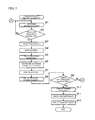
- FIG. 2 is a flow chart of the composite image creation processing. (Hereinafter, a step is referred to as "S" in the description of each processing.)
- the composite image creation processing is activated, for example, when an instruction for activating the composite image creation processing has been inputted through the operation input part 30, or when the vehicle has been put into reverse gear and started to move backward.
- the movement status determining part 61 acquires the movement information such as the detected value of the steering angle inputted from the steering sensor 10, the speed pulse signal inputted from the speed sensor 20, and the like, and determines, based on the acquired movement information, the movement status such as the movement distance and the turn angle of the vehicle using the distance parameter and the turn parameter recorded in the data recording part 70 (SA1).
- the composite image creating part 62 determines whether or not a timing to acquire the image data has been arrived based on the movement distance determined at SA1 (SA2). For example, the number of input pulses of the speed pulse signal is accumulated in a pulse counter stored in a RAM, when the accumulated number of pulses reaches a predetermined number, in other words, when it is supposed that the vehicle has moved by a predetermined distance, it is determined that the timing to acquire the image data has been arrived.
- the composite image creating part 62 acquires the image data imaged by the camera 40 (SA3). Then, the composite image creating part 62 resets a counter value of the pulse counter stored in the RAM and sets back to an initial value (SA4). Further, the overhead image creating part 63 performs an overhead conversion of the image data acquired by the composite image creating part 62 at SA3 to create recorded image data (SA5).
- the composite image creating part 62 determines the movement distance and the turn angle of the vehicle from a reference position (for example, a position of the vehicle when the composite image creation processing has been activated) based on the movement status such as the movement distance, the turn angle, and the like determined at SA1 (SA6). Based on the determined turn angle, the recorded image data created at SA5 is rotated in a generally-known image processing method (SA7). After that, based on the movement distance and the turn angle determined at SA6, the rotated recorded image data is recorded in a corresponding pixel range within an image composite range in the image memory 65 (SA8). If such pixel range is overlapped with the pixel range of the recorded image data created in previous times, the overlapped range is overwritten by the recorded image data imaged later.
- a reference position for example, a position of the vehicle when the composite image creation processing has been activated
- the composite image creating part 62 determines whether or not timing to output the composite image has been arrived (SA9). For example, if more than a predetermined number of recorded image data was recorded in the image memory 65 since the previous composite image output, it is determined that the timing to output the composite image has been arrived.
- the procedure returns to SA1 and the movement status determining part 61 performs determination of the movement status (SA1).
- the overhead image creating part 63 acquires the image data imaged by the camera 40 at such moment and performs the overhead conversion of such image data to create current image data (SA10).
- the composite image creating part 62 creates the composite image using the current image data created at SA10 and the recorded image data recorded in the image memory 65 (SA11). For example, the composite image creating part 62 extracts an area corresponding to a range including the current position of the vehicle from the respective recorded image data recorded in the image composite range and combines such extracted recorded image data with the current image data so as to be continuous by the same processing as each of SA6 to SA8 to create the composite image.
- the composite image creating part 62 displays the composite image on the display 50 (SA12). Thereafter, the processing of SA1 to SA12 is repeated.
- a termination trigger has been inputted (for example, when an instruction for terminating the composite image creation processing has been inputted through the operation input part 30, or when the vehicle has been put into a gear other than the reverse gear), the composite image creation processing is terminated.
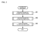
- FIG. 3 is a flow chart of the calibration processing.
- the calibration processing is activated for example when an operation input for starting the calibration processing has been received through the operation input part 30.
- the calibrating part 64 firstly executes overhead parameter calibration processing to calibrate the overhead parameter (SB1), secondly executes distance parameter calibration processing to calibrate the distance parameter (SB2), and finally executes turn parameter calibration processing to calibrate the turn parameter (SB3).
- SB1 overhead parameter calibration processing
- SB2 distance parameter calibration processing
- SB3 turn parameter calibration processing
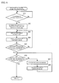
- FIG. 4 is a flow chart of the overhead parameter calibration processing.
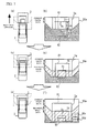
- FIGS. 5A and 5B show the vehicle and the display 50 at the time of execution of the overhead parameter calibration processing.
- FIG. 5A is a plain view showing the positions of the vehicle and a reference marker.
- FIG. 5B shows a display screen 50a of the display 50.
- the calibrating part 64 determines whether or not a reference marker 3 has been allocated on a road surface of an area that the camera 40 can image (SC1).
- the reference marker 3 is a marker that serves as a reference when calibrating a parameter, and can be configured with frame borders of a plurality of rectangles that overlap in one side, as shown in FIG. 5A .
- a first frame border 3a represents an external frame border in the reference marker 3
- the second frame border 3b represents an intermediate frame border
- the third frame border 3c represents an internal frame border.
- a "right-left frame border” represents a frame border parallel to the side on which the respective frame borders overlap each other
- a “forward-backward frame border” represents a frame border perpendicular to the right-left frame border. Note that after the reference marker has been allocated on the road surface, the position of the reference marker is virtually fixed on the road and does not move when the position of the vehicle changes.
- the reference marker 3 is allocated on the road surface or a vehicle 2 is moved so that the forward-backward frame border is parallel to a travel direction of the vehicle 2 and the side on which the respective frame borders of the reference marker 3 overlap each other matches a rear line of the vehicle 2 when viewing from a direction perpendicular above the vehicle 2. If the reference marker 3 is allocated in such manner and the operation input indicating that the allocation of the reference marker 3 was completed has been received through the operation input part 30 for example, it can be determined that the reference marker 3 was allocated on the road surface of the area that the camera 40 can image.
- the calibrating part 64 displays an overhead guide line on the display 50 based on the guide line information 71 stored in the data recording part 70 (SC 2).
- the overhead guide line indicates a predicted position of the reference marker 3 in the overhead image according to an overhead conversion, and serves as a reference when calibrating the overhead parameter based on the overhead image displayed on the display 50.
- an overhead guide line 80 is displayed as a frame border that indicates a position and a shape, in which manner the reference marker 3 should be displayed in the overhead image if the overhead parameter is correct.
- the overhead guide line 80 is superimposed and displayed as a bitmap image corresponding to the shape of the reference marker 3 over the overhead image on the display 50.
- the bitmap image of the overhead guide line 80 of which the position and the shape are determined for example using coordinate data in a coordinate system having an upper-left corner of the display screen 50a as an origin, is displayed fixedly on the display screen 50a.
- the overhead image creating part 63 creates the overhead image of the range including the position of the vehicle 2 based on the image data of the vicinity of the vehicle 2 imaged by the camera 40 and the overhead parameter, and displays the overhead image on the display 50 superimposing the overhead guide line 80 displayed at SC2 (SC3).
- SC3 SC2
- the overhead image creating part 63 refers to the overhead parameter recorded in the data recording part 70 and performs a coordinate conversion toward the image data inputted from the camera 40 to perform the overhead conversion toward such image data, and displays the converted image data on the display 50.
- the overhead image creating part 63 performs the overhead conversion toward the image data, which was acquired by imaging from an obliquely upward direction of the road surface where the reference marker 3 is allocated, and displays on the display 50 the converted image data as a plain view as shown in solid line in FIG. 5B .
- the calibrating part 64 determines whether or not the position of the reference marker 3 included in the overhead image that the overhead image creating part 63 created and displayed on the display 50 at SC3 matches the position of the overhead guide line 80 superimposed and displayed on the overhead image (SC4). If an input indicating that the position of the reference marker 3 included in the overhead image matches the position of the overhead guide line 80 has been performed for example by pressing an enter button (not shown) as the operation input part 30, the calibrating part 64 determines that the position of the reference marker 3 included in the overhead image matches the position of the overhead guide line 80. On the other hand, as shown in FIG.
- the calibrating part 64 changes a value of the overhead parameter recorded in the data recording part 70 for example based on the operation input through the operation input part 30 (SC5).
- SC5 the operation input part 30
- a button as the operation input part 30 is previously associated with a change volume of the overhead parameter to be changed if such button has been pressed, and based on the pressed button and the time of pressings, the change of the overhead parameter is performed by the corresponding change volume.
- the change of the overhead parameter is performed so that the overhead image is zoomed in (for example, a coordinate value to determine the installed position of the camera 40 is shifted to a coordinate value indicating a position higher than the position indicated by the current coordinate value, or a position anterior in relation to the vehicle 2).
- the change of the overhead parameter is performed so that the overhead image is zoomed out (for example, a coordinate value to determine the installed position of the camera 40 is shifted to a coordinate value indicating a position lower than the position indicated by the current coordinate value, or a position posterior in relation to the vehicle 2).
- the overhead image creating part 63 creates the overhead image using the overhead parameter after the change and displays the overhead image on the display 50 superimposing the overhead guide line 80 displayed at SC2 (SC3).
- the overhead image creating part 63 correctly performs the overhead conversion of the image data to create the overhead image and the calibrating part 64 terminates the overhead parameter calibration processing.
- FIG. 6 is a flow chart of the distance parameter calibration processing.
- FIGS. 7A to 7F show the vehicle 2 and the display 50 at the time of execution of the distance parameter calibration processing.
- FIGS. 7A, 7C, and 7E are plain views showing the positions of the vehicle 2 and the reference marker 3.
- FIGS. 7B, 7D, and 7F show the display screen 50a on the display 50.
- the densely-hatched range within the hatched range indicates the range where no image is displayed because there is no corresponding image data.
- the thinly-hatched range indicates the range composited based on the recorded image data recorded in the image memory 65 within the composite image.
- the distance parameter calibration processing is executed on the assumption that the reference marker 3 is allocated or the vehicle 2 is moved so that the forward-backward frame border of the reference marker 3 is parallel to the travel direction of the vehicle 2 and the side on which the respective frame borders of the reference marker 3 overlap each other matches a rear line of the vehicle 2 when viewing from a direction perpendicular above the vehicle 2 (refer to FIG. 7A ).
- the reference marker 3 is configured by combining a plurality of lines with a predetermined length by a predetermined angle each other.
- the reference marker 3 includes for example the first frame border 3a that is a square 1m 50cm on a side, the second frame border 3b that is a square 1m on a side, and the third frame border 3c that is a square 50cm on a side.
- the image of a fixed range having the vehicle 2 as a reference is displayed on the display 50.
- the range corresponding to the image is indicated in dashed line in FIGS. 7A, 7C, and 7E .
- the calibrating part 64 determines whether or not the reference marker 3 has been allocated on the road surface of the area that the camera 40 can image (SD1). For example, if the reference marker 3 is allocated as illustrated in FIG. 7A and the operation input indicating that the allocation of the reference marker 3 was completed has been received through the operation input part 30, it can be determined that the reference marker 3 has been allocated on the road surface of the area that the camera 40 can image. In this case, as shown in FIG. 7B , the overhead image created based on the actual image data imaged by the camera 40 is displayed as the current image data on the display screen 50a.
- the reference marker 3 is displayed so that the side on which the respective frame borders overlap each other is positioned at the lower part of the current image data (a border between non-hatched range and the hatched range in FIG. 7B ).
- the calibrating part 64 displays on the display 50 a position guide line and a distance guide line based on the guide line information 71 stored in the data recording part 70 (SD 2).
- the position guide line is a position marker as a reference to determine the position to stop when the vehicle 2 has moved straight, and displayed by a straight line perpendicular to the travel direction of the vehicle 2 on the display screen 50a. In the present embodiment, as shown in FIGS.
- a position guide line 81 is fixedly displayed at a position of the right-left frame border of the third frame border 3c of the reference marker 3 (the dotted line on the upper side in FIG. 7B ) in a condition before the vehicle 2 starts a straight backward movement ( FIG. 7B ).
- the position guide line 81 is fixedly displayed as the bitmap image indicating a straight line in a direction perpendicular to the travel direction of the vehicle 2 at a position corresponding to a distance of 50 cm from the lower part of the current image data in the composite image.
- the position guide line 81 is matched with the right-left frame border of the first frame border 3a that is 1m from the right-left frame guide line of the third frame border 3c of the reference marker 3.
- the position guide line 81 is displayed in a part of the current image data; therefore, whenever the vehicle 2 completes a 1m straight backward movement, the position guide line 81 becomes matched with the right-left frame border of the first frame border 3a.
- the bitmap image of the position guide line 81 of which the position and the shape are determined for example using the coordinate data in the coordinate system having the upper-left corner of the display screen 50a as an origin, is fixedly displayed on the display screen 50a.
- the distance guide line indicates a predicted position of the reference marker 3 in the composite image according to a straight movement, and serves as a reference when calibrating the distance parameter based on the composite image displayed on the display 50.
- a distance guide line 82 is fixedly displayed (the dotted line on the lower side in FIG. 7B ) at a part created based on the recorded image data imaged in the past within the composite image (a part where the "current image data" is not displayed in FIG.
- the distance parameter is correct, when the vehicle 2 has moved straight by a predetermined distance (in the present embodiment, 1m that corresponds to a distance from the right-left frame border of the third frame border 3c to the right-left frame border of the first frame border 3a of the reference marker 3).
- a predetermined distance in the present embodiment, 1m that corresponds to a distance from the right-left frame border of the third frame border 3c to the right-left frame border of the first frame border 3a of the reference marker 3.
- the distance guide line 82 is fixedly displayed as the bitmap image indicating a straight line in the direction perpendicular to the travel direction of the vehicle 2 at the position corresponding to the distance of 1m from the right-left frame border of the third frame border 3c in the composite image in the condition of FIG.7B , that is, the position corresponding to the distance of 50cm from a border between the current image data and the recorded image data. If the distance parameter is correct, when the vehicle 2 moves straight by 1m from the condition of FIG.
- the movement distance of the third frame border 3c in the composite image becomes equal to the actual movement distance 1m. Consequently, the distance guide line 82 matches the right-left frame border of the third frame border 3c displayed in the range of the recorded image data.
- the distance guide line 82 does not match the third frame border 3c displayed in the range of the recorded image data.
- the calibrating part 64 displays an instruction for moving the vehicle 2 straight backward toward the reference marker 3 on the display 50 (SD3). For example, the right-left frame border of the first frame border 3a and the position guide line 81 are highlighted, and a message indicating to move the vehicle 2 straight backward is displayed till these are matched. Or, it may be possible to automatically move the vehicle 2 straight backward by letting the calibrating part 64 control a throttle.
- the composite image creating part 62 executes the above-mentioned composite image creation processing to create the composite image of the range including the position of the vehicle 2 and displays the created composite image on the display 50 (SD4).
- the calibrating part 64 determines whether or not the position of the position guide line 81 displayed at SD2 matches the position of the reference marker 3 included in the composite image. (SD5). For example, in FIGS. 7A to 7F , if the right-left frame border of the first frame border 3a of the reference marker 3 is used as a reference, in case of the condition of FIG. 7D , it is determined that the positions of such frame border and the position guide line 81 are not matched. On the other hand, in case of the condition of FIG. 7F , it is determined that the positions of such frame border and the position guide line 81 are matched.
- the calibrating part 64 determines that the position of the position guide line 81 matches the position of the reference marker 3 included in the composite image. On the other hand, if the vehicle 2 continues the straight backward movement, the calibrating part 64 determines that the position of the position guide line 81 does not match the position of the reference marker 3 included in the composite image.
- the composite image creating part 62 repeats a creation of the composite image and its display on the display 50 (SD4).
- SD4 the composite image creating part 62 repeats a creation of the composite image and its display on the display 50 (SD4).
- the position of the position guide line 81 matches the position of the reference marker 3 included in the composite image (SD5: YES)
- the calibrating part 64 determines whether or not the position of the reference marker 3 included in the composite image that the composite image creating part 62 created according to the straight movement of the vehicle 2 matches the position of the distance guide line 82 superimposed and displayed on the composite image (SD6). If an input indicating that the positions of the third frame border 3c of the reference marker 3 in the composite image and the distance guide line 82 are matched is performed for example by pressing an enter button (not shown) as the operation input part 30, the calibrating part 64 determines that the position of the distance guide line 82 matches the position of the reference marker 3 included in the composite image.
- FIGS. 7A to 7F if the right-left frame border of the third frame border 3c of the reference marker 3 is used as a reference, in case of the condition of FIG. 7F , it is determined that the positions of such frame border and the distance guide line 82 are not matched. , For example, if a radius of tires was enlarged due to a change of tires, the distance that the vehicle 2 actually moves per pulse of the speed pulse signal becomes longer than the distance to move per pulse of the speed pulse signal that is recorded as the distance parameter in the data recording part 70.
- the composite image is created based on the movement distance determined in such manner in the composite image creation processing, the composite image, in which the right-left frame border of the third frame border 3c does not reach the distance guide line 82, is created as shown in FIG. 7F .
- the calibrating part 64 changes a value of the distance parameter recorded in the data recording part 70, for example, based on the operation input through the operation input part 30 (SD7).
- SD7 the operation input through the operation input part 30
- the "up" button 30c and the "down” button 30d are displayed as operation input buttons for changing the distance parameter on the display 50 serving as a touch panel. If the "up" button 30c has been operated, the distance parameter is changed so that the reference marker 3 displayed in the part of the recorded image data within the composite image is moved upward on the display screen 50a.
- the distance to move per pulse of the speed pulse signal recorded as the distance parameter in the data recording part 70 is shifted to a value smaller than a current value. For example, each time the "up" button 30c is pressed once, the distance to move per pulse of the speed pulse signal is shortened by a predetermined length (for example 1cm). On the other hand, if the "down" button 30d has been operated, the distance parameter is changed so that the reference marker 3 displayed in the part of the recorded image data within the composite image is moved downward on the display screen 50a.
- the distance to move per pulse of the speed pulse signal recorded as the distance parameter in the data recording part 70 is shifted to a value larger than a current value. For example, each time the "down" button 30d is pressed once, the distance to move per pulse of the speed pulse signal is enlarged by a predetermined length (for example 1cm).
- the composite image creating part 62 executes the composite image creation processing using the distance parameter after the change and displays the created composite image on the display 50 superimposing the position guide line 81 and the distance guide line 82 displayed at SD2 (SD8). Then, it is determined that the position of the reference marker 3 included in the composite image matches the position of the distance guide line 82 again (SD6).
- FIG. 8 is a flow chart of the turn parameter calibration processing.
- FIGS. 9A to 9F show the vehicle 2 and the display 50 at the time of execution of the turn parameter calibration processing.
- FIGS. 9A, 9C, and 9E are plain views showing the positions of the vehicle 2 and the reference marker 3.
- FIGS. 9B, 9D, and 9F show the display screen 50a on the display 50.
- the turn parameter calibration processing is executed on the assumption that the reference marker 3 is allocated in the vicinity of a rear side of the vehicle 2 so that the forward-backward frame border of the reference marker 3 is parallel to the travel direction of the vehicle 2 (refer to FIG. 9A ).
- the calibrating part 64 determines whether or not the reference marker 3 has been allocated on the road surface of the area that the camera 40 can image (SE1). For example, if the reference marker 3 is allocated as illustrated in FIG. 9A and the operation input indicating that the allocation of the reference marker 3 was completed has been received through the operation input part 30, it can be determined that the reference marker 3 has been allocated on the road surface of the area that the camera 40 can image.
- the calibrating part 64 displays a turn guide line on the display 50 based on the guide line information 71 stored in the data recording part 70 (SE 2).
- the turn guide line indicates a predicted position of the reference marker 3 in the composite image according to a turn, and serves as a reference when calibrating the turn parameter based on the composite image displayed on the display 50.
- the predicted position of the forward-backward frame border of the first frame border 3a of the reference marker 3 of when the vehicle 2 moves backward by a predetermined distance with a predefined steering angle from the condition, in which the reference marker 3 was positioned in the vicinity of the rear side of the vehicle 2, as shown in FIG. 9A is determined using the turn parameter recorded in the data recording part 70 and displayed as the turn guide line 83.
- the calibrating part 64 displays an instruction for turning the vehicle 2 on the display 50 (SE3). For example, a message indicating to turn a steering wheel by a predetermined steering angle (for example, turn one rotation in a counterclockwise direction or the like) and a distance counter for moving the vehicle backward by a predetermined distance (for example, move backward 1m more, or the like) are displayed on the display 50. Or, it may be possible to automatically turn the vehicle 2 by letting the calibrating part 64 control a steering wheel and a throttle.
- a predetermined steering angle for example, turn one rotation in a counterclockwise direction or the like
- a distance counter for moving the vehicle backward by a predetermined distance for example, move backward 1m more, or the like
- the composite image creating part 62 executes the above-mentioned composite image creation processing to create the composite image of the range including the position of the vehicle 2 and displays the created composite image on the display 50 (SE4).
- the calibrating part 64 determines whether or not the vehicle 2 has moved backward by a predetermined distance (SE5). For example, based on the vehicle speed pulse signal inputted from the speed sensor 20 and the distance parameter calibrated in the distance parameter calibration processing, the movement status determining part 61 determines the movement distance of the vehicle 2 and determines whether or not the determined movement distance has reached a predetermined distance. As the result, if it is determined that the vehicle 2 has not moved backward by the predetermined distance (SE5: NO), the calibrating part 64 returns to SE3 and displays the instruction for turning the vehicle 2 on the display 50.
- SE5 a predetermined distance
- the calibrating part 64 determines whether or not the position of the reference marker 3 included in the composite image that the composite image creating part 62 created according to the turn of the vehicle 2 matches the position of the turn guide line 83 superimposed and displayed on the composite image (SE6).
- FIG. 9F showing the display screen 50a of the display 50 of when the vehicle 2 has moved backward by the predetermined distance
- the positions of the forward-backward frame border of the first frame border 3a of the reference marker 3 and the turn guide line 83 as the predicted position thereof are not matched.
- the actual turning radius corresponding to the steering angle on the vehicle 2 becomes larger than the turning radius recorded as the turn parameter in the data recording part 70.
- the turn angle when the vehicle has moved by the predetermined distance becomes small.
- the angle between recorded image data, which is turned and overlaid sequentially according to the turn of the vehicle 2 becomes larger than the actual turn angle of the vehicle 2. Consequently, the forward-backward frame border of the third frame border 3c is curved, and the composite image, in which the position of forward-backward frame border of the third frame border 3c does not match the position of the turn guide line 83, is created as shown in FIG. 9F .
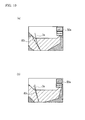
- FIGS. 10A and 10B illustrate the display screen 50a displayed on the display 50 when changing the value of the turn parameter.
- FIG. 10A shows the display screen 50a before a change of the turn parameter.
- FIG. 10B shows the display screen 50a after the change of the turn parameter.
- a "left" button 30e and a “right” button 30f are displayed as operation input buttons for changing the turn parameter on the display 50 serving as a touch panel. If the "left" button 30e has been operated, the turn parameter is changed so that the reference marker 3 displayed in the part of the recorded image data among the turn guide line 83 and the composite image is turned in a counterclockwise direction on the display screen 50a. That is, in order to reduce the turn angle of the recorded image data overlaid sequentially along with the turn of the vehicle 2 in the composite image creation processing, the turning radius recorded as the turn parameter in the data recording part 70 is shifted to a value larger than a current value.
- the turn parameter is changed so that the reference marker 3 displayed in the part of the recorded image data among the turn guide line 83 and the composite image is turned in a clockwise direction on the display screen 50a. That is, in order to increase the turn angle of the recorded image data overlaid sequentially along with the turn of the vehicle 2 in the composite image creation processing, the turning radius recorded as the turn parameter in the data recording part 70 is shifted to a value smaller than a current value.
- the calibrating part 64 determines the predicted position of the forward-backward frame border of the reference border 3 using the turn parameter after the change again, and displays the determined predicted position as the turn guide line 83 after the change on the display 50 (SE8). For example, in the processing at SE7, if shifting the turning radius recorded as the turn parameter to a value larger than the current value, the turn angle of the recorded image data rotated and overlaid sequentially along with the turn of the vehicle 2 is reduced. As the result, the turn guide line 83 on the display screen 50a indicated in FIG. 10B is re-allocated as a straight line along the travel direction of the vehicle 2 (an up-down direction on the display screen 50a) more compared to the turn guide line 83 on the display screen 50a indicated in FIG. 10A .
- the composite image creating part 62 executes the composite creation processing using the turn parameter after the change, and displays the created composite image on the display 50 superimposing the turn guide line 83 displayed at SE8 (SE9).
- SE9 the composite image creating part 62 executes the composite creation processing using the turn parameter after the change, and displays the created composite image on the display 50 superimposing the turn guide line 83 displayed at SE8 (SE9).
- SE7 if shifting the turning radius recorded as the turn parameter to a value larger than the current value, the forward-backward frame border of the first frame border 3a of the reference marker 3 on the display screen 50a indicated in FIG. 10B is less curved than the same frame border on the display screen 50a indicated in FIG. 10A , and displayed as a line along the turn guide line 83.
- the turn parameter which the movement status determining part 61 uses in determining a turn as the movement status based on the movement information, is calibrated.
- the turn parameter can be calibrated based on a difference between the position of the reference marker 3 in the composite image and the predicted position thereof, and a precise composite image can be displayed by compositing the image data recorded in the data recording part 70 using the calibrated turn parameter.
- the distance parameter which the movement status determining part 61 uses in determining a movement distance as the movement status based on the movement information, is calibrated.
- the distance parameter can be calibrated based on the difference between the position of the reference marker 3 in the composite image and the predicted position thereof, and a precise composite image can be displayed by compositing the image data recorded in the data recording part 70 using the calibrated distance parameter.
- the overhead parameter which the overhead image creating part 63 uses in creating the overhead image, is calibrated. Consequently, even if a precise overhead image cannot be displayed using the overhead parameter due to a deviation of the installed position of the camera 40 or the like, the overhead parameter can be calibrated based on the difference between the position of the reference marker 3 in the composite image and the predicted position thereof, and a precise overhead image can be created using the calibrated overhead parameter.
- a position marker corresponding to the position of the vehicle 2 is displayed in a part created based on the actual image data imaged by the camera 40 within the composite image that the composite image creating part 62 creates. Therefore, a target position when moving the vehicle 2 by the predetermined distance can be presented based on such position marker, regardless of whether or not the part created based on the recorded image data within the composite image is precise.
- the distance parameter is preferably calibrated after the overhead parameter was calibrated; therefore, the distance parameter can be calibrated based on the position guide line 81 and the distance guide line 82 displayed in a precise overhead image.
- the turn parameter is preferably calibrated after the distance parameter was calibrated; therefore, the turn parameter can be calibrated based on the composite image and the turn guide line 83 created using the correct distance parameter.
- the order of the different calibration steps can be interchanged.
- the reference marker 3 used in each processing of calibration processing is configured with the frame borders of a plurality of rectangles that overlap in one side.
- different reference markers can be used in each processing.
- the overhead parameter calibration processing only the first frame border 3a is used.
- the distance parameter calibration processing only the right-left frame borders of the first frame border 3a and the third frame border 3c may be used.
- the forward-backward frame border of the first frame border 3a may be used.
Landscapes
- Engineering & Computer Science (AREA)
- General Physics & Mathematics (AREA)
- Theoretical Computer Science (AREA)
- Physics & Mathematics (AREA)
- Multimedia (AREA)
- Computer Vision & Pattern Recognition (AREA)
- Closed-Circuit Television Systems (AREA)
- Image Processing (AREA)
- Fittings On The Vehicle Exterior For Carrying Loads, And Devices For Holding Or Mounting Articles (AREA)
- Length Measuring Devices By Optical Means (AREA)
- Traffic Control Systems (AREA)
- Studio Devices (AREA)
- Time Recorders, Dirve Recorders, Access Control (AREA)
Applications Claiming Priority (1)
| Application Number | Priority Date | Filing Date | Title |
|---|---|---|---|
| JP2009080008A JP4831374B2 (ja) | 2009-03-27 | 2009-03-27 | 運転支援装置、運転支援方法、及び運転支援プログラム |
Publications (3)
| Publication Number | Publication Date |
|---|---|
| EP2233357A2 true EP2233357A2 (fr) | 2010-09-29 |
| EP2233357A3 EP2233357A3 (fr) | 2012-06-13 |
| EP2233357B1 EP2233357B1 (fr) | 2013-11-20 |
Family
ID=42309613
Family Applications (1)
| Application Number | Title | Priority Date | Filing Date |
|---|---|---|---|
| EP10001227.7A Not-in-force EP2233357B1 (fr) | 2009-03-27 | 2010-02-05 | Dispositif de support de commande, procédé de support de commande, et programme de support de commande |
Country Status (4)
| Country | Link |
|---|---|
| US (1) | US8675070B2 (fr) |
| EP (1) | EP2233357B1 (fr) |
| JP (1) | JP4831374B2 (fr) |
| CN (1) | CN101848370B (fr) |
Cited By (2)
| Publication number | Priority date | Publication date | Assignee | Title |
|---|---|---|---|---|
| EP2535869A3 (fr) * | 2011-06-13 | 2013-12-25 | Alpine Electronics, Inc. | Appareil et procédé pour détection de la posture d'une camera montée sur véhicule |
| EP3032818A4 (fr) * | 2013-08-08 | 2016-07-27 | Panasonic Ip Man Co Ltd | Dispositif de traitement d'image et marqueurs |
Families Citing this family (28)
| Publication number | Priority date | Publication date | Assignee | Title |
|---|---|---|---|---|
| WO2012035886A1 (fr) * | 2010-09-16 | 2012-03-22 | パイオニア株式会社 | Dispositif de maintien de terminal |
| US9064296B2 (en) * | 2010-10-22 | 2015-06-23 | Pioneer Corporation | Terminal device, image processing method and image processing program executed by a terminal device |
| JP5858045B2 (ja) * | 2011-09-13 | 2016-02-10 | トヨタ自動車株式会社 | 車載カメラの光軸把握装置 |
| JP5750344B2 (ja) * | 2011-09-16 | 2015-07-22 | 日立建機株式会社 | 作業機の周囲監視装置 |
| US9760092B2 (en) | 2012-03-16 | 2017-09-12 | Waymo Llc | Actively modifying a field of view of an autonomous vehicle in view of constraints |
| JP6025365B2 (ja) * | 2012-04-04 | 2016-11-16 | 京セラ株式会社 | 較正処理装置、カメラ較正装置、カメラシステム、およびカメラ較正方法 |
| CN103369216A (zh) * | 2012-04-06 | 2013-10-23 | 英华达(上海)科技有限公司 | 摄像装置及其校正拍摄范围的方法 |
| JP5888087B2 (ja) | 2012-04-25 | 2016-03-16 | ソニー株式会社 | 走行支援画像生成装置、走行支援画像生成方法、車載用カメラおよび機器操縦支援画像生成装置 |
| JP5820787B2 (ja) | 2012-08-30 | 2015-11-24 | 株式会社デンソー | 画像処理装置、及びプログラム |
| JP5923422B2 (ja) * | 2012-09-24 | 2016-05-24 | クラリオン株式会社 | カメラのキャリブレーション方法及び装置 |
| US20140176709A1 (en) * | 2012-12-21 | 2014-06-26 | Caterpillar, Inc. | Video Overlays for RC/Autonomous Machine |
| DE102013015847B3 (de) * | 2013-09-24 | 2015-03-05 | Mekra Lang Gmbh & Co. Kg | Sichtsystem |
| US20140232871A1 (en) * | 2014-05-01 | 2014-08-21 | Caterpillar Inc. | Method for manually calibrating a camera mounted on vehicle |
| JP6327160B2 (ja) * | 2014-09-02 | 2018-05-23 | 株式会社デンソー | 車両用画像処理装置 |
| WO2016035271A1 (fr) * | 2014-09-02 | 2016-03-10 | 株式会社デンソー | Dispositif de traitement d'image pour véhicule |
| JP6466139B2 (ja) * | 2014-10-20 | 2019-02-06 | 有限会社テレビジネス | 人間の動きを測定するロボット計測器 |
| JP2017139612A (ja) * | 2016-02-03 | 2017-08-10 | パナソニックIpマネジメント株式会社 | 車載カメラ用校正システム |
| JP6337126B2 (ja) * | 2016-03-28 | 2018-06-06 | 株式会社小松製作所 | 評価装置及びコンピュータプログラム |
| JP6642306B2 (ja) * | 2016-06-29 | 2020-02-05 | アイシン精機株式会社 | 周辺監視装置 |
| DE102017130173A1 (de) * | 2017-02-24 | 2018-08-30 | Denso Ten Limited | Ladeunterstützungsvorrichtung |
| CN108028911B (zh) * | 2017-06-28 | 2021-09-28 | 株式会社小松制作所 | 作业机械的显示装置及显示系统 |
| WO2019026348A1 (fr) * | 2017-07-31 | 2019-02-07 | 株式会社Jvcケンウッド | Dispositif de commande d'affichage, système de commande d'affichage, procédé de commande d'affichage, et programme |
| US10748032B1 (en) * | 2019-01-31 | 2020-08-18 | StradVision, Inc. | Method for providing robust object distance estimation based on camera by performing pitch calibration of camera more precisely with fusion of information acquired through camera and information acquired through V2V communication and device using the same |
| US10872532B2 (en) * | 2019-02-27 | 2020-12-22 | ANI Technologies Private Limited | Calibration of fixed image-capturing device for predicting driving lane |
| US20230061195A1 (en) * | 2021-08-27 | 2023-03-02 | Continental Automotive Systems, Inc. | Enhanced transparent trailer |
| US20230311769A1 (en) * | 2022-03-31 | 2023-10-05 | Cnh Industrial America Llc | System and method for an agricultural applicator |
| US12043242B2 (en) * | 2022-05-23 | 2024-07-23 | Waymo Llc | Repositioning rooftop sensors for autonomous vehicles |
| JP7611282B2 (ja) * | 2023-03-13 | 2025-01-09 | 株式会社慶洋エンジニアリング | 後方物体確認装置及び後方物体確認システム |
Citations (1)
| Publication number | Priority date | Publication date | Assignee | Title |
|---|---|---|---|---|
| JP2008205928A (ja) | 2007-02-21 | 2008-09-04 | Sanyo Electric Co Ltd | 運転支援システム |
Family Cites Families (13)
| Publication number | Priority date | Publication date | Assignee | Title |
|---|---|---|---|---|
| JP2002135765A (ja) * | 1998-07-31 | 2002-05-10 | Matsushita Electric Ind Co Ltd | カメラキャリブレーション指示装置及びカメラキャリブレーション装置 |
| JP2000225970A (ja) * | 1998-11-30 | 2000-08-15 | Tuner Kk | 車載用画像記録システム |
| US6813371B2 (en) * | 1999-12-24 | 2004-11-02 | Aisin Seiki Kabushiki Kaisha | On-vehicle camera calibration device |
| JP3551920B2 (ja) * | 1999-12-24 | 2004-08-11 | アイシン精機株式会社 | 車載カメラの校正装置および校正方法 |
| US20020052724A1 (en) * | 2000-10-23 | 2002-05-02 | Sheridan Thomas B. | Hybrid vehicle operations simulator |
| JP2003044996A (ja) * | 2001-07-31 | 2003-02-14 | Matsushita Electric Ind Co Ltd | 障害物検出装置 |
| EP1637836A1 (fr) * | 2003-05-29 | 2006-03-22 | Olympus Corporation | Dispositif et procede de support de camera stereo, dispositif et procede de detection d'etalonnage, et systeme de camera stereo |
| JP2004354236A (ja) | 2003-05-29 | 2004-12-16 | Olympus Corp | ステレオカメラ支持装置およびステレオカメラ支持方法ならびにステレオカメラシステム |
| JP3916240B2 (ja) * | 2003-08-07 | 2007-05-16 | 松下電器産業株式会社 | 運転支援装置及び運転支援方法 |
| JP4238663B2 (ja) * | 2003-08-29 | 2009-03-18 | トヨタ自動車株式会社 | 車載カメラのキャリブレーション方法及びキャリブレーション装置 |
| JP4868964B2 (ja) * | 2006-07-13 | 2012-02-01 | 三菱ふそうトラック・バス株式会社 | 走行状態判定装置 |
| JP4863922B2 (ja) * | 2007-04-18 | 2012-01-25 | 三洋電機株式会社 | 運転支援システム並びに車両 |
| AU2009211435A1 (en) * | 2008-02-04 | 2009-08-13 | Tele Atlas B.V. | Method for map matching with sensor detected objects |
-
2009
- 2009-03-27 JP JP2009080008A patent/JP4831374B2/ja not_active Expired - Fee Related
-
2010
- 2010-02-05 EP EP10001227.7A patent/EP2233357B1/fr not_active Not-in-force
- 2010-02-05 US US12/700,965 patent/US8675070B2/en not_active Expired - Fee Related
- 2010-02-11 CN CN201010117713.8A patent/CN101848370B/zh not_active Expired - Fee Related
Patent Citations (1)
| Publication number | Priority date | Publication date | Assignee | Title |
|---|---|---|---|---|
| JP2008205928A (ja) | 2007-02-21 | 2008-09-04 | Sanyo Electric Co Ltd | 運転支援システム |
Cited By (4)
| Publication number | Priority date | Publication date | Assignee | Title |
|---|---|---|---|---|
| EP2535869A3 (fr) * | 2011-06-13 | 2013-12-25 | Alpine Electronics, Inc. | Appareil et procédé pour détection de la posture d'une camera montée sur véhicule |
| US9361687B2 (en) | 2011-06-13 | 2016-06-07 | Alpine Electronics, Inc. | Apparatus and method for detecting posture of camera mounted on vehicle |
| EP3032818A4 (fr) * | 2013-08-08 | 2016-07-27 | Panasonic Ip Man Co Ltd | Dispositif de traitement d'image et marqueurs |
| US10165262B2 (en) | 2013-08-08 | 2018-12-25 | Panasonic Intellectual Property Management Co., Ltd. | Image processing device and markers |
Also Published As
| Publication number | Publication date |
|---|---|
| CN101848370A (zh) | 2010-09-29 |
| EP2233357B1 (fr) | 2013-11-20 |
| JP2010233079A (ja) | 2010-10-14 |
| EP2233357A3 (fr) | 2012-06-13 |
| JP4831374B2 (ja) | 2011-12-07 |
| US8675070B2 (en) | 2014-03-18 |
| US20100245575A1 (en) | 2010-09-30 |
| CN101848370B (zh) | 2014-09-24 |
Similar Documents
| Publication | Publication Date | Title |
|---|---|---|
| EP2233357B1 (fr) | Dispositif de support de commande, procédé de support de commande, et programme de support de commande | |
| JP5316805B2 (ja) | 車載カメラ装置の画像調整装置及び車載カメラ装置 | |
| EP2464113B1 (fr) | Dispositif de génération d'images périphériques du véhicule | |
| CN104956668B (zh) | 图像处理装置以及图像处理方法 | |
| CN114423646B (zh) | 基于传感器融合的感知增强环绕视图 | |
| JP4877447B2 (ja) | 車両周辺画像表示装置 | |
| WO2001058164A1 (fr) | Ecran de proximite pour vehicule automobile | |
| US20160309082A1 (en) | Method and Device for Panoramic Image Processing | |
| JP5914013B2 (ja) | 運転支援装置 | |
| US20120293659A1 (en) | Parameter determining device, parameter determining system, parameter determining method, and recording medium | |
| JP2008239148A (ja) | 車両用表示装置及び車両表示システム並びに車両 | |
| JP2016141246A (ja) | ミラー制御装置及びミラー制御システム | |
| JP4436392B2 (ja) | 映像処理装置 | |
| JP2010108185A (ja) | 表示制御システム、表示制御方法、及び表示制御プログラム | |
| JP4496503B2 (ja) | 車両用運転支援装置 | |
| JP2008307981A (ja) | 車両用運転支援装置 | |
| JP2012049700A (ja) | 車両周辺監視装置 | |
| JP4317046B2 (ja) | 駐車支援システム | |
| JP2011118485A (ja) | 方向転換支援装置及び方法 | |
| JP2012188057A (ja) | 表示装置 | |
| JP5077286B2 (ja) | 車両周辺画像表示装置 | |
| CN116915944A (zh) | 显示控制装置、显示装置及车辆 | |
| KR101659606B1 (ko) | 뒷바퀴 위치 표시 차량 후진 영상 시스템의 영상 표시 방법 | |
| JP2020082977A (ja) | 駐車支援システムおよび駐車支援方法 | |
| JP6520508B2 (ja) | 産業車両の表示システム |
Legal Events
| Date | Code | Title | Description |
|---|---|---|---|
| PUAI | Public reference made under article 153(3) epc to a published international application that has entered the european phase |
Free format text: ORIGINAL CODE: 0009012 |
|
| AK | Designated contracting states |
Kind code of ref document: A2 Designated state(s): AT BE BG CH CY CZ DE DK EE ES FI FR GB GR HR HU IE IS IT LI LT LU LV MC MK MT NL NO PL PT RO SE SI SK SM TR |
|
| AX | Request for extension of the european patent |
Extension state: AL BA RS |
|
| PUAL | Search report despatched |
Free format text: ORIGINAL CODE: 0009013 |
|
| AK | Designated contracting states |
Kind code of ref document: A3 Designated state(s): AT BE BG CH CY CZ DE DK EE ES FI FR GB GR HR HU IE IS IT LI LT LU LV MC MK MT NL NO PL PT RO SE SI SK SM TR |
|
| AX | Request for extension of the european patent |
Extension state: AL BA RS |
|
| RIC1 | Information provided on ipc code assigned before grant |
Ipc: G06T 7/00 20060101ALI20120510BHEP Ipc: B60R 1/00 20060101AFI20120510BHEP Ipc: G06K 9/20 20060101ALI20120510BHEP Ipc: G06K 9/00 20060101ALI20120510BHEP |
|
| 17P | Request for examination filed |
Effective date: 20121211 |
|
| GRAP | Despatch of communication of intention to grant a patent |
Free format text: ORIGINAL CODE: EPIDOSNIGR1 |
|
| RIC1 | Information provided on ipc code assigned before grant |
Ipc: G06K 9/00 20060101ALI20130603BHEP Ipc: G06T 7/00 20060101ALI20130603BHEP Ipc: B60R 1/00 20060101AFI20130603BHEP Ipc: G06K 9/20 20060101ALI20130603BHEP |
|
| INTG | Intention to grant announced |
Effective date: 20130708 |
|
| GRAS | Grant fee paid |
Free format text: ORIGINAL CODE: EPIDOSNIGR3 |
|
| GRAA | (expected) grant |
Free format text: ORIGINAL CODE: 0009210 |
|
| AK | Designated contracting states |
Kind code of ref document: B1 Designated state(s): AT BE BG CH CY CZ DE DK EE ES FI FR GB GR HR HU IE IS IT LI LT LU LV MC MK MT NL NO PL PT RO SE SI SK SM TR |
|
| REG | Reference to a national code |
Ref country code: GB Ref legal event code: FG4D |
|
| REG | Reference to a national code |
Ref country code: CH Ref legal event code: EP |
|
| REG | Reference to a national code |
Ref country code: AT Ref legal event code: REF Ref document number: 641383 Country of ref document: AT Kind code of ref document: T Effective date: 20131215 |
|
| REG | Reference to a national code |
Ref country code: IE Ref legal event code: FG4D |
|
| REG | Reference to a national code |
Ref country code: DE Ref legal event code: R096 Ref document number: 602010011796 Country of ref document: DE Effective date: 20140116 |
|
| REG | Reference to a national code |
Ref country code: NL Ref legal event code: VDEP Effective date: 20131120 |
|
| REG | Reference to a national code |
Ref country code: AT Ref legal event code: MK05 Ref document number: 641383 Country of ref document: AT Kind code of ref document: T Effective date: 20131120 |
|
| REG | Reference to a national code |
Ref country code: LT Ref legal event code: MG4D |
|
| PG25 | Lapsed in a contracting state [announced via postgrant information from national office to epo] |
Ref country code: HR Free format text: LAPSE BECAUSE OF FAILURE TO SUBMIT A TRANSLATION OF THE DESCRIPTION OR TO PAY THE FEE WITHIN THE PRESCRIBED TIME-LIMIT Effective date: 20131120 Ref country code: NO Free format text: LAPSE BECAUSE OF FAILURE TO SUBMIT A TRANSLATION OF THE DESCRIPTION OR TO PAY THE FEE WITHIN THE PRESCRIBED TIME-LIMIT Effective date: 20140220 Ref country code: FI Free format text: LAPSE BECAUSE OF FAILURE TO SUBMIT A TRANSLATION OF THE DESCRIPTION OR TO PAY THE FEE WITHIN THE PRESCRIBED TIME-LIMIT Effective date: 20131120 Ref country code: LT Free format text: LAPSE BECAUSE OF FAILURE TO SUBMIT A TRANSLATION OF THE DESCRIPTION OR TO PAY THE FEE WITHIN THE PRESCRIBED TIME-LIMIT Effective date: 20131120 Ref country code: IS Free format text: LAPSE BECAUSE OF FAILURE TO SUBMIT A TRANSLATION OF THE DESCRIPTION OR TO PAY THE FEE WITHIN THE PRESCRIBED TIME-LIMIT Effective date: 20140320 Ref country code: NL Free format text: LAPSE BECAUSE OF FAILURE TO SUBMIT A TRANSLATION OF THE DESCRIPTION OR TO PAY THE FEE WITHIN THE PRESCRIBED TIME-LIMIT Effective date: 20131120 Ref country code: SE Free format text: LAPSE BECAUSE OF FAILURE TO SUBMIT A TRANSLATION OF THE DESCRIPTION OR TO PAY THE FEE WITHIN THE PRESCRIBED TIME-LIMIT Effective date: 20131120 |
|
| PG25 | Lapsed in a contracting state [announced via postgrant information from national office to epo] |
Ref country code: BE Free format text: LAPSE BECAUSE OF FAILURE TO SUBMIT A TRANSLATION OF THE DESCRIPTION OR TO PAY THE FEE WITHIN THE PRESCRIBED TIME-LIMIT Effective date: 20131120 Ref country code: AT Free format text: LAPSE BECAUSE OF FAILURE TO SUBMIT A TRANSLATION OF THE DESCRIPTION OR TO PAY THE FEE WITHIN THE PRESCRIBED TIME-LIMIT Effective date: 20131120 Ref country code: ES Free format text: LAPSE BECAUSE OF FAILURE TO SUBMIT A TRANSLATION OF THE DESCRIPTION OR TO PAY THE FEE WITHIN THE PRESCRIBED TIME-LIMIT Effective date: 20131120 Ref country code: LV Free format text: LAPSE BECAUSE OF FAILURE TO SUBMIT A TRANSLATION OF THE DESCRIPTION OR TO PAY THE FEE WITHIN THE PRESCRIBED TIME-LIMIT Effective date: 20131120 |
|
| PG25 | Lapsed in a contracting state [announced via postgrant information from national office to epo] |
Ref country code: PT Free format text: LAPSE BECAUSE OF FAILURE TO SUBMIT A TRANSLATION OF THE DESCRIPTION OR TO PAY THE FEE WITHIN THE PRESCRIBED TIME-LIMIT Effective date: 20140320 |
|
| PG25 | Lapsed in a contracting state [announced via postgrant information from national office to epo] |
Ref country code: EE Free format text: LAPSE BECAUSE OF FAILURE TO SUBMIT A TRANSLATION OF THE DESCRIPTION OR TO PAY THE FEE WITHIN THE PRESCRIBED TIME-LIMIT Effective date: 20131120 |
|
| REG | Reference to a national code |
Ref country code: DE Ref legal event code: R097 Ref document number: 602010011796 Country of ref document: DE |
|
| PG25 | Lapsed in a contracting state [announced via postgrant information from national office to epo] |
Ref country code: SK Free format text: LAPSE BECAUSE OF FAILURE TO SUBMIT A TRANSLATION OF THE DESCRIPTION OR TO PAY THE FEE WITHIN THE PRESCRIBED TIME-LIMIT Effective date: 20131120 Ref country code: CZ Free format text: LAPSE BECAUSE OF FAILURE TO SUBMIT A TRANSLATION OF THE DESCRIPTION OR TO PAY THE FEE WITHIN THE PRESCRIBED TIME-LIMIT Effective date: 20131120 Ref country code: PL Free format text: LAPSE BECAUSE OF FAILURE TO SUBMIT A TRANSLATION OF THE DESCRIPTION OR TO PAY THE FEE WITHIN THE PRESCRIBED TIME-LIMIT Effective date: 20131120 Ref country code: RO Free format text: LAPSE BECAUSE OF FAILURE TO SUBMIT A TRANSLATION OF THE DESCRIPTION OR TO PAY THE FEE WITHIN THE PRESCRIBED TIME-LIMIT Effective date: 20131120 |
|
| PLBE | No opposition filed within time limit |
Free format text: ORIGINAL CODE: 0009261 |
|
| STAA | Information on the status of an ep patent application or granted ep patent |
Free format text: STATUS: NO OPPOSITION FILED WITHIN TIME LIMIT |
|
| PG25 | Lapsed in a contracting state [announced via postgrant information from national office to epo] |
Ref country code: DK Free format text: LAPSE BECAUSE OF FAILURE TO SUBMIT A TRANSLATION OF THE DESCRIPTION OR TO PAY THE FEE WITHIN THE PRESCRIBED TIME-LIMIT Effective date: 20131120 Ref country code: MC Free format text: LAPSE BECAUSE OF FAILURE TO SUBMIT A TRANSLATION OF THE DESCRIPTION OR TO PAY THE FEE WITHIN THE PRESCRIBED TIME-LIMIT Effective date: 20131120 Ref country code: LU Free format text: LAPSE BECAUSE OF FAILURE TO SUBMIT A TRANSLATION OF THE DESCRIPTION OR TO PAY THE FEE WITHIN THE PRESCRIBED TIME-LIMIT Effective date: 20140205 |
|
| REG | Reference to a national code |
Ref country code: CH Ref legal event code: PL |
|
| 26N | No opposition filed |
Effective date: 20140821 |
|
| PG25 | Lapsed in a contracting state [announced via postgrant information from national office to epo] |
Ref country code: LI Free format text: LAPSE BECAUSE OF NON-PAYMENT OF DUE FEES Effective date: 20140228 Ref country code: CH Free format text: LAPSE BECAUSE OF NON-PAYMENT OF DUE FEES Effective date: 20140228 |
|
| REG | Reference to a national code |
Ref country code: IE Ref legal event code: MM4A |
|
| REG | Reference to a national code |
Ref country code: DE Ref legal event code: R097 Ref document number: 602010011796 Country of ref document: DE Effective date: 20140821 |
|
| PG25 | Lapsed in a contracting state [announced via postgrant information from national office to epo] |
Ref country code: IE Free format text: LAPSE BECAUSE OF NON-PAYMENT OF DUE FEES Effective date: 20140205 |
|
| REG | Reference to a national code |
Ref country code: FR Ref legal event code: PLFP Year of fee payment: 6 |
|
| PG25 | Lapsed in a contracting state [announced via postgrant information from national office to epo] |
Ref country code: SI Free format text: LAPSE BECAUSE OF FAILURE TO SUBMIT A TRANSLATION OF THE DESCRIPTION OR TO PAY THE FEE WITHIN THE PRESCRIBED TIME-LIMIT Effective date: 20131120 |
|
| PG25 | Lapsed in a contracting state [announced via postgrant information from national office to epo] |
Ref country code: IT Free format text: LAPSE BECAUSE OF FAILURE TO SUBMIT A TRANSLATION OF THE DESCRIPTION OR TO PAY THE FEE WITHIN THE PRESCRIBED TIME-LIMIT Effective date: 20131120 |
|
| PGFP | Annual fee paid to national office [announced via postgrant information from national office to epo] |
Ref country code: GB Payment date: 20150204 Year of fee payment: 6 Ref country code: FR Payment date: 20150210 Year of fee payment: 6 |
|
| PG25 | Lapsed in a contracting state [announced via postgrant information from national office to epo] |
Ref country code: MT Free format text: LAPSE BECAUSE OF FAILURE TO SUBMIT A TRANSLATION OF THE DESCRIPTION OR TO PAY THE FEE WITHIN THE PRESCRIBED TIME-LIMIT Effective date: 20131120 |
|
| PG25 | Lapsed in a contracting state [announced via postgrant information from national office to epo] |
Ref country code: SM Free format text: LAPSE BECAUSE OF FAILURE TO SUBMIT A TRANSLATION OF THE DESCRIPTION OR TO PAY THE FEE WITHIN THE PRESCRIBED TIME-LIMIT Effective date: 20131120 |
|
| PG25 | Lapsed in a contracting state [announced via postgrant information from national office to epo] |
Ref country code: BG Free format text: LAPSE BECAUSE OF FAILURE TO SUBMIT A TRANSLATION OF THE DESCRIPTION OR TO PAY THE FEE WITHIN THE PRESCRIBED TIME-LIMIT Effective date: 20131120 Ref country code: GR Free format text: LAPSE BECAUSE OF FAILURE TO SUBMIT A TRANSLATION OF THE DESCRIPTION OR TO PAY THE FEE WITHIN THE PRESCRIBED TIME-LIMIT Effective date: 20140221 Ref country code: CY Free format text: LAPSE BECAUSE OF FAILURE TO SUBMIT A TRANSLATION OF THE DESCRIPTION OR TO PAY THE FEE WITHIN THE PRESCRIBED TIME-LIMIT Effective date: 20131120 |
|
| PG25 | Lapsed in a contracting state [announced via postgrant information from national office to epo] |
Ref country code: TR Free format text: LAPSE BECAUSE OF FAILURE TO SUBMIT A TRANSLATION OF THE DESCRIPTION OR TO PAY THE FEE WITHIN THE PRESCRIBED TIME-LIMIT Effective date: 20131120 Ref country code: HU Free format text: LAPSE BECAUSE OF FAILURE TO SUBMIT A TRANSLATION OF THE DESCRIPTION OR TO PAY THE FEE WITHIN THE PRESCRIBED TIME-LIMIT; INVALID AB INITIO Effective date: 20100205 |
|
| GBPC | Gb: european patent ceased through non-payment of renewal fee |
Effective date: 20160205 |
|
| REG | Reference to a national code |
Ref country code: FR Ref legal event code: ST Effective date: 20161028 |
|
| PG25 | Lapsed in a contracting state [announced via postgrant information from national office to epo] |
Ref country code: FR Free format text: LAPSE BECAUSE OF NON-PAYMENT OF DUE FEES Effective date: 20160229 Ref country code: GB Free format text: LAPSE BECAUSE OF NON-PAYMENT OF DUE FEES Effective date: 20160205 |
|
| PG25 | Lapsed in a contracting state [announced via postgrant information from national office to epo] |
Ref country code: MK Free format text: LAPSE BECAUSE OF FAILURE TO SUBMIT A TRANSLATION OF THE DESCRIPTION OR TO PAY THE FEE WITHIN THE PRESCRIBED TIME-LIMIT Effective date: 20131120 |
|
| PGFP | Annual fee paid to national office [announced via postgrant information from national office to epo] |
Ref country code: DE Payment date: 20190122 Year of fee payment: 10 |
|
| REG | Reference to a national code |
Ref country code: DE Ref legal event code: R119 Ref document number: 602010011796 Country of ref document: DE |
|
| PG25 | Lapsed in a contracting state [announced via postgrant information from national office to epo] |
Ref country code: DE Free format text: LAPSE BECAUSE OF NON-PAYMENT OF DUE FEES Effective date: 20200901 |