EP2233773A2 - Unité de ressort pour un amortisseur et amortisseur correspondant - Google Patents
Unité de ressort pour un amortisseur et amortisseur correspondant Download PDFInfo
- Publication number
- EP2233773A2 EP2233773A2 EP20100151534 EP10151534A EP2233773A2 EP 2233773 A2 EP2233773 A2 EP 2233773A2 EP 20100151534 EP20100151534 EP 20100151534 EP 10151534 A EP10151534 A EP 10151534A EP 2233773 A2 EP2233773 A2 EP 2233773A2
- Authority
- EP
- European Patent Office
- Prior art keywords
- spring
- spring washer
- damper
- bead
- washer
- Prior art date
- Legal status (The legal status is an assumption and is not a legal conclusion. Google has not performed a legal analysis and makes no representation as to the accuracy of the status listed.)
- Withdrawn
Links
- 239000012530 fluid Substances 0.000 claims abstract description 17
- 239000011324 bead Substances 0.000 claims description 35
- 238000005452 bending Methods 0.000 claims description 20
- 230000009467 reduction Effects 0.000 claims description 6
- 230000008859 change Effects 0.000 claims description 3
- 230000005489 elastic deformation Effects 0.000 claims description 3
- 230000000712 assembly Effects 0.000 description 5
- 238000000429 assembly Methods 0.000 description 5
- 230000000694 effects Effects 0.000 description 5
- 239000006096 absorbing agent Substances 0.000 description 3
- 230000001105 regulatory effect Effects 0.000 description 3
- 230000035939 shock Effects 0.000 description 3
- 230000008901 benefit Effects 0.000 description 2
- 230000015572 biosynthetic process Effects 0.000 description 2
- 230000003247 decreasing effect Effects 0.000 description 2
- 238000004519 manufacturing process Methods 0.000 description 2
- 238000005299 abrasion Methods 0.000 description 1
- 230000001133 acceleration Effects 0.000 description 1
- 230000005540 biological transmission Effects 0.000 description 1
- 230000006835 compression Effects 0.000 description 1
- 238000007906 compression Methods 0.000 description 1
- 238000010276 construction Methods 0.000 description 1
- 238000011109 contamination Methods 0.000 description 1
- 238000013016 damping Methods 0.000 description 1
- 230000001419 dependent effect Effects 0.000 description 1
- 238000006073 displacement reaction Methods 0.000 description 1
- 238000004049 embossing Methods 0.000 description 1
- 238000011156 evaluation Methods 0.000 description 1
- 230000007257 malfunction Effects 0.000 description 1
- 230000007246 mechanism Effects 0.000 description 1
Images


Classifications
-
- F—MECHANICAL ENGINEERING; LIGHTING; HEATING; WEAPONS; BLASTING
- F16—ENGINEERING ELEMENTS AND UNITS; GENERAL MEASURES FOR PRODUCING AND MAINTAINING EFFECTIVE FUNCTIONING OF MACHINES OR INSTALLATIONS; THERMAL INSULATION IN GENERAL
- F16F—SPRINGS; SHOCK-ABSORBERS; MEANS FOR DAMPING VIBRATION
- F16F9/00—Springs, vibration-dampers, shock-absorbers, or similarly-constructed movement-dampers using a fluid or the equivalent as damping medium
- F16F9/32—Details
- F16F9/34—Special valve constructions; Shape or construction of throttling passages
- F16F9/348—Throttling passages in the form of annular discs or other plate-like elements which may or may not have a spring action, operating in opposite directions or singly, e.g. annular discs positioned on top of the valve or piston body
- F16F9/3488—Throttling passages in the form of annular discs or other plate-like elements which may or may not have a spring action, operating in opposite directions or singly, e.g. annular discs positioned on top of the valve or piston body characterised by features intended to affect valve bias or pre-stress
-
- F—MECHANICAL ENGINEERING; LIGHTING; HEATING; WEAPONS; BLASTING
- F16—ENGINEERING ELEMENTS AND UNITS; GENERAL MEASURES FOR PRODUCING AND MAINTAINING EFFECTIVE FUNCTIONING OF MACHINES OR INSTALLATIONS; THERMAL INSULATION IN GENERAL
- F16F—SPRINGS; SHOCK-ABSORBERS; MEANS FOR DAMPING VIBRATION
- F16F9/00—Springs, vibration-dampers, shock-absorbers, or similarly-constructed movement-dampers using a fluid or the equivalent as damping medium
- F16F9/32—Details
- F16F9/34—Special valve constructions; Shape or construction of throttling passages
- F16F9/348—Throttling passages in the form of annular discs or other plate-like elements which may or may not have a spring action, operating in opposite directions or singly, e.g. annular discs positioned on top of the valve or piston body
- F16F9/3484—Throttling passages in the form of annular discs or other plate-like elements which may or may not have a spring action, operating in opposite directions or singly, e.g. annular discs positioned on top of the valve or piston body characterised by features of the annular discs per se, singularly or in combination
-
- F—MECHANICAL ENGINEERING; LIGHTING; HEATING; WEAPONS; BLASTING
- F16—ENGINEERING ELEMENTS AND UNITS; GENERAL MEASURES FOR PRODUCING AND MAINTAINING EFFECTIVE FUNCTIONING OF MACHINES OR INSTALLATIONS; THERMAL INSULATION IN GENERAL
- F16F—SPRINGS; SHOCK-ABSORBERS; MEANS FOR DAMPING VIBRATION
- F16F9/00—Springs, vibration-dampers, shock-absorbers, or similarly-constructed movement-dampers using a fluid or the equivalent as damping medium
- F16F9/32—Details
- F16F9/44—Means on or in the damper for manual or non-automatic adjustment; such means combined with temperature correction
- F16F9/46—Means on or in the damper for manual or non-automatic adjustment; such means combined with temperature correction allowing control from a distance, i.e. location of means for control input being remote from site of valves, e.g. on damper external wall
- F16F9/464—Control of valve bias or pre-stress, e.g. electromagnetically
-
- F—MECHANICAL ENGINEERING; LIGHTING; HEATING; WEAPONS; BLASTING
- F16—ENGINEERING ELEMENTS AND UNITS; GENERAL MEASURES FOR PRODUCING AND MAINTAINING EFFECTIVE FUNCTIONING OF MACHINES OR INSTALLATIONS; THERMAL INSULATION IN GENERAL
- F16F—SPRINGS; SHOCK-ABSORBERS; MEANS FOR DAMPING VIBRATION
- F16F2224/00—Materials; Material properties
- F16F2224/02—Materials; Material properties solids
- F16F2224/0283—Materials; Material properties solids piezoelectric; electro- or magnetostrictive
Definitions
- the invention relates to a spring unit for a damper according to the preamble of independent claim 1 and a corresponding damper, in particular for a vehicle comprising at least one such spring unit.
- Passive shock absorber pistons are known from the prior art, in which spring units are generally used with spring elements designed as spring packs, which consist of a plurality of spring washers for generating a specific damping force characteristic.
- the spring stiffness of the spring package in these conventional shock absorber pistons is tuned once during development and can then no longer be adjusted. This principle allows a cost-effective and robust construction of a damper piston with at the same time very good and proven in practice curves of the damper characteristics.
- a damper for a vehicle comprises a damper cylinder, in which a piston ram is guided via a piston rod.
- the flow rate of a damper fluid is adjustable.
- control means are arranged within the damper cylinder having two independent control circuits for a Werner-Field® 845° F.
- the control means the flow of the damper fluid during the compression stage period in a first flow direction with first adjustment means and during the Switzerlandnicinperiode in a second flow direction with second adjustment means regulate.
- the adjusting means comprise sliding on spring assemblies sliding units, which by moving on Modify the spring assemblies the bending beam length of the spring assemblies and thus the stiffness of the spring assemblies the spring assemblies.
- the adjustment variables for the adjustment means can be determined, for example, by evaluating signals from sensor units.
- the sensor units are designed, for example, as pressure sensors, acceleration sensors and / or displacement sensors and include electronic circuits associated with the control and signal evaluation.
- the spring unit according to the invention for a damper with the features of independent claim 1 has the advantage that the spring unit has an adjusting device for adjusting the spring characteristic of the at least one spring element, which is designed as an elastic spring washer, which extends substantially perpendicular to a bending line, comprising a height having bead, wherein the adjusting means for adjusting the spring characteristic of the spring washer changes the height of the bead.
- the at least one spring element has to bend a defined Feder characterisitk to let pass the damper fluid in the direction of flow.
- the structure of the adjustment or the spring unit can be structurally simple.
- the disadvantages of moving parts, such as inertia, wear, abrasion, contamination and malfunction caused thereby are avoided in an advantageous manner.
- the at least one spring element is designed as an elastic spring washer.
- the simple in shape and manufacture spring washer can be produced inexpensively.
- a damper according to the invention in particular for a vehicle, comprises at least one spring unit according to the invention for adjusting a damper fluid flow in at least one flow channel in order to set damper characteristics of the damper.
- the adjusting device adjusts the spring stiffness of the at least one spring washer.
- the opening behavior of the spring washer can be changed in a simple manner, so that a flow of a damper fluid can be specifically controlled by at least one flow channel.
- the adjusting device is provided to change by elastic deformation of the at least one spring washer whose spring stiffness.
- the adjusting device influences the elastic properties of the spring washer by the adjuster changing the effective length of the spring washer, the so-called bending beam length of the spring washer.
- the adjusting device is arranged on opposite sides of the bead on the spring washer. In this way, the adjusting device for changing the spring stiffness of the spring washer can advantageously apply both compressive forces and tensile forces to the spring washer in a simple manner.
- the adjustment is designed as a piezoelectric element and / or as Elektrohubmagnetelement and / or as a biased force storage element.
- the adjustment is designed as a piezoelectric element and / or as Elektrohubmagnetelement and / or as a biased force storage element.
- the spring unit according to the invention increase the height of the bead lead to an increase in the spring stiffness of the spring washer and a reduction in the height of the bead to a reduction in the spring stiffness of the spring washer.
- large changes in the spring stiffness of the spring washer can be achieved via small changes in the height of the bead.
- the spring washer comprises at least a first portion and at least one second portion which is softer than the first portion and which is arranged in the region of the bead in order to facilitate the formation of the bead. Due to the formed bead, however, the spring washer in the second section in the direction of lift receives a higher spring stiffness than in the first section.
- the forces acting on the first portion of the spring washer forces the adjuster have no or only a very slight bulging effect on this area of the spring washer.
- the forces thus advantageously have no appreciable influence on the bending resistance torque of the spring washer in the region of the effective length of the spring washer. This means that the forces acting on the first portion of the spring washer forces the adjuster only deform in the region of the bead, but not in the region of a control edge of the flow channel.
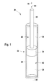
- a damper 26 which is preferably embodied as a shock absorber of a vehicle, comprises a damper cylinder 28 filled with a damper fluid 14, in which a piston unit 30 is movably arranged, which comprises a piston rod 32 and a piston ram 34, wherein the piston ram 34 is guided over the piston rod 32 in the damper cylinder 28.
- the piston ram 34 divides the damper cylinder 28 into an upper damper chamber 36 and into a lower damper chamber 38.
- the flow-through device 42 preferably forms a closed circuit.
- the flow-through device 42 comprises at least one rebound stage acting in a first flow direction 44 and / or at least one pressure stage acting in a second flow direction 46.
- a spring unit 10 is introduced into the through-flow device 42 of the vehicle damper 26 having at least one flow channel 16 and is used to set damper characteristic values.
- the flow channel 16 can be arranged for example in the piston ram 34, which is guided via the piston rod 32 in the damper cylinder 28 of the vehicle damper 26.
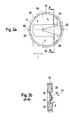
- the illustrated spring unit 10 has a spring element 12 with which the flow of the damper fluid 14 through the flow channel 16 can be regulated in order to set damper characteristic values.
- the flow channel 16 is introduced in the illustrated embodiment in a component or is laterally limited by several components that an axial support surface for the spring element 12 is provided.
- the spring element 12 has to bend a defined spring characteristic to the damper fluid 14 in the direction indicated by arrows Fig. 3 to let the indicated flow direction pass.
- the spring unit 10 In order to allow the flow of the damper fluid 14 through at least one flow channel 16 for setting damper characteristics in a simple manner, the spring unit 10 according to the invention an adjusting means 20 for adjusting the spring characteristic of the spring element 12, which is designed as an elastic spring washer, which is a substantially vertical to a bending line 24 of the spring washer 12 extending, comprising a height h having bead 22, wherein the adjustment means 20 for adjusting the spring characteristic of the spring washer 12, the height h of the bead 22 changed.
- the adjusting device 20 the spring stiffness of the at least one spring washer 12 a.
- the adjusting device 20 is provided to change by elastic deformation of the spring washer 12 whose spring stiffness.
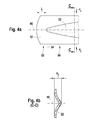
- the adjusting device 20 influences the elastic properties of the spring washer 12 by the adjustment 20, the effective length I, the so-called bending beam length of the spring washer 12, and the bending resistance torque W of the spring washer 12 changed.
- the adjusting device 20 is designed as a force element in the form of a piezoelectric element and / or a Elektrohubmagnetiatas and / or a prestressed force storage element.
- the adjusting device 20 is preferably designed as a piezoelectric element, since 12 large forces must be generated at low distances to adjust the spring stiffness of the spring washer.
- the elastic spring washer 12 without being acted upon by the adjuster 20, so that the bead 22 has its original height h and the spring washer 12 has its original effective length I.
- the effective length I of the spring washer 12 is the length of the flat portion of the spring washer 12.
- the adjusting device 20 according to Fig. 2a and 2b arranged on opposite sides of the bead 22 on the spring washer 12 and the adjusting force F of the adjusting device 20 thus acts in the direction of the bending line 24 on the spring washer 12.
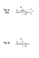
- the adjustment 20 according to Fig. 3a also be arranged above and below the bead 22 of the spring washer 12 and the adjusting force F of the adjusting device 20 thus acts in the direction of a vertical axis 40 on the spring washer 12.
- the adjusting device 20 is designed and / or arranged on the spring washer 12 that they both compressive forces as well as tensile forces can apply to the spring washer 12.
- the elastic spring washer 12 has a substantially perpendicular to a bending line 24 of the spring washer 12 in the direction of a longitudinal axis 56 extending, a height h having bead 22.
- a bead 22 is provided, the height h and their Width b decrease in the course of the longitudinal axis 56 until the bead 22 merges into a flat surface of the spring washer 12 or expires towards zero.
- the bead 22 is introduced into the spring washer 12, preferably by embossing, during the production of the spring washer 12.
- the spring washer 12 preferably comprises at least one first section 52 and at least one second section 54, which is softer than the first section 52 and arranged in the region of the bead 22 is to facilitate the formation of the bead 22. Due to the formed bead 22, however, the spring washer 12 in the second section 54 receives a higher spring rigidity than the first section 52 in the direction of uplifting s.
- the Fig. 3a to 3d show the spring washer 12 with an acting on the spring washer 12, here the value zero adjusting force F, the effective length or free bending length I of the spring washer 12 and the direction of deflection s of the spring washer 12 at a control edge 60 of the flow channel 16.
- the adjuster 20 changes the height h of the bead 22, wherein an increase in the height h of the bead 22 to increase the spring stiffness of the spring washer 12 and a reduction in the height h of the bead 22 to a Reduction of the spring stiffness of the spring washer 12 leads.
- the spring washer 12 has a lower spring stiffness and is thus flexurally soft.
- deviating shaped, beaded spring elements are possible to adjust the damper characteristics, such as corrugated or scored spring elements.
Landscapes
- Engineering & Computer Science (AREA)
- General Engineering & Computer Science (AREA)
- Mechanical Engineering (AREA)
- Physics & Mathematics (AREA)
- Electromagnetism (AREA)
- Fluid-Damping Devices (AREA)
Applications Claiming Priority (1)
| Application Number | Priority Date | Filing Date | Title |
|---|---|---|---|
| DE200910001811 DE102009001811A1 (de) | 2009-03-24 | 2009-03-24 | Federeinheit für einen Dämpfer und zugehöriger Dämpfer |
Publications (1)
| Publication Number | Publication Date |
|---|---|
| EP2233773A2 true EP2233773A2 (fr) | 2010-09-29 |
Family
ID=42244998
Family Applications (1)
| Application Number | Title | Priority Date | Filing Date |
|---|---|---|---|
| EP20100151534 Withdrawn EP2233773A2 (fr) | 2009-03-24 | 2010-01-25 | Unité de ressort pour un amortisseur et amortisseur correspondant |
Country Status (2)
| Country | Link |
|---|---|
| EP (1) | EP2233773A2 (fr) |
| DE (1) | DE102009001811A1 (fr) |
Citations (1)
| Publication number | Priority date | Publication date | Assignee | Title |
|---|---|---|---|---|
| DE102006037172A1 (de) | 2006-08-09 | 2008-02-14 | Robert Bosch Gmbh | Dämpfer |
-
2009
- 2009-03-24 DE DE200910001811 patent/DE102009001811A1/de not_active Withdrawn
-
2010
- 2010-01-25 EP EP20100151534 patent/EP2233773A2/fr not_active Withdrawn
Patent Citations (1)
| Publication number | Priority date | Publication date | Assignee | Title |
|---|---|---|---|---|
| DE102006037172A1 (de) | 2006-08-09 | 2008-02-14 | Robert Bosch Gmbh | Dämpfer |
Also Published As
| Publication number | Publication date |
|---|---|
| DE102009001811A1 (de) | 2010-09-30 |
Similar Documents
| Publication | Publication Date | Title |
|---|---|---|
| EP0300204B1 (fr) | Amortisseur | |
| DE102010026569B4 (de) | Regelungseinrichtung zur Reduzierung einer Schwingungsbewegung einer federkraftbeaufschlagten schwingenden Vorrichtung | |
| EP0400395B1 (fr) | Amortisseur de choc | |
| DE102012014583B4 (de) | Ventilstruktur eines Schwingungsdämpfers | |
| EP3463998B1 (fr) | Dispositif de simulation de force de pédale | |
| EP0367949B1 (fr) | Système de suspension pour véhicules | |
| DE102017115347B4 (de) | Fahrzeugsitz mit einstellbarem Dämpfer und Nutzfahrzeug | |
| DE102005046276B3 (de) | Dämpfventileinrichtung mit progressivem Dämpfkraftverlauf | |
| DE3932669A1 (de) | Hydraulischer stossdaempfer mit linearer daempfungscharakteristik | |
| DE102008058394A1 (de) | Schwingungsdämpfer zur Steuerung von Dämpfungskraftcharakteristiken | |
| DE102015211891A1 (de) | Frequenzabhängige Dämpfventilanordnung | |
| EP3417177B1 (fr) | Actionneur hydraulique, bras de robot, main de robot et procédé de fonctionnement | |
| EP0565832B1 (fr) | Amortisseur de vibrations hydraulique pour véhicule | |
| WO2014206507A1 (fr) | Système d'amortissement à colonnes de liquide | |
| DE602005005009T2 (de) | Stoßdämpfer | |
| DE10258936A1 (de) | Federbein für eine Kraftfahrzeug-Radaufhängung | |
| EP3334953B1 (fr) | Dispositif pour coupler mécaniquement un corps monté amovible | |
| DE102004015065B4 (de) | Schwingungsdämpfer mit amplitudenabhängiger Dämpfkraft | |
| DE102017220273B4 (de) | Dämpfervorrichtung für ein Kraftfahrzeug sowie Kraftfahrzeug mit Dämpfervorrichtung | |
| EP2233773A2 (fr) | Unité de ressort pour un amortisseur et amortisseur correspondant | |
| DE3729187C2 (de) | Verstellbare Dämpfung | |
| DE102016217114B4 (de) | Frequenzabhängige Dämpfventilanordnung | |
| DE102012208684B4 (de) | Dämpferanordnung | |
| EP2233774A2 (fr) | Unité de ressort pour un amortisseur et amortisseur correspondant pour un véhicule | |
| DE102008042619A1 (de) | Federscheibe für einen Fahrzeugdämpfer und zugehöriger Fahrzeugdämpfer |
Legal Events
| Date | Code | Title | Description |
|---|---|---|---|
| PUAI | Public reference made under article 153(3) epc to a published international application that has entered the european phase |
Free format text: ORIGINAL CODE: 0009012 |
|
| AK | Designated contracting states |
Kind code of ref document: A2 Designated state(s): AT BE BG CH CY CZ DE DK EE ES FI FR GB GR HR HU IE IS IT LI LT LU LV MC MK MT NL NO PL PT RO SE SI SK SM TR |
|
| STAA | Information on the status of an ep patent application or granted ep patent |
Free format text: STATUS: THE APPLICATION IS DEEMED TO BE WITHDRAWN |
|
| 18D | Application deemed to be withdrawn |
Effective date: 20160802 |