EP2233774A2 - Unité de ressort pour un amortisseur et amortisseur correspondant pour un véhicule - Google Patents
Unité de ressort pour un amortisseur et amortisseur correspondant pour un véhicule Download PDFInfo
- Publication number
- EP2233774A2 EP2233774A2 EP20100151865 EP10151865A EP2233774A2 EP 2233774 A2 EP2233774 A2 EP 2233774A2 EP 20100151865 EP20100151865 EP 20100151865 EP 10151865 A EP10151865 A EP 10151865A EP 2233774 A2 EP2233774 A2 EP 2233774A2
- Authority
- EP
- European Patent Office
- Prior art keywords
- spring
- damper
- unit according
- washer
- flow
- Prior art date
- Legal status (The legal status is an assumption and is not a legal conclusion. Google has not performed a legal analysis and makes no representation as to the accuracy of the status listed.)
- Withdrawn
Links
- 239000012530 fluid Substances 0.000 claims abstract description 18
- 238000005452 bending Methods 0.000 claims abstract description 13
- 230000009467 reduction Effects 0.000 claims description 6
- 230000008859 change Effects 0.000 claims description 3
- 230000005489 elastic deformation Effects 0.000 claims description 3
- 230000007246 mechanism Effects 0.000 abstract description 3
- 238000004146 energy storage Methods 0.000 abstract description 2
- 230000000712 assembly Effects 0.000 description 5
- 238000000429 assembly Methods 0.000 description 5
- 230000000694 effects Effects 0.000 description 5
- 230000008901 benefit Effects 0.000 description 4
- 239000006096 absorbing agent Substances 0.000 description 3
- 230000035939 shock Effects 0.000 description 3
- 238000013016 damping Methods 0.000 description 2
- 230000007257 malfunction Effects 0.000 description 2
- 230000001105 regulatory effect Effects 0.000 description 2
- 238000005299 abrasion Methods 0.000 description 1
- 230000001133 acceleration Effects 0.000 description 1
- 230000009471 action Effects 0.000 description 1
- 230000005540 biological transmission Effects 0.000 description 1
- 238000006243 chemical reaction Methods 0.000 description 1
- 230000006835 compression Effects 0.000 description 1
- 238000007906 compression Methods 0.000 description 1
- 238000010276 construction Methods 0.000 description 1
- 238000011109 contamination Methods 0.000 description 1
- 230000001276 controlling effect Effects 0.000 description 1
- 230000001419 dependent effect Effects 0.000 description 1
- 238000006073 displacement reaction Methods 0.000 description 1
- 238000011156 evaluation Methods 0.000 description 1
- 238000004519 manufacturing process Methods 0.000 description 1
Images


Classifications
-
- F—MECHANICAL ENGINEERING; LIGHTING; HEATING; WEAPONS; BLASTING
- F16—ENGINEERING ELEMENTS AND UNITS; GENERAL MEASURES FOR PRODUCING AND MAINTAINING EFFECTIVE FUNCTIONING OF MACHINES OR INSTALLATIONS; THERMAL INSULATION IN GENERAL
- F16F—SPRINGS; SHOCK-ABSORBERS; MEANS FOR DAMPING VIBRATION
- F16F9/00—Springs, vibration-dampers, shock-absorbers, or similarly-constructed movement-dampers using a fluid or the equivalent as damping medium
- F16F9/32—Details
- F16F9/34—Special valve constructions; Shape or construction of throttling passages
- F16F9/348—Throttling passages in the form of annular discs or other plate-like elements which may or may not have a spring action, operating in opposite directions or singly, e.g. annular discs positioned on top of the valve or piston body
- F16F9/3485—Throttling passages in the form of annular discs or other plate-like elements which may or may not have a spring action, operating in opposite directions or singly, e.g. annular discs positioned on top of the valve or piston body characterised by features of supporting elements intended to guide or limit the movement of the annular discs
-
- F—MECHANICAL ENGINEERING; LIGHTING; HEATING; WEAPONS; BLASTING
- F16—ENGINEERING ELEMENTS AND UNITS; GENERAL MEASURES FOR PRODUCING AND MAINTAINING EFFECTIVE FUNCTIONING OF MACHINES OR INSTALLATIONS; THERMAL INSULATION IN GENERAL
- F16F—SPRINGS; SHOCK-ABSORBERS; MEANS FOR DAMPING VIBRATION
- F16F9/00—Springs, vibration-dampers, shock-absorbers, or similarly-constructed movement-dampers using a fluid or the equivalent as damping medium
- F16F9/32—Details
- F16F9/44—Means on or in the damper for manual or non-automatic adjustment; such means combined with temperature correction
- F16F9/46—Means on or in the damper for manual or non-automatic adjustment; such means combined with temperature correction allowing control from a distance, i.e. location of means for control input being remote from site of valves, e.g. on damper external wall
- F16F9/461—Means on or in the damper for manual or non-automatic adjustment; such means combined with temperature correction allowing control from a distance, i.e. location of means for control input being remote from site of valves, e.g. on damper external wall characterised by actuation means
-
- F—MECHANICAL ENGINEERING; LIGHTING; HEATING; WEAPONS; BLASTING
- F16—ENGINEERING ELEMENTS AND UNITS; GENERAL MEASURES FOR PRODUCING AND MAINTAINING EFFECTIVE FUNCTIONING OF MACHINES OR INSTALLATIONS; THERMAL INSULATION IN GENERAL
- F16F—SPRINGS; SHOCK-ABSORBERS; MEANS FOR DAMPING VIBRATION
- F16F9/00—Springs, vibration-dampers, shock-absorbers, or similarly-constructed movement-dampers using a fluid or the equivalent as damping medium
- F16F9/32—Details
- F16F9/44—Means on or in the damper for manual or non-automatic adjustment; such means combined with temperature correction
- F16F9/46—Means on or in the damper for manual or non-automatic adjustment; such means combined with temperature correction allowing control from a distance, i.e. location of means for control input being remote from site of valves, e.g. on damper external wall
- F16F9/464—Control of valve bias or pre-stress, e.g. electromagnetically
-
- F—MECHANICAL ENGINEERING; LIGHTING; HEATING; WEAPONS; BLASTING
- F16—ENGINEERING ELEMENTS AND UNITS; GENERAL MEASURES FOR PRODUCING AND MAINTAINING EFFECTIVE FUNCTIONING OF MACHINES OR INSTALLATIONS; THERMAL INSULATION IN GENERAL
- F16F—SPRINGS; SHOCK-ABSORBERS; MEANS FOR DAMPING VIBRATION
- F16F2224/00—Materials; Material properties
- F16F2224/02—Materials; Material properties solids
- F16F2224/0283—Materials; Material properties solids piezoelectric; electro- or magnetostrictive
Definitions
- the invention relates to a spring unit for a damper according to the preamble of independent claim 1 and a corresponding damper for a vehicle comprising at least one such spring unit.
- Passive shock absorber pistons are known from the prior art, in which spring units are generally used with spring elements designed as spring packs, which consist of a plurality of spring washers for generating a specific damping force characteristic.
- the spring stiffness of the spring package in these conventional shock absorber pistons is tuned once during development and can then no longer be adjusted. This principle allows a cost-effective and robust construction of a damper piston with at the same time very good and proven in practice curves of the damper characteristics.
- a damper for a vehicle comprises a damper cylinder, in which a piston ram is guided via a piston rod.
- the flow rate of a damper fluid is adjustable.
- control means are arranged within the damper cylinder having two independent control circuits for a Werner-Field® 845° F.
- the control means the flow of the damper fluid during the compression stage period in a first flow direction with first adjustment means and during the Switzerlandnicinperiode in a second flow direction with second adjustment means regulate.
- the adjusting means comprise sliding on spring assemblies sliding units, which by moving on Modify the spring assemblies the bending beam length of the spring assemblies and thus the stiffness of the spring assemblies the spring assemblies.
- the adjustment variables for the adjustment means can be determined, for example, by evaluating signals from sensor units.
- the sensor units are designed, for example, as pressure sensors, acceleration sensors and / or displacement sensors and include electronic circuits associated with the control and signal evaluation.
- the spring unit according to the invention for a damper, in particular a vehicle damper, with the features of independent claim 1 has the advantage that the spring unit has an adjusting device for adjusting the spring stiffness of the at least one spring element.
- the at least one spring element has to bend a defined Feder characterisitk to let pass the damper fluid in the direction of flow.
- An inventive damper for a vehicle comprises at least one spring unit according to the invention for controlling a damper fluid flow in at least one flow channel in order to set damper characteristics of the vehicle damper.
- the adjusting device adjusts the spring stiffness of the at least one spring element.
- the spring stiffness of the at least one spring element to simple The manner in which the opening behavior of the spring element is changed so that a flow of a damper fluid can be specifically controlled by at least one flow channel.
- the adjusting device is provided to change its spring stiffness by elastic deformation of the at least one spring element.
- the adjusting device influences the elastic properties of the spring element, in that the adjusting device changes the effective length of the spring element, the so-called bending beam length of the spring element.
- the adjusting device is designed as a piezo element and / or as an electro-lifting magnet element and / or as a prestressed force storage element.
- the adjusting device is designed as a piezo element and / or as an electro-lifting magnet element and / or as a prestressed force storage element.
- the at least one spring element is designed as an elastic spring washer.
- the simple in shape and manufacture spring washer can be produced inexpensively.
- the spring washer has a substantially central, a diameter-containing recess in which the adjusting device is arranged.
- the adjusting device for adjusting the spring stiffness of the spring washer changes the diameter of the recess of the spring washer.
- an expansion of the diameter of the recess leads to an increase in the spring stiffness of the spring washer and a reduction in the expansion of the diameter of the recess to a reduction in the spring stiffness of the spring washer.
- the spring washer on a running around the recess, bent edge.
- a widening of the diameter leads to a further bending of the edge of the spring washer.
- large changes in the spring stiffness of the spring washer can be achieved via small changes in position of the bent-up edge.
- a damper 26 which is preferably embodied as a shock absorber of a vehicle, comprises a damper cylinder 28 filled with a damper fluid 14, in which a piston unit 30 is movably arranged, which comprises a piston rod 32 and a piston ram 34, wherein the piston ram 34 is guided over the piston rod 32 in the damper cylinder 28.
- the piston ram 34 divides the damper cylinder 28 into an upper damper chamber 36 and into a lower damper chamber 38.
- the damper fluid With an axial movement of the piston rod 32 and thus of the piston ram 34 relative to the damper cylinder 28, preferably in the direction of a vertical axis 40 of the damper 26, the damper fluid must be 14 flow through a arranged within the damper cylinder 28 flow device 42, which preferably has two flow channels 16, 18 which in Fig. 2 to 4 are shown.
- the flow-through device 42 preferably forms a closed circuit.
- the damper fluid flow 14 flows in the flow device 42 through the movement of the piston unit 30 directed in the direction of the vertical axis 40 of the damper 26 or the damper cylinder 28.
- the flow device 42 comprises at least one first flow direction 44 Rebound stage and / or at least one acting in a second flow direction 46 pressure stage.
- the adjusting means comprise at least one spring unit 10 ', 10 ".
- a spring unit 10 ', 10 "according to the invention in the two flow channels 16, 18 having flow device 42 of the vehicle damper 26 is introduced and is used for setting damper characteristics, wherein FIGS. 2 and 3 the spring unit 10 'in a first embodiment and Fig. 4
- the flow channels 16, 18 can be arranged, for example, in the piston ram 34, which is guided via the piston rod 32 in the damper cylinder 28 of the vehicle damper 26.
- the illustrated spring unit 10 ', 10 " has a spring element 12 ', 12 ", with which the flow of the damper fluid 14 through the flow channels 16, 18 can be regulated in order to set damper characteristics
- the flow channels 16, 18 are thus introduced into a component in the exemplary embodiment shown or are thus made of several components
- the spring element 12 ', 12 " has a defined spring characteristic for bending in order to allow the damper fluid 14 to pass in the direction of flow indicated by arrows.
- the spring unit 10 ', 10 according to the invention an adjusting means 20', 20" for adjusting the spring characteristic of the spring element 12 ', 12 "
- the adjusting device 20 ', 20 sets the spring rigidity of the at least one spring element 12', 12".
- the adjusting device 20 ', 20 is provided to change by elastic deformation of the spring element 12', 12" whose spring stiffness.
- the adjusting device 20 ', 20 affects the elastic properties of the spring element 12' and 12" by the adjuster 20 ', 20 “changes the effective length, the so-called bending beam length of the spring element 12', 12".
- the adjusting device 20 ', 20 is preferably designed as a force element in the form of a piezoelectric element and / or an electro-lifting magnet element and / or a prestressed energy storage element the spring stiffness of the spring element 12 ', 12 "large forces must be generated at low distances.
- the spring disk 12 ', 12 has a substantially central, a diameter d-containing recess 22', 22", in which the preferably designed as a piezoelectric adjusting device 20 ', 20 "is arranged.
- the spring disk 12 ', 12 has a bent edge 24', 24" running around the cutout 22 ', 22 ", which can be realized in a simple manner, widening the diameter d of the cutout 22', 22" a further bending of the edge 24 ', 24 "of the spring washer 12', 12", so that the effective length I of the spring washer 12 'and 12 ", the so-called bending beam length of the spring washer 12', 12" is shortened, whereby the spring stiffness of In the present embodiments, the effective length I of the spring washer 12 ', 12 "is the length of the flat portion of the spring washer 12', 12".
- Fig. 2 shows the spring unit 10 'with the elastic spring washer 12' and an unconfirmed adjuster 20 ', so that the diameter d of the recess 22' of the spring washer 12 'its original size d 1 and the spring washer 12' has an effective length I 1 .
- the spring washer 12 ' has a lower spring stiffness and is thus flexurally soft.
- Fig. 3 shows the spring unit 10 'with the elastic spring washer 12' and the actuated adjuster 20 '. By electrically initiated expansion of the adjustment device 20 'designed as a piezoelectric element, its circumference becomes larger and the original diameter d 1 of the spring washer 12' is widened to the diameter d 2 .
- the bent-up edge 24 'of the spring washer 12' is further bent or steeper erect, so that the effective length I of the spring washer 12 ', the so-called bending beam length of the spring washer 12' is shortened to the length I 2 , whereby the spring stiffness of the spring washer 12 'is increased.
- the actuation of the adjusting device 20 'thus leads to a stiffness-increasing effect.
- the spring disk 12 "of the spring unit 10 unlike the first embodiment, has an abutment 48 "on the bent edge 24" running around the recess 22 ", which abuts against a lateral surface 50" of the adjusting device 20 " Conversion of the spring washer 12 ", the action of the adjuster 20” can be changed so that the operation of the adjuster 20 "leads to a stiffness-reducing effect.
- the flow of damper fluid 14 may be analogous to the first embodiment by influencing the elastic properties of the spring washer 12 "are regulated.
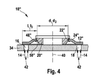
- Fig. 4 shows the unactuated adjusting device 20 ", wherein the recess 22" of the spring washer 12 "has the diameter d 3.
- the bent-up edge 24 is in a steep position, so that the effective length I of the spring washer 12", the so-called bending beam length of the spring washer 12 "is shortened to the length I 3 , whereby the spring stiffness of the spring washer 12" is increased.
- the adjusting device 20 designed as a piezoelectric element, which is not shown here, its circumference increases and presses the steeply uplifted edge 24" of the spring washer 12 “downwards, as the projection 48" slides along the lateral surface 50 "of the adjusting device 20” slides down.
- the effective length I of the spring washer 12 " As a result, the effective length I of the spring washer 12 ", the so-called bending beam length of the spring washer 12” is extended and the diameter d 3 is increased, whereby the spring stiffness of the spring washer 12 "is lowered and the spring washer 12" is flexible.
- the actuation of the adjusting device 20" thus leads to a stiffness-reducing effect , In the case of a malfunction, this offers advantages with regard to a stiff and safety-relevant damper characteristic. In an undesirable failure of the adjustment of the erected edge of the spring element remains in its rigid position, whereby the spring stiffness of the spring element increases and the reliability is maintained.
- damper characteristics such as, for example, corrugated or scored spring elements and / or radially acting adjusting devices.
Landscapes
- Engineering & Computer Science (AREA)
- General Engineering & Computer Science (AREA)
- Mechanical Engineering (AREA)
- Physics & Mathematics (AREA)
- Electromagnetism (AREA)
- Fluid-Damping Devices (AREA)
- Vehicle Body Suspensions (AREA)
Applications Claiming Priority (1)
| Application Number | Priority Date | Filing Date | Title |
|---|---|---|---|
| DE200910001816 DE102009001816A1 (de) | 2009-03-24 | 2009-03-24 | Federeinheit für einen Dämpfer und zugehöriger Dämpfer für ein Fahrzeug |
Publications (1)
| Publication Number | Publication Date |
|---|---|
| EP2233774A2 true EP2233774A2 (fr) | 2010-09-29 |
Family
ID=42244920
Family Applications (1)
| Application Number | Title | Priority Date | Filing Date |
|---|---|---|---|
| EP20100151865 Withdrawn EP2233774A2 (fr) | 2009-03-24 | 2010-01-28 | Unité de ressort pour un amortisseur et amortisseur correspondant pour un véhicule |
Country Status (2)
| Country | Link |
|---|---|
| EP (1) | EP2233774A2 (fr) |
| DE (1) | DE102009001816A1 (fr) |
Citations (1)
| Publication number | Priority date | Publication date | Assignee | Title |
|---|---|---|---|---|
| DE102006037172A1 (de) | 2006-08-09 | 2008-02-14 | Robert Bosch Gmbh | Dämpfer |
-
2009
- 2009-03-24 DE DE200910001816 patent/DE102009001816A1/de not_active Withdrawn
-
2010
- 2010-01-28 EP EP20100151865 patent/EP2233774A2/fr not_active Withdrawn
Patent Citations (1)
| Publication number | Priority date | Publication date | Assignee | Title |
|---|---|---|---|---|
| DE102006037172A1 (de) | 2006-08-09 | 2008-02-14 | Robert Bosch Gmbh | Dämpfer |
Also Published As
| Publication number | Publication date |
|---|---|
| DE102009001816A1 (de) | 2010-09-30 |
Similar Documents
| Publication | Publication Date | Title |
|---|---|---|
| EP0400395B1 (fr) | Amortisseur de choc | |
| EP3463998B1 (fr) | Dispositif de simulation de force de pédale | |
| EP1538367B1 (fr) | Assemblage d'un clapet amortisseur à caractéristique progressive | |
| DE102005046276B3 (de) | Dämpfventileinrichtung mit progressivem Dämpfkraftverlauf | |
| DE102013107728A1 (de) | Klemmvorrichtung für eine längsverstellbare und/oder höhenverstellbare Lenksäule eines Fahrzeugs | |
| EP2017421A1 (fr) | Dispositif amortisseur pour éléments de meubles | |
| EP0300204A2 (fr) | Amortisseur | |
| EP2501967B1 (fr) | Soupape de commande avec un organe mobile dans le corps de soupape | |
| DE102015211891A1 (de) | Frequenzabhängige Dämpfventilanordnung | |
| EP0565832B1 (fr) | Amortisseur de vibrations hydraulique pour véhicule | |
| DE102019117233A1 (de) | Druckrückführkolben mit Ringschulter | |
| DE102014210702A1 (de) | Frequenzabhängige Dämpfventilanordnung | |
| EP1644567B1 (fr) | Amortisseur a friction notamment destine a des lave-linge a tambour | |
| DE102004050732A1 (de) | Dämpfventileinrichtung mit progressiver Dämpfkraftkennlinie | |
| EP2327903A2 (fr) | Dispositif de robinet de vapeur doté d'une ligne de référence de force motrice de la vapeur à plusieurs étapes | |
| EP2404078B1 (fr) | Système d'amortissement pour amortissement de butée | |
| DE10161801A1 (de) | Kolbenbefestigung | |
| DE102017220273B4 (de) | Dämpfervorrichtung für ein Kraftfahrzeug sowie Kraftfahrzeug mit Dämpfervorrichtung | |
| DE102016217114B4 (de) | Frequenzabhängige Dämpfventilanordnung | |
| EP2233774A2 (fr) | Unité de ressort pour un amortisseur et amortisseur correspondant pour un véhicule | |
| DE102012208684B4 (de) | Dämpferanordnung | |
| DE102019202431B3 (de) | Frequenzabhängige Dämpfventileinrichtung | |
| DE19846543C2 (de) | Aktuator, insbesondere für ein elektromagnetisch verstellbares Ventil | |
| EP2233773A2 (fr) | Unité de ressort pour un amortisseur et amortisseur correspondant | |
| EP2430328B1 (fr) | Unité ressort pour un amortisseur et amortisseur associé |
Legal Events
| Date | Code | Title | Description |
|---|---|---|---|
| PUAI | Public reference made under article 153(3) epc to a published international application that has entered the european phase |
Free format text: ORIGINAL CODE: 0009012 |
|
| AK | Designated contracting states |
Kind code of ref document: A2 Designated state(s): AT BE BG CH CY CZ DE DK EE ES FI FR GB GR HR HU IE IS IT LI LT LU LV MC MK MT NL NO PL PT RO SE SI SK SM TR |
|
| AX | Request for extension of the european patent |
Extension state: AL BA RS |
|
| STAA | Information on the status of an ep patent application or granted ep patent |
Free format text: STATUS: THE APPLICATION IS DEEMED TO BE WITHDRAWN |
|
| 18D | Application deemed to be withdrawn |
Effective date: 20140801 |