EP2233992B1 - Dispositif de commande pour une machine électrique portable dotée d'un bus de communication et machine - Google Patents
Dispositif de commande pour une machine électrique portable dotée d'un bus de communication et machine Download PDFInfo
- Publication number
- EP2233992B1 EP2233992B1 EP10001826.6A EP10001826A EP2233992B1 EP 2233992 B1 EP2233992 B1 EP 2233992B1 EP 10001826 A EP10001826 A EP 10001826A EP 2233992 B1 EP2233992 B1 EP 2233992B1
- Authority
- EP
- European Patent Office
- Prior art keywords
- bus
- potential
- section
- electrical machine
- portable electrical
- Prior art date
- Legal status (The legal status is an assumption and is not a legal conclusion. Google has not performed a legal analysis and makes no representation as to the accuracy of the status listed.)
- Active
Links
Images
Classifications
-
- G—PHYSICS
- G05—CONTROLLING; REGULATING
- G05B—CONTROL OR REGULATING SYSTEMS IN GENERAL; FUNCTIONAL ELEMENTS OF SUCH SYSTEMS; MONITORING OR TESTING ARRANGEMENTS FOR SUCH SYSTEMS OR ELEMENTS
- G05B19/00—Program-control systems
- G05B19/02—Program-control systems electric
- G05B19/04—Program control other than numerical control, i.e. in sequence controllers or logic controllers
- G05B19/042—Program control other than numerical control, i.e. in sequence controllers or logic controllers using digital processors
-
- A—HUMAN NECESSITIES
- A47—FURNITURE; DOMESTIC ARTICLES OR APPLIANCES; COFFEE MILLS; SPICE MILLS; SUCTION CLEANERS IN GENERAL
- A47L—DOMESTIC WASHING OR CLEANING; SUCTION CLEANERS IN GENERAL
- A47L11/00—Machines for cleaning floors, carpets, furniture, walls, or wall coverings
- A47L11/40—Parts or details of machines not provided for in groups A47L11/02 - A47L11/38, or not restricted to one of these groups, e.g. handles, arrangements of switches, skirts, buffers, levers
-
- A—HUMAN NECESSITIES
- A47—FURNITURE; DOMESTIC ARTICLES OR APPLIANCES; COFFEE MILLS; SPICE MILLS; SUCTION CLEANERS IN GENERAL
- A47L—DOMESTIC WASHING OR CLEANING; SUCTION CLEANERS IN GENERAL
- A47L9/00—Details or accessories of suction cleaners, e.g. mechanical means for controlling the suction or for effecting pulsating action; Storing devices specially adapted to suction cleaners or parts thereof; Carrying-vehicles specially adapted for suction cleaners
- A47L9/28—Installation of the electric equipment, e.g. adaptation or attachment to the suction cleaner; Controlling suction cleaners by electric means
- A47L9/2805—Parameters or conditions being sensed
-
- A—HUMAN NECESSITIES
- A47—FURNITURE; DOMESTIC ARTICLES OR APPLIANCES; COFFEE MILLS; SPICE MILLS; SUCTION CLEANERS IN GENERAL
- A47L—DOMESTIC WASHING OR CLEANING; SUCTION CLEANERS IN GENERAL
- A47L9/00—Details or accessories of suction cleaners, e.g. mechanical means for controlling the suction or for effecting pulsating action; Storing devices specially adapted to suction cleaners or parts thereof; Carrying-vehicles specially adapted for suction cleaners
- A47L9/28—Installation of the electric equipment, e.g. adaptation or attachment to the suction cleaner; Controlling suction cleaners by electric means
- A47L9/2805—Parameters or conditions being sensed
- A47L9/2821—Pressure, vacuum level or airflow
-
- A—HUMAN NECESSITIES
- A47—FURNITURE; DOMESTIC ARTICLES OR APPLIANCES; COFFEE MILLS; SPICE MILLS; SUCTION CLEANERS IN GENERAL
- A47L—DOMESTIC WASHING OR CLEANING; SUCTION CLEANERS IN GENERAL
- A47L9/00—Details or accessories of suction cleaners, e.g. mechanical means for controlling the suction or for effecting pulsating action; Storing devices specially adapted to suction cleaners or parts thereof; Carrying-vehicles specially adapted for suction cleaners
- A47L9/28—Installation of the electric equipment, e.g. adaptation or attachment to the suction cleaner; Controlling suction cleaners by electric means
- A47L9/2836—Installation of the electric equipment, e.g. adaptation or attachment to the suction cleaner; Controlling suction cleaners by electric means characterised by the parts which are controlled
- A47L9/2842—Suction motors or blowers
-
- A—HUMAN NECESSITIES
- A47—FURNITURE; DOMESTIC ARTICLES OR APPLIANCES; COFFEE MILLS; SPICE MILLS; SUCTION CLEANERS IN GENERAL
- A47L—DOMESTIC WASHING OR CLEANING; SUCTION CLEANERS IN GENERAL
- A47L9/00—Details or accessories of suction cleaners, e.g. mechanical means for controlling the suction or for effecting pulsating action; Storing devices specially adapted to suction cleaners or parts thereof; Carrying-vehicles specially adapted for suction cleaners
- A47L9/28—Installation of the electric equipment, e.g. adaptation or attachment to the suction cleaner; Controlling suction cleaners by electric means
- A47L9/2857—User input or output elements for control, e.g. buttons, switches or displays
-
- A—HUMAN NECESSITIES
- A47—FURNITURE; DOMESTIC ARTICLES OR APPLIANCES; COFFEE MILLS; SPICE MILLS; SUCTION CLEANERS IN GENERAL
- A47L—DOMESTIC WASHING OR CLEANING; SUCTION CLEANERS IN GENERAL
- A47L9/00—Details or accessories of suction cleaners, e.g. mechanical means for controlling the suction or for effecting pulsating action; Storing devices specially adapted to suction cleaners or parts thereof; Carrying-vehicles specially adapted for suction cleaners
- A47L9/28—Installation of the electric equipment, e.g. adaptation or attachment to the suction cleaner; Controlling suction cleaners by electric means
- A47L9/2894—Details related to signal transmission in suction cleaners
-
- H—ELECTRICITY
- H04—ELECTRIC COMMUNICATION TECHNIQUE
- H04L—TRANSMISSION OF DIGITAL INFORMATION, e.g. TELEGRAPHIC COMMUNICATION
- H04L12/00—Data switching networks
- H04L12/28—Data switching networks characterised by path configuration, e.g. LAN [Local Area Networks] or WAN [Wide Area Networks]
- H04L12/40—Bus networks
- H04L12/40006—Architecture of a communication node
- H04L12/40013—Details regarding a bus controller
Definitions
- the invention relates to a portable electric machine, in the form of a hand-held machine tool or a suction device, with a control device for controlling at least one component of the machine, in particular an electric motor, according to the preamble of claim 1.
- a two-wire field device for process automation technology for connecting at least one sensor element with a galvanic isolation circuit is off DE 10 2006 060 447 A1 known.
- a basic idea of the invention is to handle the communication between the first and the second potential range-it could also be a third or further potential range-via a data bus, suitable for electrical isolation between the respective potential ranges Transmission means are provided, for example, optocouplers, magnetic transformers or the like. Thus, a potential separation is realized. Via the data bus, a large amount of information can be transmitted between the different potential areas. The number of required data lines is thereby reduced.
- a preferred embodiment of the invention provides that the primary bus section and / or the secondary bus section are designed as a single-wire bus.
- a further bus section is expedient, which is likewise connected via galvanically separating transmission means to the first or second potential region or the primary bus section or the secondary bus section.
- the single-wire bus is expediently designed for bidirectional transmission. In principle, however, it is also possible that only transmission or reception is effected on the respective primary bus section or secondary bus section or a sub-branch thereof. Thus, therefore, on sections of the data bus also unidirectional transfers to be realized on corresponding sub-branches.
- the single-wire bus has the advantage that the number of required lines is minimized. Only a single bus line is required whose potential deviates from a second potential, for example ground or a supply potential.
- the transmission means expediently have a separate transmission device for each transmission direction, for example two separate optical couplers, two separate magnetic transmitters or the like.
- the first transmission device is preferably connected to an output and the second transmission device is connected to a separate input from the output of the first communication device to avoid feedback. It goes without saying that other measures, for example a transistor network, decoupling via operational amplifiers or the like, may be provided to avoid feedback.
- the first transmission device and the second transmission device are expediently connected to one another on the secondary bus section.
- a bidirectional transmission is realized on the part of the at least one second communication device.
- the inventive concept provides that also further communication devices can be connected to the data bus.
- These communication devices may be part of, for example, the portable electric machine or external, separate from the portable electric machine Communication devices, such as displays, diagnostic equipment, computers or the like.
- the third communication device is thus detachably connectable to the primary bus section or the secondary bus section.
- the third or further communication device can be connected to that bus section which allows a bidirectional transmission on one and the same bus line.
- this secondary bus section is advantageous for connecting further communication devices.
- first and / or the at least one second communication device could in principle be formed by bus communication modules that can be controlled, for example, by a microprocessor.
- the first and / or the second communication device are formed directly by a microprocessor.
- the microprocessor is, for example, able to control the at least one component of the machine, for example an electric motor, and at the same time to cope directly with the communication via the data bus.
- the sensor can also be configured to process at least one sensor signal. It is understood that a division of labor is expedient, for example, that a microprocessor assigned to the first potential range is provided for controlling the electrical component, while a second microprocessor, which is assigned to the second potential range, processes sensor signals.
- the data bus for example the primary bus section or the secondary bus section, is expediently bidirectional connected to send and receive connection provided by the microprocessor.
- the primary bus section and / or the secondary bus section are expediently designed as open-collector buses. So here is a simple bus architecture realized, which is inexpensive.
- the first potential region and the second potential region are preferably arranged on a single printed circuit board. It is expedient if the first communication device, the second communication device and / or the transmission means are arranged on the same, single circuit board. It is understood that, for example, the transmission means could also be implemented as a separate component.
- the printed circuit board expediently forms part of a printed circuit board module in which a guide body arrangement with at least one guide body separate from the printed circuit board is arranged on a flat side.
- This guide body serves, for example, for transmitting a network potential which is also present on the printed circuit board on the first or second potential region.
- the guide body is arranged, for example, on a flat side which is opposite to a flat side on which electrical components, for example the communication devices and / or the transmission means, are arranged.
- the guide body expediently has at least one printed circuit board contact projection, which penetrates the printed circuit board at a contact opening or penetrates into the printed circuit board. This contact projection protrudes in front of a guide body connecting portion which runs along the flat side of the printed circuit board.
- an intermediate body is expediently arranged, which is preferably plate-shaped. Also, on a side facing away from the circuit board side of the guide body, it is advantageous if another body, such as a bottom body, is arranged. This further body / bottom body is preferably plate-shaped or trough-like.
- the first potential range is associated, for example, with a network potential of an AC voltage network
- the second potential range is associated with a potential that is lower than the network body potential, for example a touch potential that can be safely touched by a user.
- the communication devices are expediently designed for a competing communication on the data bus. For this purpose, it is advantageous if the communication device has a wait phase "wait" after a start signal announcing a bus message, within which a respective other communication device can start to send a bus message. This avoids collisions.
- the waiting phase is preferably associated with a reception level. Thus, therefore, the communication devices are switched to receive during the waiting phase, so that a second communication device can start with the desired communication from her.
- the length of a waiting phase of a communication device expediently depends on its transmission priority. Thus, it is possible for a higher priority communication device to start transmitting while a lower priority communication device is waiting for a transmission opportunity.
- the communication devices on the data bus by means of a clock integrally containing transmit encoding, such as a Manchester encoding send.
- a kind of digital phase modulation is realized.
- the DC components are minimized, so that, for example, the use of transformers on the data bus is possible.
- the communication devices communicate on the data bus expediently bus messages of variable length, so that an adaptation to the respective transmission requirements is readily possible.
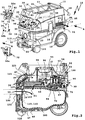
- a suction motor 12 for generating a suction flow 13 is arranged, which is sucked into the sucker housing 11 via a suction inlet 14.
- a hose not shown, can be connected.
- a filter arrangement 15 for separating particles from the suction flow 13.
- a receptacle 17 for receiving the suction hose and / or a connection cable 18, with which the suction device 10 is connected to an electrical supply network with eg 110 volts or 230 volts AC.
- an electrical supply network with eg 110 volts or 230 volts AC.
- a suction device with an accumulator would be possible.
- the suction device 10 is a portable suction device, on the underside driving rollers 19, 20 are arranged.
- the front casters 20 are castors. Furthermore, the suction device 10 can be grasped on a carrying handle 21 on the upper side 16.
- a control wall 23 with controls 24 for operating the suction device 10.
- the control wall 23 is suitably inclined, so that the controls 24 are easy to operate from diagonally above.
- the controls 24 include a switch 25, which forms a main switch, so to speak. With the switch 25, the suction motor 12 can be switched on and off. Further, an automatic mode is adjustable, in which the suction motor 12 always runs when a connected load receives electrical power through the suction device 10, which will be explained later. With the help of a Saugados- or speed switch 26, a power of the suction motor 12 can be adjusted.
- An adaptation switch 27 allows electrical adaptation of the suction device 10 to a respective suction inlet 14 connected suction hose. With a cleaning switch 28, a cleaning function of the suction device 10 can be switched on and / or parameterized.
- An outlet 29 which is firmly installed on the suction device 10 makes it possible to plug in an electrical energy consumer.
- the socket 29 is electrically connected to the connecting cable 18.
- a collecting housing part 31, of the sucker housing 11, an interior space 47 or collecting space 110 for collecting separated from the suction flow 13 particles and / or segregated moisture is provided in which optionally a large-size filter bag 48 of the filter assembly 15 can be arranged.
- a suction inlet 56 leading to the suction motor 12 is preceded by a main filter 61.
- the suction flow 13 is sucked into the filter bag 48 through the suction inlet 14, to which a suction hose 190 can be arranged.
- the filter bag 48 receives in the suction flow 13 contained particles 180.
- the suction flow 13 is generated by the suction motor 12, which sucks the suction flow 13 through the main filter 61 through the suction inlet 56 therethrough.
- the suction inlet 56 is arranged downstream of the suction filter 10 on the upper side of the main filter 61.
- the suction inlet 56 is connected to a turbine inlet 70 of a suction turbine 71 of a motor module 58 containing the suction motor 12 via an air guide arrangement 55.
- the suction turbine 71 sucks the suction flow 13 through the turbine inlet 70 and blows it radially outward through mufflers 84, which may optionally have a filter function at the same time, and then through Saugstromauslässe 85 on the side walls of the sucker housing 11 to the outside of the sucker housing 11 addition.
- a cooling air flow 94 flows through a cooling air inlet 96 on the front wall 22 of the sucker housing 11.
- the cooling air stream 94 initially flows past a control device 97 of the suction device 10 and cools it.
- the cooling air flow 94 flows through the suction motor 12 and then flows out to the rear through a cooling air outlet 99 from the sucker housing 11, on which expediently a silencer 100 is provided.
- a grounding contact 137 is provided at a suction pipe connection 133, to which the suction hose 190 can be connected.
- the grounding contact 137 is configured as a spring contact, for example a spring tongue.
- the suction pipe connection 133, for example a pipe sleeve, and / or the suction hose 190 expediently consist of an electrically conductive material, in particular plastic, in particular in a contact area provided for the grounding contact 137.
- a sensor 121 detects a level of a liquid or other electrically conductive substance in the plenum 110 and generates a sensor signal in response thereto.
- the sensor 121 is preferably arranged on a printed circuit board 123 of the control device 97. From an outside of the sucker housing 11 electrically scannable (see FIG. 1 ) Detecting parts 119, 120 of the sensor 121 are in the collecting space 110, thus in the interior 47 of the collecting housing part 31, before. Signal connections between the detection parts 119, 120 outside the plenum 110, but electrically protected and hidden on the sucker housing 11th
- the control device 97 can be influenced by the operating elements 24.
- the circuit board 123 is disposed below the controls 24, i. below the control wall 23.
- the control device 97 is connected to the suction motor 12, in particular the motor module 58 via electrical lines, not shown, and controls this.
- On the operating wall 23 is a suitably designed in the manner of a receiving shaft, in FIG. 1 provided with a cover plate 38 module receptacle 30 for selectively receiving functional modules 50a-50c provided that provide electrical, optical and acoustic functions.
- the functional module 50a is eg a compressed air module for connecting a compressed air tool.
- the functional module 50a has a compressed air connection arrangement 51 with compressed air connections, to each of which a compressed air hose can be connected.
- a compressed air connection via the connection arrangement 51 by the function module 50a be looped through, wherein a compressed air path in the function module 50a via a compressed air sensor for detecting a compressed air flow leads.
- the compressed air sensor is electrically connected via module signal contacts 32 with suction device signal contacts 33 when the function module 50a is plugged into the module receptacle 30.
- the functional module 50b has a bus connection 34 with a bus contact 35 for connection to a data bus 36 of the suction device 10.
- a bus contact 35 of the suction device signal contacts 33 can be connected to the function module 50b.
- the functional module 50c has e.g. an electrical power supply terminal 73 for connection of an electrical load, such as an electric tool on.
- the power supply connection 73 comprises a socket 74, preferably a safety socket, which can be closed by means of a cover 75.
- Contacts 76, 77 and 78 of the socket 74 are connected via leads to contacts of a connector 82.
- the connector 82 is used to make electrical connections to supply contacts 83 inside the module receptacle 30 of the suction device 10, e.g. are provided for a protective conductor connection, a ground connection and a continuous current connection.
- sensor connections 223 are provided on the circuit board 123, for example post connectors.
- the sucker signal contacts 33 are electrically connected to circuit board signal contacts 224.
- Signal terminals 225 serve to connect further sensors, for example a temperature sensor for the suction motor 12, a flow or pressure sensor for the suction flow 13 or the like.
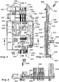
- the first microprocessor 212 is located on a first potential region 226 of the printed circuit board 123 and is networked with the components 211 located there, while the second microprocessor 213 is arranged in a second potential region 227 and connected to the local components 211, for example to the sensor connections 223 or the signal contact terminals 224, 225.
- the first potential region 226 is connected to a mains potential, which comes via the connection cable 18, while the second potential region 227 has a lower compared to the potential region 226 electric potential, for example in the amount of signal voltages of 5 to 12 volts or so.
- a potential separation between the two potential regions 226, 227 is realized by the optocouplers 214, 215 so that the operator does not come into contact with the higher electrical potential present in the potential region 226.
- the second potential region 227 is indicated in dashed lines.
- the remaining area of the printed circuit board 123 is assigned to the first potential area 226.
- a mains potential 230, a ground potential 231 and a protective conductor potential 232 which are connected via a connection line, not shown, come via the connection cable 18 and are connected via plug connector 233 to a plug connection arrangement 234 of the printed circuit board module 210.
- the plug connection arrangement 234 is electrically connected to further multipolar plug connection arrangements 235 for the electrical connection of the switch 25 of the main switch, for the electrical connection of the function module 50c and a plug connection arrangement 237 for connection to the socket 29.
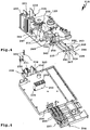
- guide bodies 238-242 of a guide body arrangement 243 are provided which extend along the lower flat side 219 of the printed circuit board 123.
- the guide bodies 238-242 have a flat shape. Its narrow sides 244 are facing the lower flat side 219.
- the printed circuit board 123 penetrating the printed circuit board contact projections 247, 248 and the Leit stresses plug connections 249, 250 are configured as plug-in projections which project in each case in front of the upper flat side 218 of the printed circuit board 123. There they are ready for contacting by a respective, in particular multi-pin connector, for example a multi-pin connector 251, which is plugged onto the plug connection arrangement 235.
- the connector 251 has in its interior a plurality of the connectors 233 corresponding connection sockets or plug connections 257, which are preferably arranged in a connector housing 252.
- the board contact protrusions 247, 248 are upstanding in front of the conductor connecting portions 253 the baffle 238-242 extending along the lower flat side 219 of the printed circuit board 123.
- connection sections 254, 255 of the guide bodies 238-242 on which the plug connections 249, 250 are provided.
- the plug-in connections 249, 250 protrude to the same side as the contact projections 247, 248, wherein it is quite possible that contact projections and / or plug-in connections in guide bodies used according to the invention protrude on different sides, in particular opposite sides.
- the guide body 238 is a plug-in connection 256 in the longitudinal direction forward, that is transverse to the Leit emotions plug-in connections 250.
- the plug connection 256 serves to connect a connector socket in the manner of the connector 233 to an electrical connection to the ground contact 137 on Suction pipe connection 133 produce.
- plug connection arrangements 234, 236, 237 All electrical contacts of the plug connection arrangements 234, 236, 237 are realized by contact projections of the guide body arrangement 243.
- plug-in connection arrangement 235 which is provided for the functional module 50c, there are also two further electrical plug-in connectors or electrical plug-in connections 257 which are exclusively in electrical connection with the printed circuit board 123.
- the plug housing 252 By optionally equipping receiving chambers of the plug housing 252 with sockets 258 and to each of these connected electrical lines, it is possible, for example, to realize different wiring variants without making any modifications to the printed circuit board module 210.
- the other plug connection arrangements 234, 236, 237 to the different connection lines as required, for example for different country variants or connectors can be connected.
- the two plug-in connections 257 which are connected exclusively to the printed circuit board 123, allow, for example, detection of a current flowing through the socket 74, so that the control device 97 the suction motor 12 with flowing current, that is at a connected to the suction device 10, running electrical Device, the suction motor 12 turns on.
- the socket 74 is designed switchable, so that, for example, only provides power when the switch 25 is switched to the operating position.
- the baffles 238-242 have conductor cross-sections which are larger than the conductor cross-sections of the tracks 220, so that they can conduct larger currents. This is particularly important with regard to the baffle 238 which conducts the protective conductor potential 232.
- the guide body 238 has no electrical contact with the printed circuit board 123 or the conductor tracks 220 or electrical components 211 disposed thereon.
- the guide body 238 penetrates the printed circuit board 123 only in the region of the plug connection arrangement 236 with a guide body contact projection 248. Below approximately in the region of a longitudinal center of the Circuit board 123 arranged plug connection arrangement 235, however, no electrical contact to the circuit board 123 and in particular not to the plug connection arrangement 235 is present. This is possible by the concept according to the invention.
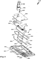
- a substantially plate-like intermediate body 260 is arranged, which expediently is electrically insulating.
- the intermediate body 260 consists for example of plastic material and extends at least in the region of the guide body arrangement 243 below the printed circuit board 123.
- a bottom body 261 is arranged, so to speak, as the base or base.
- the printed circuit board 123, the intermediate body 260, the guide body assembly 243 and finally the bottom body 261 form the essential components of the printed circuit board module 210. These components are expediently cast as a whole, which is advantageous both mechanically and in terms of electrical insulation.
- the printed circuit board 123, the intermediate body 260, and the below-mentioned baffle connecting portions 253 of the baffles 238-242 are received in a tub or a tub portion 262 of the bottom body 261.
- a peripheral wall 263 of the bottom body 261 extends.
- the trough region 262 is suitable for filling with a potting compound, which mechanically stabilizes and electrically insulates the printed circuit board module 210.
- a connection region 264 of the base or bottom body 261 is arranged next to the well region 262, which is integral with the well region 262 and accommodates the connection sections 255 of the guide bodies 238, 239 and 241.
- the guide body receptacles 265 are provided.
- the guide body 238, 239, 241 lie with their flat sides on inner walls of the guide body receptacles 265 substantially flat, so that they have a firm grip.
- the guide body receptacles 265 have plug receptacles 266 at their end regions remote from the well region 262, into the plug ends 267 of the guide bodies 239, 241, and / or the plug connection 256 is distrsteckbar.
- the plug connection 256 protrudes forward in front of an end wall of the printed circuit board module 210.
- the guide body receptacles 265 also extend into the well region 262.
- the guide body 238 associated with the guide body 238 extends away from the guide body receptacles 265 for the guide body 239-242 and is realized in the manner of a receiving groove.
- an optimal electrical isolation of the protective conductor potential 232 is realized.
- the guide body receptacles 265 for the guide bodies 239-242 have a common trough-like receiving area 268.
- the guide body connection portions of the guide bodies 239-242 extend parallel to each other, but are separated from one another by dividers 269.
- a plurality of separating webs 269 are provided, which each have a receiving slot or a receiving groove for the respective guide body 239-242.
- the retaining projections 270 fit in a complementary manner between the partitions 269 of the receiving region 268, which enables an optimum retention of the guide bodies 239-242 between the base body 261 and the intermediate body 260.
- the intermediate body 260 has openings or openings for the passage of the printed circuit board contact projections 247, 248.
- Error-free mounting of the guide bodies 238-242 on the printed circuit board module 210 is realized, for example, by a geometric configuration which may be individual to the guide bodies 238-242. This is a kind of mechanical coding that contributes to the error-free installation available. It should be noted that, for example, the guide body 240, 242 and 239, 241 each have the same shape, which reduces the variety of parts.
- mechanical codings 272 for example projections, are provided, which are provided for engagement in corresponding coding receptacles 273 on the printed circuit board 123.
- the geometric configuration of the guide body receptacles 265, 271 and the codings 272 and the Kodiernessn 273 thus allow a correct polarity and in particular error-free mounting of the guide 238-242 on PCB module 210.
- Board contact projections 247, 248 with little effort in the contact openings 245, 246 insert where they are received with little play.
- the contact openings 245, 246 have a substantially triangular shape.
- An inclined side 275 opposite projection 274 of the contact openings 245, 246 abuts a flat side of a respective printed circuit board contact projection 247, 248, while edge regions of the opposite flat side of the contact projections 247, 248 abut punctiform or line on the inclined sides 275.
- the plug-in connections 249 of the plug connection arrangement 234 are surrounded by insulation bodies 276, which together form a connector housing 277.
- the plug-in terminals 249 are housed by the insulating body 276, so that they are electrically insulated.
- the insulating body 276 or the connector housing 277 is integrally formed on the intermediate body 260 and project upwardly in front of a plate portion 278 of the intermediate body 260 before.
- the connector housing 277 also protrudes upward in front of the upper flat side 218 of the printed circuit board 123.
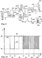
- the microprocessor 212 and the microprocessor 213 communicate with each other via the data bus 36. As a result, the number of required lines between the galvanically isolated potential regions 226, 227 is low.
- the first potential region 226 is assigned a primary bus section 281 of the data bus 36, while a secondary bus section 282 of the data bus 36 extends on the second potential region 227.
- the bus sections 281, 282 are coupled together by transmission means 280.
- the transmission means 280 realize a galvanic isolation.
- the two optocouplers 214, 215 form a first and a second transmission device 283, 284 for transmitting bus data from the primary bus section 281 to the secondary bus section 282 and vice versa.
- the optocouplers 214, 215 cause a galvanic separation of the data bus 36 in the two bus sections 281, 282. It is understood that instead of one or both optocouplers 214, 215 and a magnetic transformer is possible.
- the two microprocessors 212, 213 have different tasks.
- the first microprocessor 212 controls, for example, the power semiconductor or triac 216, for example via a control output 285.
- the microprocessor 212 has further inputs and outputs 286, for example for a speed monitoring the suction motor, a voltage synchronization, for controlling an acoustic signal means or the like. Further inputs and outputs are provided for direct connection to the primary bus section 281 of the data bus 36, namely a bus output 287 and a bus input 288.
- the data bus 36 is directly connected to the microprocessor 212 which directly handles the bus communication. An additional communication device is not necessary.
- the microprocessor 212 forms a first communication device 289.
- the second microprocessor 213 directly forms a communication device, namely a second communication device 290, which is connected to the secondary bus section 282 and thus to the data bus 36.
- the second microprocessor 213 has, in addition to inputs and outputs 291, which are provided, for example, for connecting the detection parts 119, 120, for connecting a temperature sensor, for connecting a sensor in one of the function modules 50a-50c or the like, a bus in / - output 292 which is connected to the secondary bus section 282.
- the bus input / output 292 is configured for bidirectional communication, that is, the microprocessor 213 receives and transmits data on a single bus input / output 292.
- the secondary bus portion 282 is configured as a one-wire bus having only a single bus 293 ,
- the bus line 293, which is intended for bidirectional communication, is connected via one or more pull-up resistors 294 to an upper potential level, for example 5 volts.
- a bus line 295 connected to the bus output 287 is connected via a pull-up resistor 297 and a bus line 296 connected to the bus input 288 via a resistor 299 via a pull-up resistor 298 connected to a ground potential.
- the bus line 295 is connected to a transmission input of the optocoupler 214, the bus line 296 provided with a data transmission for receiving the output of the optocoupler 215.
- the secondary bus section 282 On the side of the secondary bus section 282 this is not required.
- an amplifier circuit 300 with a transistor 301 At the input of the second communication device, that is the optocoupler 215, an amplifier circuit 300 with a transistor 301. It is understood that the amplifier circuit 300 is to be understood only as an example and can also be realized differently or can be dispensed with altogether, for example if a lower voltage is sufficient on the input side to the second communication device 290.
- the design of the secondary bus section 282 as a true single-wire bus, in which a single bus line 293 is sufficient, allows easy connection of other communication devices that can form part of the suction device 10, for example - or - in a preferred embodiment of the invention - can be configured as separate units.
- the bus contact 35 via a protective circuit 302 directly to the secondary bus section 282, thus connected to the data bus 36.
- the bus contact 35 therefore forms an interface 303 for connecting a communication device 304 separate from the machine 10, for example a diagnostic computer, a display device or the like.
- a functional module can be implemented, which is coupled directly to the data bus 36.
- Such a functional module which may be substantially similar in contour to the functional modules 50a-50c serves, for example, to output data communicated on the data bus 36, for example, sensor signals, fault messages, and the like.
- the communication devices 289, 290, 304 communicate with different priorities on the data bus 36.
- One exemplary communication is in FIG FIG. 10 shown.
- the second communication device 290 sends a bus message 305 on the data bus 36.
- the bus message 305 starts with a start pulse SI.
- the communication device 290 lowers a potential U on the data bus 36 from a high rest potential UH to a lower transmission potential UL.
- the data bus 36 is designed as an open-collector bus.
- the communication device 290 signals at the time t1 the desire to send a bus message.
- the start pulse ends and begins a waiting phase W1, within which the communication device 290 waits for transmission requests from other bus users of the data bus 36.
- the shorter waiting phase W2 compared to the waiting phase W1 signals that the bus message 306 has a higher priority than the bus message 305.
- the communication device 290 would omit further sending of the bus message 305 and give priority to the bus message 306.
- an address information AD begins, for example, the nature of the message and / or the sender of the message and / or the content of the message. This is followed at times t4 and t5 information pieces IN1, IN2, for example, contain four or eight bits of data.
- Bus messages on the data bus 36 may have variable lengths, that is, for example, that only the information part IN1 is transmitted or connect to the information part IN2 more, not shown information parts.
Landscapes
- Engineering & Computer Science (AREA)
- Mechanical Engineering (AREA)
- Computer Networks & Wireless Communication (AREA)
- Signal Processing (AREA)
- Physics & Mathematics (AREA)
- General Physics & Mathematics (AREA)
- Automation & Control Theory (AREA)
- Programmable Controllers (AREA)
- Details Of Connecting Devices For Male And Female Coupling (AREA)
- Control Of Electric Motors In General (AREA)
Claims (14)
- Machine électrique transportable revêtant la forme d'une machine à outillage manuel ou d'un appareil d'aspiration (10), présentant un dispositif de commande destiné à commander au moins un composant de ladite machine, en particulier un moteur électrique, ledit dispositif de commande (97) étant muni de moyens de communication par bus, dédiés à la communication sur un bus de données (36), et étant raccordé électriquement à au moins un potentiel électrique, caractérisée par le fait que le dispositif de commande (97) comprend une première plage de potentiel (226) et une seconde plage de potentiel (227) séparée galvaniquement d'avec ladite première plage de potentiel (226) ; par le fait que les moyens de communication par bus comprennent un premier dispositif de communication (289) associé à la première plage de potentiel (226), et au moins un deuxième dispositif de communication (290) qui est associé à la seconde plage de potentiel (227) et est séparé galvaniquement d'avec ledit premier dispositif de communication (289), en vue de la communication par l'intermédiaire du bus de données (36) ; et par le fait que ledit bus de données (36) transite, entre ledit premier dispositif de communication (289) et ledit deuxième dispositif de communication (290) à présence minimale, par des moyens de transmission (280) provoquant le clivage galvanique dudit bus de données (36) en un tronçon de bus (281) primaire, associé à ladite première plage de potentiel (226), et en un tronçon de bus (282) secondaire, associé à ladite seconde plage de potentiel (227).
- Machine électrique transportable selon la revendication 1, caractérisée par le fait que le tronçon de bus (281) primaire et/ou le tronçon de bus (282) secondaire est (sont) réalisé(s) en tant que bus unifilaire, lequel bus unifilaire est commodément conçu en vue d'une transmission bidirectionnelle.
- Machine électrique transportable selon l'une des revendications précédentes, caractérisée par le fait que les moyens de transmission (280) comportent un dispositif de transmission (283, 284) distinct pour chaque direction de transmission ; et/ou par le fait que lesdits moyens de transmission (280) présentent au moins un coupleur optique (214, 215) et/ou au moins un transmetteur magnétique.
- Machine électrique transportable selon l'une des revendications précédentes, caractérisée par le fait qu'un premier dispositif de transmission (283) des moyens de transmission (280) est connecté à une sortie (287), et un second dispositif de transmission (284) est connecté à une entrée (288) du premier dispositif de communication (289) qui est distincte de ladite sortie (287), en vue d'éviter une rétroaction.
- Machine électrique transportable selon la revendication 4, caractérisée par le fait que le premier dispositif de transmission (283) et le second dispositif de transmission (284) sont raccordés l'un à l'autre sur le tronçon de bus (282) secondaire.
- Machine électrique transportable selon l'une des revendications précédentes, caractérisée par le fait qu'au moins un troisième dispositif de communication (304) est, ou peut être raccordé au tronçon de bus (281) primaire et/ou au tronçon de bus (282) secondaire.
- Machine électrique transportable selon l'une des revendications précédentes, caractérisée par le fait que le dispositif de commande (97) est pourvu d'un interface (303) affecté au raccordement d'un dispositif de communication (304) distinct de ladite machine électrique transportable, en particulier d'un dispositif d'affichage et/ou d'un dispositif de diagnostic.
- Machine électrique transportable selon l'une des revendications précédentes, caractérisée par le fait que le premier, et/ou le deuxième dispositif de communication (290) à présence minimale, est (sont) directement constitué(s) d'un microprocesseur (212, 213), lequel microprocesseur (212, 213) est commodément dévolu au pilotage du composant de la machine, à présence minimale, et/ou avantageusement dévolu au traitement d'au moins un signal de capteur.
- Machine électrique transportable selon l'une des revendications précédentes, caractérisée par le fait que le tronçon de bus (281) primaire et/ou le tronçon de bus (282) secondaire est (sont) réalisé(s) en tant que bus à collecteur(s) ouvert(s).
- Machine électrique transportable selon l'une des revendications précédentes, caractérisée par le fait que la première plage de potentiel (226) et la seconde plage de potentiel (227) sont situées sur une unique plaquette imprimée (123).
- Machine électrique transportable selon l'une des revendications précédentes, caractérisée par le fait qu'une plaquette imprimée (123), présentant la première plage de potentiel (226) et/ou la seconde plage de potentiel (227), forme un élément constitutif d'un module (210) à plaquette imprimée, machine dans laquelle un ensemble (243) de corps conducteurs, incluant au moins un corps conducteur (238-242) distinct de ladite plaquette imprimée (123), est implanté sur un côté plat (218) préférentiellement muni de composants électriques (211) du dispositif de commande (97), ou sur un côté plat (219) pointant à l'opposé dudit côté, sachant qu'un corps intercalaire (260), notamment en forme de platine, est commodément interposé entre ladite plaquette imprimée (123) et ledit corps conducteur (238-242) à présence minimale ; et/ou qu'un corps de socle (261), notamment en forme de platine ou du type cuvette, est avantageusement placé sur un côté dudit corps conducteur (238-242) à présence minimale qui pointe à l'opposé de ladite plaquette imprimée (123).
- Machine électrique transportable selon l'une des revendications précédentes, caractérisée par le fait que la première plage de potentiel (226) est associée au potentiel (230) d'un réseau de tension alternative, la seconde plage de potentiel (227) étant associée à un potentiel plus faible que ledit potentiel de réseau (230), en particulier à un potentiel de contact.
- Machine électrique transportable selon l'une des revendications précédentes, caractérisée par le fait qu'en vue de la communication sur le bus de données (36), les dispositifs de communication (289, 290) observent, après un signal de départ annonçant un message de bus (305, 306), une phase d'attente (W1, W2) pendant la durée de laquelle un autre dispositif de communication (289, 290) respectif peut commencer l'émission d'un message de bus (305, 306), sachant qu'un niveau de réception est commodément associé à ladite phase d'attente (W1, W2), et/ou qu'une longueur de la phase d'attente (W1, W2) d'un dispositif de communication (289) est avantageusement tributaire de la priorité d'émission de ce dernier.
- Machine électrique transportable selon l'une des revendications précédentes, caractérisée par le fait que les dispositifs de communication (289, 290) émettent, sur le bus de données (36), au moyen d'un codage d'émission renfermant intégralement une cadence d'horloge, notamment d'un codage Manchester ; et/ou par le fait que lesdits dispositifs de communication (289, 290) communiquent, sur ledit bus de données (36), par des messages de bus (305, 306) de longueur variable.
Applications Claiming Priority (1)
| Application Number | Priority Date | Filing Date | Title |
|---|---|---|---|
| DE200910014709 DE102009014709A1 (de) | 2009-03-27 | 2009-03-27 | Steuerungseinrichtung für eine portable elektrische Maschine mit einem Kommunikationsbus und Maschine |
Publications (3)
| Publication Number | Publication Date |
|---|---|
| EP2233992A2 EP2233992A2 (fr) | 2010-09-29 |
| EP2233992A3 EP2233992A3 (fr) | 2012-04-25 |
| EP2233992B1 true EP2233992B1 (fr) | 2017-03-01 |
Family
ID=42236346
Family Applications (1)
| Application Number | Title | Priority Date | Filing Date |
|---|---|---|---|
| EP10001826.6A Active EP2233992B1 (fr) | 2009-03-27 | 2010-02-23 | Dispositif de commande pour une machine électrique portable dotée d'un bus de communication et machine |
Country Status (2)
| Country | Link |
|---|---|
| EP (1) | EP2233992B1 (fr) |
| DE (1) | DE102009014709A1 (fr) |
Cited By (1)
| Publication number | Priority date | Publication date | Assignee | Title |
|---|---|---|---|---|
| US20220072671A1 (en) * | 2018-12-21 | 2022-03-10 | Robert Bosch Gmbh | Removable Dust Collection Apparatus, in Particular Removable Dust Collection Container, for a Hand-Held Power Tool |
Families Citing this family (2)
| Publication number | Priority date | Publication date | Assignee | Title |
|---|---|---|---|---|
| CN103445726A (zh) * | 2013-08-30 | 2013-12-18 | 郑玉杰 | 用于吸尘器的高效率低功耗电子控制器 |
| US11431224B2 (en) | 2017-02-15 | 2022-08-30 | Black & Decker Inc. | Power and home tools |
Citations (1)
| Publication number | Priority date | Publication date | Assignee | Title |
|---|---|---|---|---|
| EP0217216A2 (fr) * | 1985-09-28 | 1987-04-08 | Interlava AG | Aspirateur de poussières |
Family Cites Families (9)
| Publication number | Priority date | Publication date | Assignee | Title |
|---|---|---|---|---|
| DE3942430A1 (de) * | 1989-12-21 | 1991-09-19 | Bosch Siemens Hausgeraete | Elektrisches haushaltgeraet oder dgl. |
| US5999389A (en) * | 1996-10-24 | 1999-12-07 | Eaton Corporation | Repeater for bus with bus fault isolation |
| US6182172B1 (en) * | 1998-08-31 | 2001-01-30 | 3Com Corporation | Reintialization circuit for a data communications interface |
| CN2436267Y (zh) * | 2000-07-07 | 2001-06-27 | 金夏生 | 数控机床控制器自动分离式通讯接口 |
| US7340509B2 (en) * | 2002-07-18 | 2008-03-04 | General Electric Company | Reconfigurable appliance control system |
| DE20318766U1 (de) * | 2003-12-04 | 2005-04-21 | Merten Gmbh & Co. Kg | Umsetzer für Installations-Bussysteme |
| DE102006060447A1 (de) * | 2006-12-19 | 2008-06-26 | Endress + Hauser Wetzer Gmbh + Co. Kg | Zweileiterfeldgerät für die Prozessautomatisierungstechnik zum Anschluss mindestens eines Sensorelements |
| US7898786B2 (en) * | 2007-01-26 | 2011-03-01 | Siemens Industry, Inc. | Intrinsically safe galvanically isolated barrier device and method thereof |
| DE102007048631A1 (de) | 2007-10-02 | 2009-05-20 | Festool Gmbh | Hand-Werkzeug |
-
2009
- 2009-03-27 DE DE200910014709 patent/DE102009014709A1/de not_active Withdrawn
-
2010
- 2010-02-23 EP EP10001826.6A patent/EP2233992B1/fr active Active
Patent Citations (1)
| Publication number | Priority date | Publication date | Assignee | Title |
|---|---|---|---|---|
| EP0217216A2 (fr) * | 1985-09-28 | 1987-04-08 | Interlava AG | Aspirateur de poussières |
Cited By (1)
| Publication number | Priority date | Publication date | Assignee | Title |
|---|---|---|---|---|
| US20220072671A1 (en) * | 2018-12-21 | 2022-03-10 | Robert Bosch Gmbh | Removable Dust Collection Apparatus, in Particular Removable Dust Collection Container, for a Hand-Held Power Tool |
Also Published As
| Publication number | Publication date |
|---|---|
| DE102009014709A1 (de) | 2010-10-07 |
| EP2233992A3 (fr) | 2012-04-25 |
| EP2233992A2 (fr) | 2010-09-29 |
Similar Documents
| Publication | Publication Date | Title |
|---|---|---|
| DE4438805C1 (de) | Feldbusanschlußmodul | |
| CN105684220B (zh) | 用于连接装置的连接栏 | |
| DE102017208833B4 (de) | Moduleinheit | |
| EP1327079A1 (fr) | Installation de ventilation | |
| EP1885085A1 (fr) | Alimentation en énergie et en données sans contact pour des participants d un bus | |
| EP2233992B1 (fr) | Dispositif de commande pour une machine électrique portable dotée d'un bus de communication et machine | |
| DE102018129835A1 (de) | Steuerungssystem, Kopplermodul und Verfahren zur Montage eines Steuerungssystems | |
| EP2234464B1 (fr) | Machine électroportative dotée d'un module de cartes de circuits imprimés | |
| EP1258957A1 (fr) | Ensemble d'interrupteurs | |
| EP1921328B1 (fr) | Dispositif de traitement d'air comprimé | |
| WO2021144290A1 (fr) | Dispositif de traitement de signaux entre une commande et des appareils de terrain | |
| EP1464843B1 (fr) | Dispositif de commande | |
| DE10005435B4 (de) | Netzwerkverbindungsvorrichtung | |
| EP3475771B1 (fr) | Dispositif de commande de ventilateur à séparation de potentiel ainsi que système de ventilateurs et procédé de commande | |
| EP2369694B1 (fr) | Dispositif de raccordement et appareil d'automatisation | |
| EP1564848B1 (fr) | Dispositif d'installation avec interface enfichable codable et module supplémentaire correspondant | |
| WO2015014552A1 (fr) | Agencement pour raccorder un composant à un module de commande maître d'un véhicule | |
| DE102007022906B3 (de) | Vorrichtung zur elektrischen Energieversorgung von mehreren Geräten und Verfahren zum Betreiben | |
| EP3845045B1 (fr) | Appareil électrique comprenant une partie connexion et une partie couvercle reliée à cette partie connexion | |
| DE10145517A1 (de) | Antriebssystem, insbesondere für Positionierantriebe im Kleinleistungsbereich | |
| EP0419708B1 (fr) | Module d'interface pour une interface de ligne bus | |
| DE102006051371B4 (de) | Antrieb mit Elektromotor | |
| EP0871130B1 (fr) | Unité de couplage électrique avec interface de bus | |
| EP0419713A1 (fr) | Module d'interface pour un interface de ligne bus | |
| WO1999019954A1 (fr) | Adaptateur pour barres omnibus |
Legal Events
| Date | Code | Title | Description |
|---|---|---|---|
| PUAI | Public reference made under article 153(3) epc to a published international application that has entered the european phase |
Free format text: ORIGINAL CODE: 0009012 |
|
| AK | Designated contracting states |
Kind code of ref document: A2 Designated state(s): AT BE BG CH CY CZ DE DK EE ES FI FR GB GR HR HU IE IS IT LI LT LU LV MC MK MT NL NO PL PT RO SE SI SK SM TR |
|
| AX | Request for extension of the european patent |
Extension state: AL BA RS |
|
| PUAL | Search report despatched |
Free format text: ORIGINAL CODE: 0009013 |
|
| AK | Designated contracting states |
Kind code of ref document: A3 Designated state(s): AT BE BG CH CY CZ DE DK EE ES FI FR GB GR HR HU IE IS IT LI LT LU LV MC MK MT NL NO PL PT RO SE SI SK SM TR |
|
| AX | Request for extension of the european patent |
Extension state: AL BA RS |
|
| RIC1 | Information provided on ipc code assigned before grant |
Ipc: G05B 19/042 20060101AFI20120320BHEP Ipc: G06F 13/40 20060101ALI20120320BHEP Ipc: H04L 12/00 20060101ALI20120320BHEP Ipc: A47L 9/28 20060101ALI20120320BHEP |
|
| 17P | Request for examination filed |
Effective date: 20121012 |
|
| RAP1 | Party data changed (applicant data changed or rights of an application transferred) |
Owner name: FESTOOL GROUP GMBH & CO. KG |
|
| 17Q | First examination report despatched |
Effective date: 20130510 |
|
| RAP1 | Party data changed (applicant data changed or rights of an application transferred) |
Owner name: FESTOOL GMBH |
|
| REG | Reference to a national code |
Ref country code: DE Ref legal event code: R079 Ref document number: 502010013217 Country of ref document: DE Free format text: PREVIOUS MAIN CLASS: G05B0019042000 Ipc: A47L0011400000 |
|
| GRAP | Despatch of communication of intention to grant a patent |
Free format text: ORIGINAL CODE: EPIDOSNIGR1 |
|
| RIC1 | Information provided on ipc code assigned before grant |
Ipc: G05B 19/042 20060101ALI20161014BHEP Ipc: A47L 11/40 20060101AFI20161014BHEP Ipc: A47L 9/28 20060101ALI20161014BHEP Ipc: H04L 12/40 20060101ALI20161014BHEP |
|
| INTG | Intention to grant announced |
Effective date: 20161103 |
|
| GRAS | Grant fee paid |
Free format text: ORIGINAL CODE: EPIDOSNIGR3 |
|
| GRAA | (expected) grant |
Free format text: ORIGINAL CODE: 0009210 |
|
| AK | Designated contracting states |
Kind code of ref document: B1 Designated state(s): AT BE BG CH CY CZ DE DK EE ES FI FR GB GR HR HU IE IS IT LI LT LU LV MC MK MT NL NO PL PT RO SE SI SK SM TR |
|
| REG | Reference to a national code |
Ref country code: GB Ref legal event code: FG4D Free format text: NOT ENGLISH |
|
| REG | Reference to a national code |
Ref country code: CH Ref legal event code: EP Ref country code: AT Ref legal event code: REF Ref document number: 870308 Country of ref document: AT Kind code of ref document: T Effective date: 20170315 |
|
| REG | Reference to a national code |
Ref country code: IE Ref legal event code: FG4D Free format text: LANGUAGE OF EP DOCUMENT: GERMAN |
|
| REG | Reference to a national code |
Ref country code: DE Ref legal event code: R096 Ref document number: 502010013217 Country of ref document: DE |
|
| REG | Reference to a national code |
Ref country code: NL Ref legal event code: MP Effective date: 20170301 |
|
| REG | Reference to a national code |
Ref country code: LT Ref legal event code: MG4D |
|
| PG25 | Lapsed in a contracting state [announced via postgrant information from national office to epo] |
Ref country code: LT Free format text: LAPSE BECAUSE OF FAILURE TO SUBMIT A TRANSLATION OF THE DESCRIPTION OR TO PAY THE FEE WITHIN THE PRESCRIBED TIME-LIMIT Effective date: 20170301 Ref country code: NO Free format text: LAPSE BECAUSE OF FAILURE TO SUBMIT A TRANSLATION OF THE DESCRIPTION OR TO PAY THE FEE WITHIN THE PRESCRIBED TIME-LIMIT Effective date: 20170601 Ref country code: FI Free format text: LAPSE BECAUSE OF FAILURE TO SUBMIT A TRANSLATION OF THE DESCRIPTION OR TO PAY THE FEE WITHIN THE PRESCRIBED TIME-LIMIT Effective date: 20170301 Ref country code: HR Free format text: LAPSE BECAUSE OF FAILURE TO SUBMIT A TRANSLATION OF THE DESCRIPTION OR TO PAY THE FEE WITHIN THE PRESCRIBED TIME-LIMIT Effective date: 20170301 Ref country code: GR Free format text: LAPSE BECAUSE OF FAILURE TO SUBMIT A TRANSLATION OF THE DESCRIPTION OR TO PAY THE FEE WITHIN THE PRESCRIBED TIME-LIMIT Effective date: 20170602 |
|
| PG25 | Lapsed in a contracting state [announced via postgrant information from national office to epo] |
Ref country code: SE Free format text: LAPSE BECAUSE OF FAILURE TO SUBMIT A TRANSLATION OF THE DESCRIPTION OR TO PAY THE FEE WITHIN THE PRESCRIBED TIME-LIMIT Effective date: 20170301 Ref country code: ES Free format text: LAPSE BECAUSE OF FAILURE TO SUBMIT A TRANSLATION OF THE DESCRIPTION OR TO PAY THE FEE WITHIN THE PRESCRIBED TIME-LIMIT Effective date: 20170301 Ref country code: BG Free format text: LAPSE BECAUSE OF FAILURE TO SUBMIT A TRANSLATION OF THE DESCRIPTION OR TO PAY THE FEE WITHIN THE PRESCRIBED TIME-LIMIT Effective date: 20170601 Ref country code: LV Free format text: LAPSE BECAUSE OF FAILURE TO SUBMIT A TRANSLATION OF THE DESCRIPTION OR TO PAY THE FEE WITHIN THE PRESCRIBED TIME-LIMIT Effective date: 20170301 |
|
| PG25 | Lapsed in a contracting state [announced via postgrant information from national office to epo] |
Ref country code: NL Free format text: LAPSE BECAUSE OF FAILURE TO SUBMIT A TRANSLATION OF THE DESCRIPTION OR TO PAY THE FEE WITHIN THE PRESCRIBED TIME-LIMIT Effective date: 20170301 |
|
| PG25 | Lapsed in a contracting state [announced via postgrant information from national office to epo] |
Ref country code: EE Free format text: LAPSE BECAUSE OF FAILURE TO SUBMIT A TRANSLATION OF THE DESCRIPTION OR TO PAY THE FEE WITHIN THE PRESCRIBED TIME-LIMIT Effective date: 20170301 Ref country code: SK Free format text: LAPSE BECAUSE OF FAILURE TO SUBMIT A TRANSLATION OF THE DESCRIPTION OR TO PAY THE FEE WITHIN THE PRESCRIBED TIME-LIMIT Effective date: 20170301 Ref country code: CZ Free format text: LAPSE BECAUSE OF FAILURE TO SUBMIT A TRANSLATION OF THE DESCRIPTION OR TO PAY THE FEE WITHIN THE PRESCRIBED TIME-LIMIT Effective date: 20170301 Ref country code: RO Free format text: LAPSE BECAUSE OF FAILURE TO SUBMIT A TRANSLATION OF THE DESCRIPTION OR TO PAY THE FEE WITHIN THE PRESCRIBED TIME-LIMIT Effective date: 20170301 |
|
| REG | Reference to a national code |
Ref country code: FR Ref legal event code: PLFP Year of fee payment: 9 |
|
| PG25 | Lapsed in a contracting state [announced via postgrant information from national office to epo] |
Ref country code: PT Free format text: LAPSE BECAUSE OF FAILURE TO SUBMIT A TRANSLATION OF THE DESCRIPTION OR TO PAY THE FEE WITHIN THE PRESCRIBED TIME-LIMIT Effective date: 20170703 Ref country code: IS Free format text: LAPSE BECAUSE OF FAILURE TO SUBMIT A TRANSLATION OF THE DESCRIPTION OR TO PAY THE FEE WITHIN THE PRESCRIBED TIME-LIMIT Effective date: 20170701 Ref country code: SM Free format text: LAPSE BECAUSE OF FAILURE TO SUBMIT A TRANSLATION OF THE DESCRIPTION OR TO PAY THE FEE WITHIN THE PRESCRIBED TIME-LIMIT Effective date: 20170301 Ref country code: PL Free format text: LAPSE BECAUSE OF FAILURE TO SUBMIT A TRANSLATION OF THE DESCRIPTION OR TO PAY THE FEE WITHIN THE PRESCRIBED TIME-LIMIT Effective date: 20170301 |
|
| REG | Reference to a national code |
Ref country code: DE Ref legal event code: R097 Ref document number: 502010013217 Country of ref document: DE |
|
| PLBE | No opposition filed within time limit |
Free format text: ORIGINAL CODE: 0009261 |
|
| STAA | Information on the status of an ep patent application or granted ep patent |
Free format text: STATUS: NO OPPOSITION FILED WITHIN TIME LIMIT |
|
| PG25 | Lapsed in a contracting state [announced via postgrant information from national office to epo] |
Ref country code: DK Free format text: LAPSE BECAUSE OF FAILURE TO SUBMIT A TRANSLATION OF THE DESCRIPTION OR TO PAY THE FEE WITHIN THE PRESCRIBED TIME-LIMIT Effective date: 20170301 |
|
| 26N | No opposition filed |
Effective date: 20171204 |
|
| PG25 | Lapsed in a contracting state [announced via postgrant information from national office to epo] |
Ref country code: SI Free format text: LAPSE BECAUSE OF FAILURE TO SUBMIT A TRANSLATION OF THE DESCRIPTION OR TO PAY THE FEE WITHIN THE PRESCRIBED TIME-LIMIT Effective date: 20170301 |
|
| REG | Reference to a national code |
Ref country code: CH Ref legal event code: PL |
|
| PG25 | Lapsed in a contracting state [announced via postgrant information from national office to epo] |
Ref country code: MT Free format text: LAPSE BECAUSE OF FAILURE TO SUBMIT A TRANSLATION OF THE DESCRIPTION OR TO PAY THE FEE WITHIN THE PRESCRIBED TIME-LIMIT Effective date: 20170301 Ref country code: MC Free format text: LAPSE BECAUSE OF FAILURE TO SUBMIT A TRANSLATION OF THE DESCRIPTION OR TO PAY THE FEE WITHIN THE PRESCRIBED TIME-LIMIT Effective date: 20170301 |
|
| REG | Reference to a national code |
Ref country code: IE Ref legal event code: MM4A |
|
| REG | Reference to a national code |
Ref country code: BE Ref legal event code: MM Effective date: 20180228 |
|
| PG25 | Lapsed in a contracting state [announced via postgrant information from national office to epo] |
Ref country code: CH Free format text: LAPSE BECAUSE OF NON-PAYMENT OF DUE FEES Effective date: 20180228 Ref country code: LU Free format text: LAPSE BECAUSE OF NON-PAYMENT OF DUE FEES Effective date: 20180223 Ref country code: LI Free format text: LAPSE BECAUSE OF NON-PAYMENT OF DUE FEES Effective date: 20180228 |
|
| PG25 | Lapsed in a contracting state [announced via postgrant information from national office to epo] |
Ref country code: IE Free format text: LAPSE BECAUSE OF NON-PAYMENT OF DUE FEES Effective date: 20180223 |
|
| PG25 | Lapsed in a contracting state [announced via postgrant information from national office to epo] |
Ref country code: BE Free format text: LAPSE BECAUSE OF NON-PAYMENT OF DUE FEES Effective date: 20180228 |
|
| REG | Reference to a national code |
Ref country code: AT Ref legal event code: MM01 Ref document number: 870308 Country of ref document: AT Kind code of ref document: T Effective date: 20180223 |
|
| PG25 | Lapsed in a contracting state [announced via postgrant information from national office to epo] |
Ref country code: AT Free format text: LAPSE BECAUSE OF NON-PAYMENT OF DUE FEES Effective date: 20180223 |
|
| PG25 | Lapsed in a contracting state [announced via postgrant information from national office to epo] |
Ref country code: TR Free format text: LAPSE BECAUSE OF FAILURE TO SUBMIT A TRANSLATION OF THE DESCRIPTION OR TO PAY THE FEE WITHIN THE PRESCRIBED TIME-LIMIT Effective date: 20170301 |
|
| PG25 | Lapsed in a contracting state [announced via postgrant information from national office to epo] |
Ref country code: HU Free format text: LAPSE BECAUSE OF FAILURE TO SUBMIT A TRANSLATION OF THE DESCRIPTION OR TO PAY THE FEE WITHIN THE PRESCRIBED TIME-LIMIT; INVALID AB INITIO Effective date: 20100223 |
|
| PG25 | Lapsed in a contracting state [announced via postgrant information from national office to epo] |
Ref country code: CY Free format text: LAPSE BECAUSE OF FAILURE TO SUBMIT A TRANSLATION OF THE DESCRIPTION OR TO PAY THE FEE WITHIN THE PRESCRIBED TIME-LIMIT Effective date: 20170301 Ref country code: MK Free format text: LAPSE BECAUSE OF NON-PAYMENT OF DUE FEES Effective date: 20170301 |
|
| P01 | Opt-out of the competence of the unified patent court (upc) registered |
Effective date: 20230517 |
|
| PGFP | Annual fee paid to national office [announced via postgrant information from national office to epo] |
Ref country code: IT Payment date: 20240111 Year of fee payment: 15 |
|
| PGFP | Annual fee paid to national office [announced via postgrant information from national office to epo] |
Ref country code: GB Payment date: 20251210 Year of fee payment: 17 |
|
| PG25 | Lapsed in a contracting state [announced via postgrant information from national office to epo] |
Ref country code: IT Free format text: LAPSE BECAUSE OF NON-PAYMENT OF DUE FEES Effective date: 20250223 |
|
| PGFP | Annual fee paid to national office [announced via postgrant information from national office to epo] |
Ref country code: FR Payment date: 20251210 Year of fee payment: 17 |
|
| REG | Reference to a national code |
Ref country code: DE Ref legal event code: R008 Ref document number: 502010013217 Country of ref document: DE Ref country code: DE Ref legal event code: R039 Ref document number: 502010013217 Country of ref document: DE |
|
| PGFP | Annual fee paid to national office [announced via postgrant information from national office to epo] |
Ref country code: DE Payment date: 20251210 Year of fee payment: 17 |