EP2234236B1 - Relais de surcharge thermique avec diagnostics de moteur - Google Patents
Relais de surcharge thermique avec diagnostics de moteur Download PDFInfo
- Publication number
- EP2234236B1 EP2234236B1 EP09004087.4A EP09004087A EP2234236B1 EP 2234236 B1 EP2234236 B1 EP 2234236B1 EP 09004087 A EP09004087 A EP 09004087A EP 2234236 B1 EP2234236 B1 EP 2234236B1
- Authority
- EP
- European Patent Office
- Prior art keywords
- load
- motor
- measurement signal
- signal
- frequency
- Prior art date
- Legal status (The legal status is an assumption and is not a legal conclusion. Google has not performed a legal analysis and makes no representation as to the accuracy of the status listed.)
- Active
Links
Images


Classifications
-
- H—ELECTRICITY
- H02—GENERATION; CONVERSION OR DISTRIBUTION OF ELECTRIC POWER
- H02H—EMERGENCY PROTECTIVE CIRCUIT ARRANGEMENTS
- H02H7/00—Emergency protective circuit arrangements specially adapted for specific types of electric machines or apparatus or for sectionalised protection of cable or line systems, and effecting automatic switching in the event of an undesired change from normal working conditions
- H02H7/08—Emergency protective circuit arrangements specially adapted for specific types of electric machines or apparatus or for sectionalised protection of cable or line systems, and effecting automatic switching in the event of an undesired change from normal working conditions for dynamo-electric motors
- H02H7/0822—Integrated protection, motor control centres
Definitions
- the invention is about an overload protection device to protect an electric load, especially an induction motor, in a load circuit made up by an electric supply line providing a load current and the electric load, the device comprising first means for deriving a measurement signal corresponding to the load current, an overload control circuit for determining an overload situation, the overload control circuit comprising second means for deriving an indicator signal for an overload situation based on the measurement signal, according to some features of claim 1.
- the invention is further about a motor controller, providing motor control and motor protection functions, comprising such an overload protection device.
- the invention is about a method to be used with an overload protection device to protect an electric load, especially an induction motor, in a load circuit, the load circuit being made up by an electric supply line providing a load current, and by the electric load, the overload protection device providing a measurement signal corresponding to the load current or an analysis signal derived from the measurement signal.
- the invention is about a computer program and a computer program product with program code configured to execute such a method, if the program is run on a computer or microprocessor.
- a low voltage overload protection device also called overload protection relay, protects an industrial motor, for example an induction motor, against possible overloads, excessive overcurrent etc.
- this overload protection was provided by passing some or all of the motor current through a bimetallic switch element. The current flow heats the bimetallic material of the switch by an amount that corresponds to the magnitude of the current. When the motor current exceeds the safety threshold for a defined period of time, the heat causes the bimetallic material to bend opening switch contacts and initiating the termination of the application of current to the motor. The level of current at which the bimetallic switch opens is difficult to calibrate and tends to become miscalibrated over time.
- a more reliable device can be realized by incorporating an electronic sensing and control mechanism to perform the overload protection.
- Such an electronic overload control circuit comprises means for measuring the motor current, like a current transformer, and makes use of a thermal model of the motor, correlating current and time measurements to the internal motor temperature and temperature distribution. So without a temperature sensor, the thermal model fed with current and time measurement data will deliver an overload warning signal when the calculated motor temperature exceeds an admissible level.
- Examples for electronic overload relays are shown in DE 197 48 627 A1 and EP 0 477 959 A2 .
- the electronic overload relays shown there comprise a microprocessor, which includes in its application program the thermal model and which calculates the motor temperature from the measurement signal of motor current and time.
- An intelligent motor controller like the product sold by the company ABB under the product name Universal Motor Controller UMC22, offer motor protection and motor control functions of fixed speed motors in one device. Because of their features intelligent motor controllers are often used in applications where unplanned downtimes can be very costly, for example in the chemical or petrochemical process industry.
- Intelligent motor controllers protect all sizes of standard motors with nominal currents ranging from e.g. 240mA to up to 850A. Usually they are installed in so called motor control centers and in larger plants hundreds of them might be used. Therefore their design is very cost sensitive and optimized for low cost.
- motor diagnosis information is often used to find out the cause for the failure. For cost reasons, users of motors are more and more interested to get motor diagnosis information before a critical fault actually happens. This gives time to organize spare parts etc.
- Known motor controllers and known electronic overload protection devices are mainly focussed to protect and control a motor. They in some versions can also read out controller diagnosis information, like the number of protection trips that have occurred. Based on further special thermal models intelligent motor controllers can provide information about operating conditions, like for example earth faults, phase loss, current unbalance, etc.
- US 2005/0007096 A1 discloses a system and a method for proactive motor wellness diagnosis, whereby within a certain frequency side band to the base frequency, the frequency components in the current spectrum are summed up within the side band, averaging over the frequency range of the side band to form a mechanical fault signature.
- the invention consists in an overload protection device that further comprises a load diagnostic circuit, the load diagnostic circuit comprising third means for generating a frequency spectrum of the measurement signal or of an analysis signal derived from the measurement signal, and fourth means for analysing the frequency spectrum and deriving diagnostic information concerning the condition of the load from the frequency spectrum.
- the core idea of the invention is to extend the utilization of the motor current measurements, which in the prior art are done only for overload protection or surveillance of operation conditions, for advanced motor diagnostics.
- Examples for advanced motor diagnostics that can be done using a device according to the invention comprise broken bar detection, current-based detection of shorted stator-turns, bearing damage, air-gap eccentricity, etc. Up to now such motor diagnostics features could not be used with small overload protection devices.
- the third means is configured to perform a Discrete Fourier Transformation, DFT, or a Fast Fourier Transformation, FFT, of the measurement signal or of an analysis signal derived from the measurement signal.
- the fourth means is configured to determine the appearance of frequency peaks in a predetermined frequency region of the frequency spectrum of the measurement signal or of an analysis signal derived from the measurement signal.
- the load diagnostic circuit comprises fifth means to derive an analysis signal from the measurement signal.
- the fifth means comprises a rectifier so that the analysis signal corresponds to the rectified load current.
- the fifth means comprises a zero crossing determinator so that the analysis signal is based on recording the time difference between successive zero crossing times of the load current.
- the first means comprises a zero crossing determinator so that the measurement signal is based on recording the time difference between successive zero crossing times of the load current.
- the device comprises a microprocessor and the load diagnostic circuit is realised as at least one functional software module within the application program of the microprocessor. It is thus an advantage of the invention that no additional hardware is required to enable an electronic overload protection device to become an electronic overload protection device according to the invention.
- a DFT algorithm can run as part of the application program of the microprocessor and can be made very computational-efficient. Also, especially if an analysis signal based on recording the time difference between successive zero crossing times of the load current is used, the number of data points is reduced, resulting in low computational resources needed for performing the frequency analysis, so that not much computational power is needed for the microprocessor.
- the invention further consists of a method to be used with an overload protection device to protect an electric load, especially an induction motor, in a load circuit, the load circuit being made up by an electric supply line providing a load current, and by the electric load, the overload protection device providing a measurement signal corresponding to the load current or an analysis signal derived from the measurement signal, the method comprising the steps of generating a frequency spectrum of the measurement signal or the analysis signal, analysing the frequency spectrum, to detect the appearance of frequency peaks in a predetermined frequency region of the frequency spectrum, the frequency peaks being characteristic for specific faults in the load circuit, and producing a fault indicating signal, indicative of specific faults depending on the peak frequency.
- the analysis signal derived from the measurement signal is based on recording the time difference between successive zero crossing times of the load current.
- the invention further consists of a motor controller, providing motor control and motor protection functions, comprising an overload protection device that further comprises a load diagnostic circuit, the load diagnostic circuit comprising third means for generating a frequency spectrum of the measurement signal or of an analysis signal derived from the measurement signal, and fourth means for analysing the frequency spectrum and deriving diagnostic information concerning the condition of the load from the frequency spectrum.
- the invention consists of a computer program and a computer program product with program code configured to execute a method to be used with an overload protection device to protect an electric load, especially an induction motor, in a load circuit, the load circuit being made up by an electric supply line providing a load current, and by the electric load, the overload protection device providing a measurement signal corresponding to the load current or an analysis signal derived from the measurement signal, the method comprising the steps of generating a frequency spectrum of the measurement signal or the analysis signal, analysing the frequency spectrum, to detect the appearance of frequency peaks in a predetermined frequency region of the frequency spectrum, the frequency peaks being characteristic for specific faults in the load circuit, and producing a fault indicating signal, indicative of specific faults depending on the peak frequency, if the program is run on a computer or microprocessor.
- the program would according to the invention be run as part of the application program of the microprocessor within the electronic overload protection device.
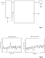
- a load circuit is shown made up by an electric supply line A providing a load current and an electric load 20.
- the supply line A is coupled to a source of alternating electricity (not shown).
- the single supply line A is shown representing a single phase or a three phase system. The functionality of the overload protection device would not be affected by the application in a three phase electrical system.
- the supply line A is connected to a load in form of a motor 20 by a contactor 10 and an overload protection device 30.
- the motor 20 is a fixed speed motor, also described as induction motor, and in principle known since long time.
- the contactor has an internal set of contacts (not shown) coupling the supply line to the overload protection device and the motor.
- the contactor receives an activation signal via a signal line 11 from the overload protection device 30.
- the signal line 11 can be an electric signal path or a mechanical coupling.
- the overload protection device 30 detects an overload situation, it transmits an activation signal to the contactor, as a result of which the internal contacts of the contactor are activated to interrupt the power supply to the motor 20.
- the contactor functionality could be integrated into the overload protection device.
- Fig. 2 shows in a principle block diagram the components of an electronic overload protection device 30 necessary for implementing and understanding the invention.
- the first means 31 are in principle known. It can be for example current transformers, in this case the measurement signal would be a transformer current. In the simplest way it could also be resistors, the measurement signal in this case would be a voltage proportional to the load current.
- the first means 31 can as well comprise a zero crossing determinator, not shown, so that the measurement signal is based on recording the time difference between successive zero crossing times of the load current.
- the zero crossing determinator can be an electronic circuitry or a microprocessor with a functional module for computing the zero crossing times.
- the first means 31 are connected to an overload control circuit 32, which comprises second means 33 for deriving an indicator signal for an overload situation based on the measurement signal.
- the second means 32 are functional units in principle known to be necessary to form an electronic overload protection device or overload protection relay. They comprise a microcontroller, A/D-converter, amplifiers, filter, clock generator, voltage controller, reference voltage source etc.
- the overload protection device 30 further comprises a load diagnostic circuit 34, which is also connected to the first means 31.
- the load diagnostic circuit 34 comprises third means 35 for generating a frequency spectrum of the measurement signal, the third means being for example an FFT (fast Fourier Transform) or DFT (digital Fourier transform) algorithm within the application program of a microprocessor.
- FFT fast Fourier Transform
- DFT digital Fourier transform
- the load diagnostic circuit 34 further comprises fourth means 36 for analysing the frequency spectrum and deriving diagnostic information concerning the condition of the load from the frequency spectrum.
- the fourth means 36 can be realised by a frequency spectrum analyser circuit with additional evaluation logic. As described in more detail below, the ecaluation logic looks at the frequency spectrum an determines if in certain predetermined frequency ranges certain characteristic frequency peaks are detected. If yes, the evaluation logic generates a motor fault signal, which is provided to the outside of the electronic overload protection device via a signal line 42.
- motor controllers and motor protection devices are integrated in a process control system with the help of a fieldbus connection, e.g. Modbus. Via this connection the control system can control the motor from remote and can also read out diagnosis information. So the signal line 42 can also be a fieldbus communication interface.
- the overload control circuit 32 and the load diagnostic circuit 34 are functional blocks physically realised in one microprocessor module 37.
- the load diagnostic function block can be realised by amending the application program of the microcontroller.
- the microprocessor module 37 provides the logic functionality that is needed to realise the overload protection and load diagnosis. It is in this respect comparable to a small PLC (programmable logic controller).
- Figure 3 shows a further embodiment of the invention, wherein the load diagnostic circuit 34 comprises fifth means 38 to derive an analysis signal from the measurement signal.
- the fifth means 38 can be a rectifier or a zero crossing determination circuit.
- an analysis signal derived from the current measurement signal is used to perform the load diagnostic function.
- the analysis signal can be for example the rectified current measurement signal or a signal based on recording the time difference between successive zero crossing times of the load current.
- Figure 4 shows a further embodiment of the invention, wherein the first means 31 comprises a zero crossing determinator 39, so that the measurement signal is based on recording the time difference between successive zero crossing times of the load current.
- Both the overload protection function and the motor diagnosis function is in this embodiment based on an analysis signal derived from the current measurement signal.
- Figure 5 shows a block diagram of a motor controller 41 with an overload control circuit 32, a load diagnostic circuit 34 and a motor control function block 40.
- the motor control function block provides additional motor control functionality to the motor controller 41, it is as well connected to the signal line 42, which can be a fieldbus communication interface.
- the motor control function block 40 can be an additional amendment to the application program of the microprocessor on the microprocessor module 37.
- a broken rotor bar is a common fault in induction motors, lowering the motor efficiency significantly and causing potential hazards of safety. Due to the combination of poor working environment and heavy duty cycles, broken rotor bar faults frequently occur in induction motors. When the bars get cracked at their connecting end rings, they are called broken bars. Detection of such broken rotor bars is highly desired in the industries.
- the amplitudes of these additional frequency components in the stator current are determined by the fault severity (number of broken rotor bars).
- Stator short problem occurs when there is turn-to-turn short-circuit, due to burning and melting of insulation, wires etc, within a coil, coils of same phase or open-circuit in any phase. In these cases, the motor may still continue to operate, but eventually the problems become more intense like phase-to-phase, phase-to-earth short-circuit, and finally the motor stops operating.
- the stator shorts can be detected by locating the appearance of the frequency f st in the frequency spectrum of the stator current.
- the invention principle is concentrated on the frequency spectrum analysis for example using discrete Fourier transform or fast Fourier transform, of the measurement of interest which could be the motor current, rectified version of the motor current or the zero-crossing, measured or computed, of the motor current.
- the key signature for the broken bar and other diagnostics features like shorted stator coil, etc. would be appearance of some frequency peak(s) of increased magnitude in some specified frequency regions which depend on the type of feature to be detected and the kind of measurement (current, rectified current, zero-crossing) used. For healthy motors, such frequency peak(s) in those regions would be absent or the magnitude of the peak(s), i.e. the decibel or dB level, would be lower.
- FIG. 6 The principle is depicted in figure 6 for broken rotor bar detection.
- the right side of fig. 6 shows the frequency spectrum of the motor current in the range between 1 and 10 Hz, for a motor with no broken bars. No significant peak can be seen in the spectrum.
- the left side of fig. 6 shows the frequency spectrum in the same frequency range, this time for a motor with a broken bar. A significant peak appears at around 4.5 Hz. The occurrence of such a peak in the frequency spectrum thus can be used as indicator for a broken rotor bar.
Landscapes
- Protection Of Generators And Motors (AREA)
Claims (11)
- Dispositif de protection contre les surcharges (30) destiné à protéger une charge électrique (20), particulièrement un moteur à induction (20), dans un circuit de charge composé par une ligne d'alimentation électrique (A) fournissant un courant de charge et la charge électrique (20), le dispositif comprenant- un premier moyen (31) configuré pour dériver un signal de mesure correspondant au courant de charge,- un circuit de contrôle de surcharge (32) configuré pour déterminer une situation de surcharge, le circuit de contrôle de surcharge comprenant- un deuxième moyen configuré pour dériver un signal indicateur d'une situation de surcharge en fonction du signal de mesure,ledit dispositif de protection contre les surcharges (30) comprenant en outre- un circuit de diagnostic de charge (34), le circuit de diagnostic de charge (34) comprenantdans lequel le troisième moyen (35) est configuré pour exécuter une transformation de Fourier discrète, DFT, ou une transformation de Fourier rapide, FFT, du signal de mesure ou d'un signal d'analyse dérivé à partir du signal de mesure,- un cinquième moyen (38) configuré pour dériver un signal d'analyse à partir du signal de mesure,- un troisième moyen (35) configuré pour générer un spectre de fréquences du signal d'analyse dérivé à partir du signal de mesure,- un quatrième moyen (36) configuré pour analyser ledit spectre de fréquences et configuré pour dériver des informations de diagnostic concernant l'état de la charge à partir du spectre de fréquences,
dans lequel le quatrième moyen (36) est configuré pour déterminer l'aspect d'un pic de fréquence d'une grandeur accrue dans une région de fréquence prédéterminée du spectre de fréquences du signal d'analyse dérivé à partir du signal de mesure, lequel dépend du type de caractéristique à détecter. - Dispositif selon la revendication 1, dans lequel le cinquième moyen (38) comprend un redresseur de telle sorte que le signal d'analyse corresponde au courant de charge redressé.
- Dispositif selon la revendication 1, dans lequel le cinquième moyen (38) comprend un déterminateur de franchissements du zéro de telle sorte que le signal d'analyse soit basé sur un enregistrement de la différence de temps entre des temps de franchissement du zéro successifs du courant de charge.
- Dispositif selon la revendication 1, dans lequel le premier moyen (31) comprend un déterminateur de franchissements du zéro (39) de telle sorte que le signal de mesure soit basé sur l'enregistrement de la différence de temps entre des temps de franchissement du zéro successifs du courant de charge.
- Dispositif selon la revendication 1, le dispositif comprenant un microprocesseur (37) et dans lequel le circuit de diagnostic de charge (34) est réalisé en tant qu'au moins un module logiciel fonctionnel dans le programme d'application du microprocesseur (35).
- Unité de commande de moteur (40), fournissant des fonctions de commande de moteur et de protection de moteur, comprenant un dispositif de protection contre les surcharges (30) selon la revendication 1.
- Procédé destiné à être utilisé avec un dispositif de protection contre les surcharges afin de protéger une charge électrique, particulièrement un moteur à induction, dans un circuit de charge, le circuit de charge étant composé par une ligne d'alimentation électrique fournissant un courant de charge, et la charge électrique, le dispositif de protection contre les surcharges fournissant un signal de mesure correspondant au courant de charge et un signal d'analyses dérivé à partir du signal de mesure, dans lequel le signal d'analyse dérivé à partir du signal de mesure est basé sur un enregistrement de la différence de temps entre des temps de franchissement du zéro successifs du courant de charge, le procédé comprenant les étapes de :- génération d'un spectre de fréquences du signal d'analyse,- analyse dudit spectre de fréquences, pour détecter l'aspect d'un pic de fréquence dans une région de fréquence prédéterminée du spectre de fréquences, le pic de fréquence étant une caractéristique de défauts spécifiques dans le circuit de charge, et- production d'un signal indicateur de défauts, indicatif de défauts spécifiques en fonction de la fréquence du pic.
- Procédé selon la revendication 7, dans lequel un signal indiquant l'occurrence d'une barre rotorique cassée dans un moteur à induction est produit si des pics dans le spectre de fréquences sont détectés à des fréquences fbrb :

- Procédé selon la revendication 7, dans lequel un signal indiquant l'occurrence d'un court-circuit d'enroulement est produit si des pics dans le spectre de fréquences sont détectés à des fréquences fst :

- Programme informatique à code de programme configuré pour exécuter le procédé selon la revendication 7, si le programme est exécuté sur un ordinateur ou microprocesseur.
- Produit de programme informatique à code de programme configuré pour exécuter le procédé selon la revendication 7, si le programme est exécuté sur un ordinateur ou microprocesseur.
Priority Applications (2)
| Application Number | Priority Date | Filing Date | Title |
|---|---|---|---|
| EP09004087.4A EP2234236B1 (fr) | 2009-03-23 | 2009-03-23 | Relais de surcharge thermique avec diagnostics de moteur |
| EP09010147A EP2290776A1 (fr) | 2009-03-23 | 2009-08-06 | Relais de surcharge thermique avec fonctions de protection basées sur la tension |
Applications Claiming Priority (1)
| Application Number | Priority Date | Filing Date | Title |
|---|---|---|---|
| EP09004087.4A EP2234236B1 (fr) | 2009-03-23 | 2009-03-23 | Relais de surcharge thermique avec diagnostics de moteur |
Publications (2)
| Publication Number | Publication Date |
|---|---|
| EP2234236A1 EP2234236A1 (fr) | 2010-09-29 |
| EP2234236B1 true EP2234236B1 (fr) | 2018-05-23 |
Family
ID=40757025
Family Applications (1)
| Application Number | Title | Priority Date | Filing Date |
|---|---|---|---|
| EP09004087.4A Active EP2234236B1 (fr) | 2009-03-23 | 2009-03-23 | Relais de surcharge thermique avec diagnostics de moteur |
Country Status (1)
| Country | Link |
|---|---|
| EP (1) | EP2234236B1 (fr) |
Family Cites Families (5)
| Publication number | Priority date | Publication date | Assignee | Title |
|---|---|---|---|---|
| US5301123A (en) * | 1990-01-30 | 1994-04-05 | Board Of Governors For Higher Education, State Of Rhode Island And Providence Plantations | Zero crossing based spectrum analyzer and method |
| CA2050223C (fr) | 1990-09-27 | 1995-10-10 | Richard W. Waltz | Dispositif de protection contre les courants de surcharge |
| DE19748627B4 (de) | 1997-11-04 | 2013-07-18 | Abb Ag | Elektronisches Überlastrelais |
| US6289735B1 (en) * | 1998-09-29 | 2001-09-18 | Reliance Electric Technologies, Llc | Machine diagnostic system and method for vibration analysis |
| US7231319B2 (en) * | 2003-06-18 | 2007-06-12 | Eaton Corporation | System and method for proactive motor wellness diagnosis based on potential cavitation faults |
-
2009
- 2009-03-23 EP EP09004087.4A patent/EP2234236B1/fr active Active
Non-Patent Citations (1)
| Title |
|---|
| None * |
Also Published As
| Publication number | Publication date |
|---|---|
| EP2234236A1 (fr) | 2010-09-29 |
Similar Documents
| Publication | Publication Date | Title |
|---|---|---|
| AU2020365367B2 (en) | Fault detection in synchronous machines | |
| EP3268760B1 (fr) | Dispositif de surveillance de terre neutre de générateur à l'aide d'une mesure et d'une analyse de composantes de courant continu | |
| Filippetti et al. | Condition monitoring and diagnosis of rotor faults in induction machines: State of art and future perspectives | |
| US7253634B1 (en) | Generator protection methods and systems self-tuning to a plurality of characteristics of a machine | |
| EP2730023B1 (fr) | Système, produit de programme informatique et procédé de détection des défauts d'enroulement internes d'un générateur synchrone | |
| TWI506906B (zh) | 用以提供電能的裝置及方法與相關之系統 | |
| US7480124B2 (en) | Detection of an AC input phase-loss on a multi-phase AC servo drive | |
| US9151802B2 (en) | Detection of broken rotor bar conditions in a motor using maximum current magnitude and average current magnitude | |
| EP2290776A1 (fr) | Relais de surcharge thermique avec fonctions de protection basées sur la tension | |
| US7042229B2 (en) | System and method for on line monitoring of insulation condition for DC machines | |
| EP2641099B1 (fr) | Système de surveillance de la fatigue d'un câble et son procédé | |
| CN105737903A (zh) | 港口机械设备故障智能预诊断及维保智能预警方法 | |
| CN109564257A (zh) | 在稳态期间使用行波进行的故障检测和保护 | |
| Durocher et al. | Predictive Versus Preventive Maintenance: Future Control Technologies in Motor Diagnosis and System Wellness | |
| EP2851698B1 (fr) | Procédé de détection d'une panne d'une machine électrique | |
| AU2013337038A1 (en) | A method for the diagnostics of electromechanical system based on impedance analysis | |
| WO2018142569A1 (fr) | Dispositif de diagnostic de moteur | |
| Irfan et al. | Development of an intelligent condition monitoring system for AC induction motors using PLC | |
| Thomson et al. | Industrial application of current signature analysis to diagnose faults in 3-phase squirrel cage induction motors | |
| EP3648336B1 (fr) | Protection de courant différentiel d'enroulement parallèle de moteur et procedure associe | |
| Ehya et al. | Detailed magnetic field monitoring of short circuit defects of excitation winding in hydro-generator | |
| CN103403564B (zh) | 用于接地故障检测适配的方法 | |
| EP2234236B1 (fr) | Relais de surcharge thermique avec diagnostics de moteur | |
| EP2264850A2 (fr) | Relais de surcharge thermique avec classification de déclenchement | |
| Bengtsson et al. | Power transformer performance monitoring presented in SCADA |
Legal Events
| Date | Code | Title | Description |
|---|---|---|---|
| PUAI | Public reference made under article 153(3) epc to a published international application that has entered the european phase |
Free format text: ORIGINAL CODE: 0009012 |
|
| AK | Designated contracting states |
Kind code of ref document: A1 Designated state(s): AT BE BG CH CY CZ DE DK EE ES FI FR GB GR HR HU IE IS IT LI LT LU LV MC MK MT NL NO PL PT RO SE SI SK TR |
|
| AX | Request for extension of the european patent |
Extension state: AL BA RS |
|
| 17P | Request for examination filed |
Effective date: 20101207 |
|
| 17Q | First examination report despatched |
Effective date: 20110217 |
|
| AKX | Designation fees paid |
Designated state(s): AT BE BG CH CY CZ DE DK EE ES FI FR GB GR HR HU IE IS IT LI LT LU LV MC MK MT NL NO PL PT RO SE SI SK TR |
|
| GRAP | Despatch of communication of intention to grant a patent |
Free format text: ORIGINAL CODE: EPIDOSNIGR1 |
|
| STAA | Information on the status of an ep patent application or granted ep patent |
Free format text: STATUS: GRANT OF PATENT IS INTENDED |
|
| INTG | Intention to grant announced |
Effective date: 20180226 |
|
| RIN1 | Information on inventor provided before grant (corrected) |
Inventor name: ANDENNA, ANDREA Inventor name: ORKISZ, MICHAEL, DR. Inventor name: UKIL, ABHISEK Inventor name: MUELLER, PETER O. |
|
| GRAS | Grant fee paid |
Free format text: ORIGINAL CODE: EPIDOSNIGR3 |
|
| GRAA | (expected) grant |
Free format text: ORIGINAL CODE: 0009210 |
|
| STAA | Information on the status of an ep patent application or granted ep patent |
Free format text: STATUS: THE PATENT HAS BEEN GRANTED |
|
| AK | Designated contracting states |
Kind code of ref document: B1 Designated state(s): AT BE BG CH CY CZ DE DK EE ES FI FR GB GR HR HU IE IS IT LI LT LU LV MC MK MT NL NO PL PT RO SE SI SK TR |
|
| REG | Reference to a national code |
Ref country code: GB Ref legal event code: FG4D |
|
| REG | Reference to a national code |
Ref country code: CH Ref legal event code: EP |
|
| REG | Reference to a national code |
Ref country code: IE Ref legal event code: FG4D |
|
| REG | Reference to a national code |
Ref country code: AT Ref legal event code: REF Ref document number: 1002286 Country of ref document: AT Kind code of ref document: T Effective date: 20180615 |
|
| REG | Reference to a national code |
Ref country code: DE Ref legal event code: R096 Ref document number: 602009052404 Country of ref document: DE |
|
| REG | Reference to a national code |
Ref country code: NL Ref legal event code: MP Effective date: 20180523 |
|
| REG | Reference to a national code |
Ref country code: LT Ref legal event code: MG4D |
|
| PG25 | Lapsed in a contracting state [announced via postgrant information from national office to epo] |
Ref country code: NO Free format text: LAPSE BECAUSE OF FAILURE TO SUBMIT A TRANSLATION OF THE DESCRIPTION OR TO PAY THE FEE WITHIN THE PRESCRIBED TIME-LIMIT Effective date: 20180823 Ref country code: FI Free format text: LAPSE BECAUSE OF FAILURE TO SUBMIT A TRANSLATION OF THE DESCRIPTION OR TO PAY THE FEE WITHIN THE PRESCRIBED TIME-LIMIT Effective date: 20180523 Ref country code: BG Free format text: LAPSE BECAUSE OF FAILURE TO SUBMIT A TRANSLATION OF THE DESCRIPTION OR TO PAY THE FEE WITHIN THE PRESCRIBED TIME-LIMIT Effective date: 20180823 Ref country code: LT Free format text: LAPSE BECAUSE OF FAILURE TO SUBMIT A TRANSLATION OF THE DESCRIPTION OR TO PAY THE FEE WITHIN THE PRESCRIBED TIME-LIMIT Effective date: 20180523 Ref country code: ES Free format text: LAPSE BECAUSE OF FAILURE TO SUBMIT A TRANSLATION OF THE DESCRIPTION OR TO PAY THE FEE WITHIN THE PRESCRIBED TIME-LIMIT Effective date: 20180523 Ref country code: SE Free format text: LAPSE BECAUSE OF FAILURE TO SUBMIT A TRANSLATION OF THE DESCRIPTION OR TO PAY THE FEE WITHIN THE PRESCRIBED TIME-LIMIT Effective date: 20180523 |
|
| PG25 | Lapsed in a contracting state [announced via postgrant information from national office to epo] |
Ref country code: LV Free format text: LAPSE BECAUSE OF FAILURE TO SUBMIT A TRANSLATION OF THE DESCRIPTION OR TO PAY THE FEE WITHIN THE PRESCRIBED TIME-LIMIT Effective date: 20180523 Ref country code: HR Free format text: LAPSE BECAUSE OF FAILURE TO SUBMIT A TRANSLATION OF THE DESCRIPTION OR TO PAY THE FEE WITHIN THE PRESCRIBED TIME-LIMIT Effective date: 20180523 Ref country code: GR Free format text: LAPSE BECAUSE OF FAILURE TO SUBMIT A TRANSLATION OF THE DESCRIPTION OR TO PAY THE FEE WITHIN THE PRESCRIBED TIME-LIMIT Effective date: 20180824 Ref country code: NL Free format text: LAPSE BECAUSE OF FAILURE TO SUBMIT A TRANSLATION OF THE DESCRIPTION OR TO PAY THE FEE WITHIN THE PRESCRIBED TIME-LIMIT Effective date: 20180523 |
|
| REG | Reference to a national code |
Ref country code: AT Ref legal event code: MK05 Ref document number: 1002286 Country of ref document: AT Kind code of ref document: T Effective date: 20180523 |
|
| PG25 | Lapsed in a contracting state [announced via postgrant information from national office to epo] |
Ref country code: PL Free format text: LAPSE BECAUSE OF FAILURE TO SUBMIT A TRANSLATION OF THE DESCRIPTION OR TO PAY THE FEE WITHIN THE PRESCRIBED TIME-LIMIT Effective date: 20180523 Ref country code: DK Free format text: LAPSE BECAUSE OF FAILURE TO SUBMIT A TRANSLATION OF THE DESCRIPTION OR TO PAY THE FEE WITHIN THE PRESCRIBED TIME-LIMIT Effective date: 20180523 Ref country code: SK Free format text: LAPSE BECAUSE OF FAILURE TO SUBMIT A TRANSLATION OF THE DESCRIPTION OR TO PAY THE FEE WITHIN THE PRESCRIBED TIME-LIMIT Effective date: 20180523 Ref country code: RO Free format text: LAPSE BECAUSE OF FAILURE TO SUBMIT A TRANSLATION OF THE DESCRIPTION OR TO PAY THE FEE WITHIN THE PRESCRIBED TIME-LIMIT Effective date: 20180523 Ref country code: CZ Free format text: LAPSE BECAUSE OF FAILURE TO SUBMIT A TRANSLATION OF THE DESCRIPTION OR TO PAY THE FEE WITHIN THE PRESCRIBED TIME-LIMIT Effective date: 20180523 Ref country code: EE Free format text: LAPSE BECAUSE OF FAILURE TO SUBMIT A TRANSLATION OF THE DESCRIPTION OR TO PAY THE FEE WITHIN THE PRESCRIBED TIME-LIMIT Effective date: 20180523 Ref country code: AT Free format text: LAPSE BECAUSE OF FAILURE TO SUBMIT A TRANSLATION OF THE DESCRIPTION OR TO PAY THE FEE WITHIN THE PRESCRIBED TIME-LIMIT Effective date: 20180523 |
|
| REG | Reference to a national code |
Ref country code: DE Ref legal event code: R097 Ref document number: 602009052404 Country of ref document: DE |
|
| PLBE | No opposition filed within time limit |
Free format text: ORIGINAL CODE: 0009261 |
|
| STAA | Information on the status of an ep patent application or granted ep patent |
Free format text: STATUS: NO OPPOSITION FILED WITHIN TIME LIMIT |
|
| 26N | No opposition filed |
Effective date: 20190226 |
|
| PG25 | Lapsed in a contracting state [announced via postgrant information from national office to epo] |
Ref country code: SI Free format text: LAPSE BECAUSE OF FAILURE TO SUBMIT A TRANSLATION OF THE DESCRIPTION OR TO PAY THE FEE WITHIN THE PRESCRIBED TIME-LIMIT Effective date: 20180523 |
|
| PG25 | Lapsed in a contracting state [announced via postgrant information from national office to epo] |
Ref country code: MC Free format text: LAPSE BECAUSE OF FAILURE TO SUBMIT A TRANSLATION OF THE DESCRIPTION OR TO PAY THE FEE WITHIN THE PRESCRIBED TIME-LIMIT Effective date: 20180523 |
|
| REG | Reference to a national code |
Ref country code: CH Ref legal event code: PL |
|
| GBPC | Gb: european patent ceased through non-payment of renewal fee |
Effective date: 20190323 |
|
| PG25 | Lapsed in a contracting state [announced via postgrant information from national office to epo] |
Ref country code: LU Free format text: LAPSE BECAUSE OF NON-PAYMENT OF DUE FEES Effective date: 20190323 |
|
| REG | Reference to a national code |
Ref country code: BE Ref legal event code: MM Effective date: 20190331 |
|
| REG | Reference to a national code |
Ref country code: DE Ref legal event code: R081 Ref document number: 602009052404 Country of ref document: DE Owner name: ABB SCHWEIZ AG, CH Free format text: FORMER OWNER: ABB AG, 68165 MANNHEIM, DE |
|
| PG25 | Lapsed in a contracting state [announced via postgrant information from national office to epo] |
Ref country code: GB Free format text: LAPSE BECAUSE OF NON-PAYMENT OF DUE FEES Effective date: 20190323 Ref country code: IE Free format text: LAPSE BECAUSE OF NON-PAYMENT OF DUE FEES Effective date: 20190323 Ref country code: CH Free format text: LAPSE BECAUSE OF NON-PAYMENT OF DUE FEES Effective date: 20190331 Ref country code: LI Free format text: LAPSE BECAUSE OF NON-PAYMENT OF DUE FEES Effective date: 20190331 |
|
| PG25 | Lapsed in a contracting state [announced via postgrant information from national office to epo] |
Ref country code: BE Free format text: LAPSE BECAUSE OF NON-PAYMENT OF DUE FEES Effective date: 20190331 |
|
| PG25 | Lapsed in a contracting state [announced via postgrant information from national office to epo] |
Ref country code: TR Free format text: LAPSE BECAUSE OF FAILURE TO SUBMIT A TRANSLATION OF THE DESCRIPTION OR TO PAY THE FEE WITHIN THE PRESCRIBED TIME-LIMIT Effective date: 20180523 |
|
| PG25 | Lapsed in a contracting state [announced via postgrant information from national office to epo] |
Ref country code: PT Free format text: LAPSE BECAUSE OF FAILURE TO SUBMIT A TRANSLATION OF THE DESCRIPTION OR TO PAY THE FEE WITHIN THE PRESCRIBED TIME-LIMIT Effective date: 20180924 Ref country code: MT Free format text: LAPSE BECAUSE OF NON-PAYMENT OF DUE FEES Effective date: 20190323 |
|
| PG25 | Lapsed in a contracting state [announced via postgrant information from national office to epo] |
Ref country code: CY Free format text: LAPSE BECAUSE OF FAILURE TO SUBMIT A TRANSLATION OF THE DESCRIPTION OR TO PAY THE FEE WITHIN THE PRESCRIBED TIME-LIMIT Effective date: 20180523 |
|
| PG25 | Lapsed in a contracting state [announced via postgrant information from national office to epo] |
Ref country code: IS Free format text: LAPSE BECAUSE OF FAILURE TO SUBMIT A TRANSLATION OF THE DESCRIPTION OR TO PAY THE FEE WITHIN THE PRESCRIBED TIME-LIMIT Effective date: 20180923 |
|
| PG25 | Lapsed in a contracting state [announced via postgrant information from national office to epo] |
Ref country code: HU Free format text: LAPSE BECAUSE OF FAILURE TO SUBMIT A TRANSLATION OF THE DESCRIPTION OR TO PAY THE FEE WITHIN THE PRESCRIBED TIME-LIMIT; INVALID AB INITIO Effective date: 20090323 |
|
| PG25 | Lapsed in a contracting state [announced via postgrant information from national office to epo] |
Ref country code: MK Free format text: LAPSE BECAUSE OF FAILURE TO SUBMIT A TRANSLATION OF THE DESCRIPTION OR TO PAY THE FEE WITHIN THE PRESCRIBED TIME-LIMIT Effective date: 20180523 |
|
| PGFP | Annual fee paid to national office [announced via postgrant information from national office to epo] |
Ref country code: DE Payment date: 20260319 Year of fee payment: 18 |
|
| PGFP | Annual fee paid to national office [announced via postgrant information from national office to epo] |
Ref country code: IT Payment date: 20260324 Year of fee payment: 18 |
|
| PGFP | Annual fee paid to national office [announced via postgrant information from national office to epo] |
Ref country code: FR Payment date: 20260320 Year of fee payment: 18 |