EP2235335B1 - Wärmeenergie enthaltende anordnung für eine abgasreinigungsvorrichtung - Google Patents
Wärmeenergie enthaltende anordnung für eine abgasreinigungsvorrichtung Download PDFInfo
- Publication number
- EP2235335B1 EP2235335B1 EP07870465A EP07870465A EP2235335B1 EP 2235335 B1 EP2235335 B1 EP 2235335B1 EP 07870465 A EP07870465 A EP 07870465A EP 07870465 A EP07870465 A EP 07870465A EP 2235335 B1 EP2235335 B1 EP 2235335B1
- Authority
- EP
- European Patent Office
- Prior art keywords
- thermal energy
- purification device
- energy containing
- exhaust gas
- containing means
- Prior art date
- Legal status (The legal status is an assumption and is not a legal conclusion. Google has not performed a legal analysis and makes no representation as to the accuracy of the status listed.)
- Active
Links
Images
Classifications
-
- F—MECHANICAL ENGINEERING; LIGHTING; HEATING; WEAPONS; BLASTING
- F01—MACHINES OR ENGINES IN GENERAL; ENGINE PLANTS IN GENERAL; STEAM ENGINES
- F01N—GAS-FLOW SILENCERS OR EXHAUST APPARATUS FOR MACHINES OR ENGINES IN GENERAL; GAS-FLOW SILENCERS OR EXHAUST APPARATUS FOR INTERNAL-COMBUSTION ENGINES
- F01N3/00—Exhaust or silencing apparatus having means for purifying, rendering innocuous, or otherwise treating exhaust
- F01N3/08—Exhaust or silencing apparatus having means for purifying, rendering innocuous, or otherwise treating exhaust for rendering innocuous
- F01N3/10—Exhaust or silencing apparatus having means for purifying, rendering innocuous, or otherwise treating exhaust for rendering innocuous by thermal or catalytic conversion of noxious components of exhaust
- F01N3/18—Exhaust or silencing apparatus having means for purifying, rendering innocuous, or otherwise treating exhaust for rendering innocuous by thermal or catalytic conversion of noxious components of exhaust characterised by methods of operation; Control
- F01N3/20—Exhaust or silencing apparatus having means for purifying, rendering innocuous, or otherwise treating exhaust for rendering innocuous by thermal or catalytic conversion of noxious components of exhaust characterised by methods of operation; Control specially adapted for catalytic conversion
- F01N3/2006—Periodically heating or cooling catalytic reactors, e.g. at cold starting or overheating
-
- F—MECHANICAL ENGINEERING; LIGHTING; HEATING; WEAPONS; BLASTING
- F01—MACHINES OR ENGINES IN GENERAL; ENGINE PLANTS IN GENERAL; STEAM ENGINES
- F01N—GAS-FLOW SILENCERS OR EXHAUST APPARATUS FOR MACHINES OR ENGINES IN GENERAL; GAS-FLOW SILENCERS OR EXHAUST APPARATUS FOR INTERNAL-COMBUSTION ENGINES
- F01N13/00—Exhaust or silencing apparatus characterised by constructional features
- F01N13/14—Exhaust or silencing apparatus characterised by constructional features having thermal insulation
-
- F—MECHANICAL ENGINEERING; LIGHTING; HEATING; WEAPONS; BLASTING
- F01—MACHINES OR ENGINES IN GENERAL; ENGINE PLANTS IN GENERAL; STEAM ENGINES
- F01N—GAS-FLOW SILENCERS OR EXHAUST APPARATUS FOR MACHINES OR ENGINES IN GENERAL; GAS-FLOW SILENCERS OR EXHAUST APPARATUS FOR INTERNAL-COMBUSTION ENGINES
- F01N3/00—Exhaust or silencing apparatus having means for purifying, rendering innocuous, or otherwise treating exhaust
- F01N3/02—Exhaust or silencing apparatus having means for purifying, rendering innocuous, or otherwise treating exhaust for cooling, or for removing solid constituents of, exhaust
- F01N3/021—Exhaust or silencing apparatus having means for purifying, rendering innocuous, or otherwise treating exhaust for cooling, or for removing solid constituents of, exhaust by means of filters
- F01N3/031—Exhaust or silencing apparatus having means for purifying, rendering innocuous, or otherwise treating exhaust for cooling, or for removing solid constituents of, exhaust by means of filters having means for by-passing filters, e.g. when clogged or during cold engine start
-
- F—MECHANICAL ENGINEERING; LIGHTING; HEATING; WEAPONS; BLASTING
- F01—MACHINES OR ENGINES IN GENERAL; ENGINE PLANTS IN GENERAL; STEAM ENGINES
- F01N—GAS-FLOW SILENCERS OR EXHAUST APPARATUS FOR MACHINES OR ENGINES IN GENERAL; GAS-FLOW SILENCERS OR EXHAUST APPARATUS FOR INTERNAL-COMBUSTION ENGINES
- F01N3/00—Exhaust or silencing apparatus having means for purifying, rendering innocuous, or otherwise treating exhaust
- F01N3/08—Exhaust or silencing apparatus having means for purifying, rendering innocuous, or otherwise treating exhaust for rendering innocuous
- F01N3/10—Exhaust or silencing apparatus having means for purifying, rendering innocuous, or otherwise treating exhaust for rendering innocuous by thermal or catalytic conversion of noxious components of exhaust
- F01N3/24—Exhaust or silencing apparatus having means for purifying, rendering innocuous, or otherwise treating exhaust for rendering innocuous by thermal or catalytic conversion of noxious components of exhaust characterised by constructional aspects of converting apparatus
-
- F—MECHANICAL ENGINEERING; LIGHTING; HEATING; WEAPONS; BLASTING
- F01—MACHINES OR ENGINES IN GENERAL; ENGINE PLANTS IN GENERAL; STEAM ENGINES
- F01N—GAS-FLOW SILENCERS OR EXHAUST APPARATUS FOR MACHINES OR ENGINES IN GENERAL; GAS-FLOW SILENCERS OR EXHAUST APPARATUS FOR INTERNAL-COMBUSTION ENGINES
- F01N3/00—Exhaust or silencing apparatus having means for purifying, rendering innocuous, or otherwise treating exhaust
- F01N3/08—Exhaust or silencing apparatus having means for purifying, rendering innocuous, or otherwise treating exhaust for rendering innocuous
- F01N3/10—Exhaust or silencing apparatus having means for purifying, rendering innocuous, or otherwise treating exhaust for rendering innocuous by thermal or catalytic conversion of noxious components of exhaust
- F01N3/24—Exhaust or silencing apparatus having means for purifying, rendering innocuous, or otherwise treating exhaust for rendering innocuous by thermal or catalytic conversion of noxious components of exhaust characterised by constructional aspects of converting apparatus
- F01N3/28—Construction of catalytic reactors
- F01N3/2892—Exhaust flow directors or the like, e.g. upstream of catalytic device
-
- F—MECHANICAL ENGINEERING; LIGHTING; HEATING; WEAPONS; BLASTING
- F01—MACHINES OR ENGINES IN GENERAL; ENGINE PLANTS IN GENERAL; STEAM ENGINES
- F01N—GAS-FLOW SILENCERS OR EXHAUST APPARATUS FOR MACHINES OR ENGINES IN GENERAL; GAS-FLOW SILENCERS OR EXHAUST APPARATUS FOR INTERNAL-COMBUSTION ENGINES
- F01N2240/00—Combination or association of two or more different exhaust treating devices, or of at least one such device with an auxiliary device, not covered by indexing codes F01N2230/00 or F01N2250/00, one of the devices being
- F01N2240/10—Combination or association of two or more different exhaust treating devices, or of at least one such device with an auxiliary device, not covered by indexing codes F01N2230/00 or F01N2250/00, one of the devices being a heat accumulator
-
- F—MECHANICAL ENGINEERING; LIGHTING; HEATING; WEAPONS; BLASTING
- F01—MACHINES OR ENGINES IN GENERAL; ENGINE PLANTS IN GENERAL; STEAM ENGINES
- F01N—GAS-FLOW SILENCERS OR EXHAUST APPARATUS FOR MACHINES OR ENGINES IN GENERAL; GAS-FLOW SILENCERS OR EXHAUST APPARATUS FOR INTERNAL-COMBUSTION ENGINES
- F01N2240/00—Combination or association of two or more different exhaust treating devices, or of at least one such device with an auxiliary device, not covered by indexing codes F01N2230/00 or F01N2250/00, one of the devices being
- F01N2240/20—Combination or association of two or more different exhaust treating devices, or of at least one such device with an auxiliary device, not covered by indexing codes F01N2230/00 or F01N2250/00, one of the devices being a flow director or deflector
-
- F—MECHANICAL ENGINEERING; LIGHTING; HEATING; WEAPONS; BLASTING
- F01—MACHINES OR ENGINES IN GENERAL; ENGINE PLANTS IN GENERAL; STEAM ENGINES
- F01N—GAS-FLOW SILENCERS OR EXHAUST APPARATUS FOR MACHINES OR ENGINES IN GENERAL; GAS-FLOW SILENCERS OR EXHAUST APPARATUS FOR INTERNAL-COMBUSTION ENGINES
- F01N2260/00—Exhaust treating devices having provisions not otherwise provided for
- F01N2260/08—Exhaust treating devices having provisions not otherwise provided for for preventing heat loss or temperature drop, using other means than layers of heat-insulating material
-
- F—MECHANICAL ENGINEERING; LIGHTING; HEATING; WEAPONS; BLASTING
- F01—MACHINES OR ENGINES IN GENERAL; ENGINE PLANTS IN GENERAL; STEAM ENGINES
- F01N—GAS-FLOW SILENCERS OR EXHAUST APPARATUS FOR MACHINES OR ENGINES IN GENERAL; GAS-FLOW SILENCERS OR EXHAUST APPARATUS FOR INTERNAL-COMBUSTION ENGINES
- F01N2260/00—Exhaust treating devices having provisions not otherwise provided for
- F01N2260/14—Exhaust treating devices having provisions not otherwise provided for for modifying or adapting flow area or back-pressure
-
- F—MECHANICAL ENGINEERING; LIGHTING; HEATING; WEAPONS; BLASTING
- F01—MACHINES OR ENGINES IN GENERAL; ENGINE PLANTS IN GENERAL; STEAM ENGINES
- F01N—GAS-FLOW SILENCERS OR EXHAUST APPARATUS FOR MACHINES OR ENGINES IN GENERAL; GAS-FLOW SILENCERS OR EXHAUST APPARATUS FOR INTERNAL-COMBUSTION ENGINES
- F01N2390/00—Arrangements for controlling or regulating exhaust apparatus
-
- Y—GENERAL TAGGING OF NEW TECHNOLOGICAL DEVELOPMENTS; GENERAL TAGGING OF CROSS-SECTIONAL TECHNOLOGIES SPANNING OVER SEVERAL SECTIONS OF THE IPC; TECHNICAL SUBJECTS COVERED BY FORMER USPC CROSS-REFERENCE ART COLLECTIONS [XRACs] AND DIGESTS
- Y02—TECHNOLOGIES OR APPLICATIONS FOR MITIGATION OR ADAPTATION AGAINST CLIMATE CHANGE
- Y02T—CLIMATE CHANGE MITIGATION TECHNOLOGIES RELATED TO TRANSPORTATION
- Y02T10/00—Road transport of goods or passengers
- Y02T10/10—Internal combustion engine [ICE] based vehicles
- Y02T10/12—Improving ICE efficiencies
Definitions
- the invention concerns a thermal energy containing arrangement for an exhaust gas purification device.
- a catalytic converter is an exhaust gas purification device that can be found on an exhaust line. In the catalytic converter, takes place an oxidation/reduction reaction that reduces undesirable emissions of hydrocarbon (HC) and/or carbon monoxide (CO) and/or nitrogen oxide (NOx).
- HC hydrocarbon
- CO carbon monoxide
- NOx nitrogen oxide
- a catalytic converter has to operate within a high temperature range that can be in an area of 200°C/400°C as the catalytic conversion of pollutant requires thermal energy.
- This temperature range is a necessary condition for an efficient oxidation/reduction reaction. This range of temperature is only achieved when an engine has been running for a certain amount of time; after this amount of time, the engine reaches its operating temperature where the exhaust gas are emitted at a high temperature that allows an efficient operation of the catalytic converter.
- a diesel particulate filter regenerates unburnt particulates that are found in exhaust gas. Polluting particulates are collected in a filter and, thus, are not rejected into the atmosphere. In a process known as filter regeneration, accumulated particulates are burnt when the filter load reaches a predetermined level. For the filter regeneration operation, the filter can be heated at a temperature leading to combustion of the particulates within a high temperature range of 500°C/650°C. There again, when an engine is not running at a sufficiently high temperature, filter regeneration may not be complete or may require additional thermal energy.
- Short journeys may not permit an engine to reach a temperature high enough for an efficient operation of the exhaust gas purification device.
- hybrid vehicles which combine an internal combustion engine and one or more electric motors powered by rechargeable batteries.
- the internal combustion engine can be turned off when the vehicle is coasting, braking or stopped (for example, when the vehicle is idling at a traffic light or in traffic congestion) and the engine can be restarted when propulsion is needed.
- this type of vehicles has an impact on the environment that is more favourable than the impact of a conventional vehicle, the amount of times the engine switches off and on may be detrimental for an efficient operation of the depollutionng equipment that cleanses the exhaust gas rejected by the internal combustion engine as high exhaust gas temperatures will never be reached.
- an object of the Invention is to provide an arrangement for an exhaust gas purification device that can offer a better use of the thermal energy generated by an internal combustion engine.
- a thermal energy containment arrangement for an exhaust gas purification device incorporated in an exhaust line of an internal combustion engine the purification device having an inlet port through which exhaust gas from the internal combustion engine can flow in and an outlet port through which the treated exhaust gas can flow out.
- Said arrangement includes a retractable upstream thermal energy containing means located upstream of the purification device and a retractable downstream thermal energy containing means located downstream of the purification device and an actuating means for controlling the position of the said upstream thermal energy containing means and of the said downstream thermal energy containing means within regard to respectively the inlet port and the outlet port of the purification device, the upstream thermal energy containing means and the downstream thermal energy containing means being movable between (i) an engine running position wherein the upstream thermal energy containing means and the downstream thermal energy containing means are in an, at least partially, retracted position and allow the flow of exhaust gas in and out of the depolluting means and (ii) a thermal energy preserving position wherein at least one of the upstream thermal energy containing means and of the downstream thermal energy containing means shut off respectively the inlet port and outlet port of the purification device.
- an engine running position wherein the upstream thermal energy containing means and the downstream thermal energy containing means are in an, at least partially, retracted position and allow the
- the arrangement makes it possible to restrict the inlet and outlet port of the catalytic converter so that the flow of exhaust gases can be focused on a restricted section of the catalytic converter.
- the invention provides an arrangement that makes it possible to partially or entirely isolate an exhaust gas purification device. Therefore, the arrangement according to the invention makes it possible, when an internal combustion engine is turned off, to maintain the thermal energy that has been stored into the purification device while the internal combustion engine was in operation. Unlike a conventional exhaust line wherein the thermal energy that is stored in a purification device starts dissipating as soon as the internal combustion engine is turned off, the arrangement of the invention makes it possible to maintain the temperature of the purification device. In this way, as soon as the engine restarts, the purification device can Immediately resume operation as the purification device is at a temperature level that authorizes an efficient purification treatment.
- the arrangement according to the invention brings a substantial advantage to any vehicle powered by an internal combustion engine, it can be pointed out that the arrangement according to the invention can be successfully implemented on a hybrid vehicle.
- the normal operating mode of a hybrid vehicle especially in urban driving conditions, involves repetitive cycles wherein the internal combustion engine is stopped whenever the internal combustion engine is not needed or when the electric motor suffices to propel the vehicle.
- the exhaust emissions that are generated during internal combustion operation can be treated more efficiently when the internal combustion engine resumes operation, as the purification device has kept part or all of the thermal energy that was previously stored.
- one of the upstream thermal energy containing means and of the downstream thermal energy containing means can include a circular frame that supports a series of rotatable blades arranged in an iris diaphragm fashion that can close off at least partially the inlet and outlet ports of the purification device.
- the frame supporting the rotatable blades can advantageously be engaged in one of the inlet or outlet ports.
- the thermal energy containing means can be entirely integrated within the inlet and outlet ports of the purification device without disturbing the exhaust flow.
- one of the upstream thermal energy containing means and of the downstream thermal energy includes a rotating plate having a series of apertures of growing diameter and at least one solid sector having a surface at least equal to the section of the exhaust gas purification device, the said rotating plate being angularly positioned between (i) an engine operating position whereby one of the apertures coincides with one of the inlet or outlet ports and (ii) a thermal energy preserving position whereby the at least one solid sector covers one of the inlet or outlet port of the purification device.
- the thermal energy containing means can be in the shape of a shutter; in this embodiment, one of the upstream thermal energy containing means and of the downstream thermal energy can include a solid plate having a surface at least equal to the section of the exhaust gas purification device; the solid plate can be transversally moved between (i) an engine operating position whereby the solid plate is in a retracted position and at least partially opens one of the inlet or outlet ports and (ii) a thermal energy preserving position whereby the solid plate covers one of the inlet or outlet port of the purification device.
- the thermal energy containing means can be comprised of a metal core coated with a ceramic layer or any other type of material resisting at high temperatures, up till 800 °C and having efficient insulating properties.
- the exhaust gas purification device can be a catalytic converter or a diesel particulate filter.
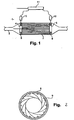
- Fig. 1 shows a purification device that can be, for example, a catalytic converter 2 that is located on the exhaust line 3 of an internal combustion engine (not shown).
- the catalytic converter 2 has (i) an inlet port 4 through which untreated exhaust gas can flow in and (ii) an outlet port 5 through which treated exhaust gas can be released into the atmosphere.
- the catalytic converter 2 reduces the toxicity of the exhaust gas emitted by an internal combustion engine.
- the catalytic converter 2 has to operate at high temperatures so that the oxidation/reduction reaction can effectively reduce undesirable emissions of pollutants.
- the invention makes provision for an arrangement 1 that can, in effect, contain the thermal energy that is stored in the catalytic converter 2.
- the arrangement 1 includes thermal containment means that are located at each end of the catalytic converter 2.
- the inlet port 4 and the outlet port 5 are both concerned with the arrangement 1 according to the invention.
- Fig. 2 shows a further embodiment of the thermal containment means.
- a circular frame 8 can be provided at one or at both ends of the catalytic converter 2.
- the circular frame 8 supports a series of rotatable blades 9 arranged in an iris diaphragm fashion that can close off partially or entirely the catalytic converter inlet and outlet ports 4 and 5.
- the rotatable blades 9 can be made of a metallic core covered by a ceramic coating so as to provide significant insulating capability.
- Each insulated rotatable blade 9 can be driven by actuating means that can be comprised of a pneumatic, electric or hydraulic actuator 10. Via, for example, a vehicle CAN bus, the actuator 10 can be controlled by a vehicle controller 11 that, for example, includes a CPU, a RAM and a ROM.
- each thermal energy containing rotatable blade 9 can have a transversal motion with respect to the flow of exhaust gas.
- each thermal energy containing rotatable blade 9 can move between a retracted position and a thermal containing position wherein the said blade transversally covers the inlet port or the outlet port of the catalytic converter 2 and contains the thermal energy that can be stored in the catalytic converter 2 from an earlier engine operation.
- the arrangement of the invention makes it possible to shut off both ends of the catalytic converter.
- the thermal energy containing rotatable blades 9 move into the thermal containing position as soon as the internal combustion engine is turned off.
- the thermal energy containing plates 9 move into the retracted position and allow the flow of exhaust gas to enter the catalytic converter.
- the catalytic converter 2 can resume operation without the usual phase of warming up where the catalytic converter does not operate efficiently.
- the arrangement according to the invention makes it possible to adapt the section of the catalytic converter that can be used to treat exhaust gas.
- the catalytic converter When the engine starts operation, the catalytic converter cannot instantaneously reach a required operational temperature which allows an efficient treatment of the exhaust gas.
- the arrangement of the invention makes it possible to restrict the inlet port and outlet port of the catalytic converter.
- the flow of exhaust gas can be focused on a restricted section of the catalytic converter which can quickly reach the required operational temperature.
- the thermal containment means can then be fully retracted when the temperature in the catalytic converter reaches the required efficiency.
- the thermal energy containment means can be a throttle, a diaphragm, a shutter or any other shutting system.
Landscapes
- Engineering & Computer Science (AREA)
- Chemical & Material Sciences (AREA)
- Chemical Kinetics & Catalysis (AREA)
- Combustion & Propulsion (AREA)
- Mechanical Engineering (AREA)
- General Engineering & Computer Science (AREA)
- Health & Medical Sciences (AREA)
- Toxicology (AREA)
- Exhaust Gas After Treatment (AREA)
Claims (8)
- Wärmeenergie enthaltende Einrichtung (1) für eine Abgasreinigungsvorrichtung, die in einer Abgasleitung (3) eines Verbrennungsmotors untergebracht ist, wobei die Reinigungsvorrichtung einen Einlasskanal (4), durch den Abgas von dem Verbrennungsmotor einströmen kann, und einen Auslasskanal (5) aufweist, durch den das behandelte Abgas ausströmen kann, wobei die Einrichtung eine zurückziehbare stromaufwärtige Wärmeenergie enthaltende Einrichtung, die stromaufwärts der Reinigungsvorrichtung angeordnet ist, und eine zurückziehbare stromabwärtige Wärmeenergie enthaltende Einrichtung, die stromabwärts der Reinigungsvorrichtung angeordnet ist, und eine Betätigungseinrichtung zur Steuerung der Position der stromaufwärtigen Wärmeenergie enthaltenden Einrichtung und der stromabwärtigen Wärmeenergie enthaltenden Einrichtung bezüglich des Einlasskanals (4) bzw. des Auslasskanals (5) der Reinigungsvorrichtung umfasst, wobei die stromaufwärtige Wärmeenergie enthaltende Einrichtung und die stromabwärtige Wärmeenergie enthaltende Einrichtung zwischen (i) einer Motorbetriebsposition, in der sich die stromaufwärtige Wärmeenergie enthaltende Einrichtung und die stromabwärtige Wärmeenergie enthaltende Einrichtung in einer wenigstens teilweise zurückgezogenen Position befinden und die Strömung von Abgas in die und aus der Abgasreinigungsvorrichtung ermöglichen, und (ii) einer Wärmeenergieerhaltungsposition bewegbar sind, in der wenigstens eine der stromaufwärtigen Wärmeenergie enthaltenden Einrichtung und der stromabwärtigen Wärmeenergie enthaltenden Einrichtung den Einlasskanal bzw. den Auslasskanal der Reinigungsvorrichtung absperren,
dadurch gekennzeichnet, dass die Einrichtung es ermöglicht, den Einlass- und Auslasskanal des Katalysators so zu verengen, dass die Strömung von Abgasen auf einen begrenzten Abschnitt des Katalysators fokussiert werden kann. - Einrichtung nach Anspruch 1, dadurch gekennzeichnet, dass eine der stromaufwärtigen Wärmeenergie enthaltenden Einrichtung und der stromabwärtigen Wärmeenergie enthaltenden Einrichtung einen kreisförmigen Rahmen (8) aufweist, der eine Reihe von drehbaren Flügeln (9) trägt, die in Art einer Irismembrane angeordnet sind und den Einlass- und den Auslasskanal der Reinigungsvorrichtung wenigstens teilweise schließen können.
- Einrichtung nach Anspruch 2, dadurch gekennzeichnet, dass der die drehbaren Flügel (9) tragende Rahmen (8) in den Einlass- oder Auslasskanal (4, 5) eingreift.
- Einrichtung nach einem der Ansprüche 1 bis 3, dadurch gekennzeichnet, dass eine der stromaufwärtigen Wärmeenergie enthaltenden Einrichtung und der stromabwärtigen Wärmeenergie enthaltenden Einrichtung eine Drehplatte aufweist, die eine Reihe von Öffnungen wachsenden Durchmessers und wenigstens einen massiven Sektor mit einer Fläche aufweist, die wenigstens gleich dem Querschnitt der Abgasreinigungsvorrichtung ist, wobei die Drehplatte im Winkel zwischen (i) einer Motorbetriebsposition, in der eine der Öffnungen mit dem Einlass- oder dem Auslasskanal übereinstimmt, und (ii) einer Wärmeenergieerhaltungsposition positioniert wird, in der der wenigstens eine massive Sektor den Einlass- oder den Auslasskanal der Reinigungsvorrichtung abdeckt.
- Einrichtung nach einem der Ansprüche 1 bis 4, dadurch gekennzeichnet, dass eine der stromaufwärtigen Wärmeenergie enthaltenden Einrichtung und der stromabwärtigen Wärmeenergie enthaltenden Einrichtung eine massive Platte mit einer Fläche aufweist, die wenigstens gleich dem Querschnitt der Abgasreinigungsvorrichtung ist, wobei die massive Platte in Querrichtung zwischen zwischen (i) einer Motorbetriebsposition, in der sich die massive Platte in einer zurückgezogenen Position befindet und den Einlass- oder den Auslasskanal wenigstens teilweise öffnet, und (ii) einer Wärmeenergieerhaltungsposition bewegbar ist, in der die massive Platte den Einlass- oder den Auslasskanal der Reinigungsvorrichtung abdeckt.
- Einrichtung nach einem der Ansprüche 1 bis 5, dadurch gekennzeichnet, dass die Wärmeenergie enthaltenden Einrichtungen einen Metallkern umfassen, der mit einer Keramikschicht beschichtet ist.
- Einrichtung nach einem der Ansprüche 1 bis 6, dadurch gekennzeichnet, dass die Abgasreinigungsvorrichtung einen Katalysator umfasst.
- Einrichtung nach einem der Ansprüche 1 bis 7, dadurch gekennzeichnet, dass die Abgasreinigungsvorrichtung einen Dieselpartikelfilter umfasst.
Applications Claiming Priority (1)
| Application Number | Priority Date | Filing Date | Title |
|---|---|---|---|
| PCT/IB2007/004441 WO2009081231A1 (en) | 2007-12-21 | 2007-12-21 | Thermal energy containing arrangement for an exhaust gas purification device |
Publications (2)
| Publication Number | Publication Date |
|---|---|
| EP2235335A1 EP2235335A1 (de) | 2010-10-06 |
| EP2235335B1 true EP2235335B1 (de) | 2011-09-21 |
Family
ID=39717600
Family Applications (1)
| Application Number | Title | Priority Date | Filing Date |
|---|---|---|---|
| EP07870465A Active EP2235335B1 (de) | 2007-12-21 | 2007-12-21 | Wärmeenergie enthaltende anordnung für eine abgasreinigungsvorrichtung |
Country Status (5)
| Country | Link |
|---|---|
| US (1) | US20110146250A1 (de) |
| EP (1) | EP2235335B1 (de) |
| CN (1) | CN101903623B (de) |
| AT (1) | ATE525554T1 (de) |
| WO (1) | WO2009081231A1 (de) |
Families Citing this family (7)
| Publication number | Priority date | Publication date | Assignee | Title |
|---|---|---|---|---|
| DE102013204401B4 (de) * | 2013-03-13 | 2016-06-30 | Mtu Friedrichshafen Gmbh | System zur Abgasnachbehandlung, Verfahren und Brennkraftmaschine |
| DE102013204405A1 (de) * | 2013-03-13 | 2014-09-18 | Mtu Friedrichshafen Gmbh | System zur Abgasnachbehandlung für eine Brennkraftmaschine, Verfahren zur Beeinflussung einer Abgas-Zusammensetzung und Brennkraftmaschine |
| DE102014209952B4 (de) * | 2013-06-17 | 2018-07-19 | Ford Global Technologies, Llc | Abgasnachbehandlungsvorrichtung, sowie Verfahren zur Abgasnachbehandlung |
| DE102015102301A1 (de) * | 2015-02-18 | 2016-08-18 | Volkswagen Aktiengesellschaft | Abgasbehandlungsvorrichtung |
| EP3303848B1 (de) | 2015-06-05 | 2022-08-24 | MTD products Inc | Gebläse mit einlassverschluss |
| US10668900B2 (en) * | 2016-05-09 | 2020-06-02 | Washme Properties, Llc | Mechanism for selectively opening/closing a vehicle wash component inlet opening |
| US11326490B2 (en) * | 2018-05-02 | 2022-05-10 | Faurecia Emissions Control Technologies, Usa, Llc | Variable restriction valve for vehicle exhaust system |
Family Cites Families (16)
| Publication number | Priority date | Publication date | Assignee | Title |
|---|---|---|---|---|
| US2649272A (en) * | 1950-03-31 | 1953-08-18 | Robert C Barbato | Iris type valve construction |
| GB1395960A (en) * | 1971-09-13 | 1975-05-29 | Ford Motor Co | Catalytic converter |
| DE2321578A1 (de) * | 1973-04-28 | 1974-11-14 | Porsche Ag | Katalytisches abgas-reinigungsgeraet |
| US4094492A (en) * | 1977-01-18 | 1978-06-13 | The United States Of America As Represented By The United States Department Of Energy | Variable orifice using an iris shutter |
| EP0596854A1 (de) * | 1992-11-02 | 1994-05-11 | AVL Gesellschaft für Verbrennungskraftmaschinen und Messtechnik mbH.Prof.Dr.Dr.h.c. Hans List | Katalysator |
| JPH0949422A (ja) * | 1995-08-09 | 1997-02-18 | Denso Corp | 内燃機関の排出ガス浄化装置 |
| BE1012629A3 (nl) * | 1999-04-23 | 2001-01-09 | Stuvex Internat N V | Inrichting voor het afsluiten van leidingen. |
| JP3633401B2 (ja) * | 1999-10-26 | 2005-03-30 | トヨタ自動車株式会社 | 内燃機関の排気昇温装置 |
| JP2004100516A (ja) * | 2002-09-06 | 2004-04-02 | Mitsubishi Fuso Truck & Bus Corp | 内燃機関の故障検出装置 |
| US20040231323A1 (en) * | 2003-05-23 | 2004-11-25 | Fujita Mahoro M. | Exhaust system and process for operating the same |
| US7255012B2 (en) * | 2004-12-01 | 2007-08-14 | Rosemount Inc. | Process fluid flow device with variable orifice |
| JP2006274982A (ja) * | 2005-03-30 | 2006-10-12 | Mitsubishi Fuso Truck & Bus Corp | 排気浄化装置 |
| DE102005031068A1 (de) * | 2005-06-23 | 2006-12-28 | Deutsches Zentrum für Luft- und Raumfahrt e.V. | Katalysatorvorrichtung zur Gasreinigung und Verfahren zur Temperierung einer Katalysatorstruktur |
| US20090044517A1 (en) * | 2005-07-06 | 2009-02-19 | Takahiro Oba | Exhaust gas purification system for an internal combustion engine |
| US8549846B2 (en) * | 2006-03-24 | 2013-10-08 | GM Global Technology Operations LLC | Diesel particulate filter regeneration via resistive surface heating |
| US8215613B2 (en) * | 2008-06-06 | 2012-07-10 | Neil Cheung | Virtual variable valve intake and exhaust for the internal combustion engine |
-
2007
- 2007-12-21 US US12/747,908 patent/US20110146250A1/en not_active Abandoned
- 2007-12-21 WO PCT/IB2007/004441 patent/WO2009081231A1/en not_active Ceased
- 2007-12-21 EP EP07870465A patent/EP2235335B1/de active Active
- 2007-12-21 CN CN200780102034.XA patent/CN101903623B/zh active Active
- 2007-12-21 AT AT07870465T patent/ATE525554T1/de not_active IP Right Cessation
Also Published As
| Publication number | Publication date |
|---|---|
| WO2009081231A1 (en) | 2009-07-02 |
| EP2235335A1 (de) | 2010-10-06 |
| US20110146250A1 (en) | 2011-06-23 |
| CN101903623A (zh) | 2010-12-01 |
| CN101903623B (zh) | 2014-06-04 |
| ATE525554T1 (de) | 2011-10-15 |
Similar Documents
| Publication | Publication Date | Title |
|---|---|---|
| US10167795B2 (en) | Exhaust gas treatment system warm-up methods | |
| US20110146250A1 (en) | Thermal energy containing arrangement for an exhaust gas purification device | |
| JP5752797B2 (ja) | 排気ガス再循環機能を有する車両用内燃機関 | |
| RU2481478C2 (ru) | Способ и устройство для холодного пуска двигателя внутреннего сгорания | |
| EP2732141B1 (de) | Verfahren und vorrichtung zur reaktivierung von abgasreinigungssystemen von dieselmotoren mit niederdruck-agr | |
| US7640731B2 (en) | Method for controlling exhaust gas flow and temperature through regenerable exhaust gas treatment devices | |
| JP5859638B2 (ja) | 自動車用ディーゼルエンジンの運転方法 | |
| US9574482B2 (en) | Method for operating components for exhaust gas after-treatment and exhaust gas after-treatment apparatus | |
| JPH02196120A (ja) | 内燃機関の排気微粒子処理装置 | |
| CN101405486A (zh) | 具有由可控阻隔装置来变化过滤表面的柴油机废气过滤的方法和设备 | |
| CN103850763A (zh) | 一种汽车排气再净化系统及其净化方法 | |
| JP2002510004A (ja) | 上流のウォータートラップを備える加熱可能触媒コンバータ装置 | |
| EP3354873B1 (de) | System zur verringerung des schadstoffausstosses eines verbrennungsmotors | |
| JP2004162611A (ja) | 内燃機関の排気浄化装置 | |
| US11867107B2 (en) | Internal combustion engine for a motor vehicle and motor vehicle | |
| JP4083478B2 (ja) | 内燃機関 | |
| WO2013105221A1 (ja) | 内燃機関の排気浄化装置 | |
| CN111089009A (zh) | 具有排气后处理的内燃发动机和用于操作这种内燃发动机的方法 | |
| JP2006242175A (ja) | Pm連続再生装置およびpm連続再生方法 | |
| WO2015046506A1 (ja) | 排気ガス浄化システム及び排気ガス浄化方法 | |
| US12264610B1 (en) | Cold start catalyst bypass system | |
| JP2005069238A (ja) | エンジンの排出ガス浄化システム | |
| JPH04353211A (ja) | 内燃機関用フィルタ再生装置 | |
| KR102375164B1 (ko) | 터보 컴파운드 시스템 제어방법 | |
| JPH04353209A (ja) | 内燃機関用フィルタ再生装置 |
Legal Events
| Date | Code | Title | Description |
|---|---|---|---|
| PUAI | Public reference made under article 153(3) epc to a published international application that has entered the european phase |
Free format text: ORIGINAL CODE: 0009012 |
|
| 17P | Request for examination filed |
Effective date: 20100721 |
|
| AK | Designated contracting states |
Kind code of ref document: A1 Designated state(s): AT BE BG CH CY CZ DE DK EE ES FI FR GB GR HU IE IS IT LI LT LU LV MC MT NL PL PT RO SE SI SK TR |
|
| AX | Request for extension of the european patent |
Extension state: AL BA HR MK RS |
|
| REG | Reference to a national code |
Ref country code: DE Ref legal event code: R079 Ref document number: 602007017438 Country of ref document: DE Free format text: PREVIOUS MAIN CLASS: F01N0003021000 Ipc: F01N0013140000 |
|
| GRAP | Despatch of communication of intention to grant a patent |
Free format text: ORIGINAL CODE: EPIDOSNIGR1 |
|
| RIC1 | Information provided on ipc code assigned before grant |
Ipc: F01N 13/14 20100101AFI20110209BHEP |
|
| DAX | Request for extension of the european patent (deleted) | ||
| GRAS | Grant fee paid |
Free format text: ORIGINAL CODE: EPIDOSNIGR3 |
|
| GRAA | (expected) grant |
Free format text: ORIGINAL CODE: 0009210 |
|
| AK | Designated contracting states |
Kind code of ref document: B1 Designated state(s): AT BE BG CH CY CZ DE DK EE ES FI FR GB GR HU IE IS IT LI LT LU LV MC MT NL PL PT RO SE SI SK TR |
|
| REG | Reference to a national code |
Ref country code: GB Ref legal event code: FG4D |
|
| REG | Reference to a national code |
Ref country code: CH Ref legal event code: EP |
|
| REG | Reference to a national code |
Ref country code: IE Ref legal event code: FG4D |
|
| REG | Reference to a national code |
Ref country code: DE Ref legal event code: R096 Ref document number: 602007017438 Country of ref document: DE Effective date: 20111117 |
|
| REG | Reference to a national code |
Ref country code: NL Ref legal event code: VDEP Effective date: 20110921 |
|
| PG25 | Lapsed in a contracting state [announced via postgrant information from national office to epo] |
Ref country code: LT Free format text: LAPSE BECAUSE OF FAILURE TO SUBMIT A TRANSLATION OF THE DESCRIPTION OR TO PAY THE FEE WITHIN THE PRESCRIBED TIME-LIMIT Effective date: 20110921 Ref country code: SE Free format text: LAPSE BECAUSE OF FAILURE TO SUBMIT A TRANSLATION OF THE DESCRIPTION OR TO PAY THE FEE WITHIN THE PRESCRIBED TIME-LIMIT Effective date: 20110921 Ref country code: FI Free format text: LAPSE BECAUSE OF FAILURE TO SUBMIT A TRANSLATION OF THE DESCRIPTION OR TO PAY THE FEE WITHIN THE PRESCRIBED TIME-LIMIT Effective date: 20110921 |
|
| LTIE | Lt: invalidation of european patent or patent extension |
Effective date: 20110921 |
|
| PG25 | Lapsed in a contracting state [announced via postgrant information from national office to epo] |
Ref country code: GR Free format text: LAPSE BECAUSE OF FAILURE TO SUBMIT A TRANSLATION OF THE DESCRIPTION OR TO PAY THE FEE WITHIN THE PRESCRIBED TIME-LIMIT Effective date: 20111222 Ref country code: CY Free format text: LAPSE BECAUSE OF FAILURE TO SUBMIT A TRANSLATION OF THE DESCRIPTION OR TO PAY THE FEE WITHIN THE PRESCRIBED TIME-LIMIT Effective date: 20110921 Ref country code: AT Free format text: LAPSE BECAUSE OF FAILURE TO SUBMIT A TRANSLATION OF THE DESCRIPTION OR TO PAY THE FEE WITHIN THE PRESCRIBED TIME-LIMIT Effective date: 20110921 Ref country code: SI Free format text: LAPSE BECAUSE OF FAILURE TO SUBMIT A TRANSLATION OF THE DESCRIPTION OR TO PAY THE FEE WITHIN THE PRESCRIBED TIME-LIMIT Effective date: 20110921 Ref country code: LV Free format text: LAPSE BECAUSE OF FAILURE TO SUBMIT A TRANSLATION OF THE DESCRIPTION OR TO PAY THE FEE WITHIN THE PRESCRIBED TIME-LIMIT Effective date: 20110921 |
|
| REG | Reference to a national code |
Ref country code: AT Ref legal event code: MK05 Ref document number: 525554 Country of ref document: AT Kind code of ref document: T Effective date: 20110921 |
|
| PG25 | Lapsed in a contracting state [announced via postgrant information from national office to epo] |
Ref country code: BE Free format text: LAPSE BECAUSE OF FAILURE TO SUBMIT A TRANSLATION OF THE DESCRIPTION OR TO PAY THE FEE WITHIN THE PRESCRIBED TIME-LIMIT Effective date: 20110921 |
|
| PG25 | Lapsed in a contracting state [announced via postgrant information from national office to epo] |
Ref country code: IS Free format text: LAPSE BECAUSE OF FAILURE TO SUBMIT A TRANSLATION OF THE DESCRIPTION OR TO PAY THE FEE WITHIN THE PRESCRIBED TIME-LIMIT Effective date: 20120121 Ref country code: CZ Free format text: LAPSE BECAUSE OF FAILURE TO SUBMIT A TRANSLATION OF THE DESCRIPTION OR TO PAY THE FEE WITHIN THE PRESCRIBED TIME-LIMIT Effective date: 20110921 Ref country code: SK Free format text: LAPSE BECAUSE OF FAILURE TO SUBMIT A TRANSLATION OF THE DESCRIPTION OR TO PAY THE FEE WITHIN THE PRESCRIBED TIME-LIMIT Effective date: 20110921 |
|
| PG25 | Lapsed in a contracting state [announced via postgrant information from national office to epo] |
Ref country code: NL Free format text: LAPSE BECAUSE OF FAILURE TO SUBMIT A TRANSLATION OF THE DESCRIPTION OR TO PAY THE FEE WITHIN THE PRESCRIBED TIME-LIMIT Effective date: 20110921 Ref country code: PT Free format text: LAPSE BECAUSE OF FAILURE TO SUBMIT A TRANSLATION OF THE DESCRIPTION OR TO PAY THE FEE WITHIN THE PRESCRIBED TIME-LIMIT Effective date: 20120123 Ref country code: PL Free format text: LAPSE BECAUSE OF FAILURE TO SUBMIT A TRANSLATION OF THE DESCRIPTION OR TO PAY THE FEE WITHIN THE PRESCRIBED TIME-LIMIT Effective date: 20110921 Ref country code: IT Free format text: LAPSE BECAUSE OF FAILURE TO SUBMIT A TRANSLATION OF THE DESCRIPTION OR TO PAY THE FEE WITHIN THE PRESCRIBED TIME-LIMIT Effective date: 20110921 Ref country code: EE Free format text: LAPSE BECAUSE OF FAILURE TO SUBMIT A TRANSLATION OF THE DESCRIPTION OR TO PAY THE FEE WITHIN THE PRESCRIBED TIME-LIMIT Effective date: 20110921 Ref country code: RO Free format text: LAPSE BECAUSE OF FAILURE TO SUBMIT A TRANSLATION OF THE DESCRIPTION OR TO PAY THE FEE WITHIN THE PRESCRIBED TIME-LIMIT Effective date: 20110921 |
|
| PLBE | No opposition filed within time limit |
Free format text: ORIGINAL CODE: 0009261 |
|
| STAA | Information on the status of an ep patent application or granted ep patent |
Free format text: STATUS: NO OPPOSITION FILED WITHIN TIME LIMIT |
|
| PG25 | Lapsed in a contracting state [announced via postgrant information from national office to epo] |
Ref country code: DK Free format text: LAPSE BECAUSE OF FAILURE TO SUBMIT A TRANSLATION OF THE DESCRIPTION OR TO PAY THE FEE WITHIN THE PRESCRIBED TIME-LIMIT Effective date: 20110921 Ref country code: MC Free format text: LAPSE BECAUSE OF NON-PAYMENT OF DUE FEES Effective date: 20111231 |
|
| REG | Reference to a national code |
Ref country code: CH Ref legal event code: PL |
|
| 26N | No opposition filed |
Effective date: 20120622 |
|
| GBPC | Gb: european patent ceased through non-payment of renewal fee |
Effective date: 20111221 |
|
| REG | Reference to a national code |
Ref country code: FR Ref legal event code: ST Effective date: 20120831 |
|
| REG | Reference to a national code |
Ref country code: IE Ref legal event code: MM4A |
|
| REG | Reference to a national code |
Ref country code: DE Ref legal event code: R097 Ref document number: 602007017438 Country of ref document: DE Effective date: 20120622 |
|
| PG25 | Lapsed in a contracting state [announced via postgrant information from national office to epo] |
Ref country code: GB Free format text: LAPSE BECAUSE OF NON-PAYMENT OF DUE FEES Effective date: 20111221 Ref country code: LI Free format text: LAPSE BECAUSE OF NON-PAYMENT OF DUE FEES Effective date: 20111231 Ref country code: CH Free format text: LAPSE BECAUSE OF NON-PAYMENT OF DUE FEES Effective date: 20111231 Ref country code: IE Free format text: LAPSE BECAUSE OF NON-PAYMENT OF DUE FEES Effective date: 20111221 |
|
| PG25 | Lapsed in a contracting state [announced via postgrant information from national office to epo] |
Ref country code: MT Free format text: LAPSE BECAUSE OF FAILURE TO SUBMIT A TRANSLATION OF THE DESCRIPTION OR TO PAY THE FEE WITHIN THE PRESCRIBED TIME-LIMIT Effective date: 20110921 |
|
| PG25 | Lapsed in a contracting state [announced via postgrant information from national office to epo] |
Ref country code: FR Free format text: LAPSE BECAUSE OF NON-PAYMENT OF DUE FEES Effective date: 20120102 Ref country code: ES Free format text: LAPSE BECAUSE OF FAILURE TO SUBMIT A TRANSLATION OF THE DESCRIPTION OR TO PAY THE FEE WITHIN THE PRESCRIBED TIME-LIMIT Effective date: 20120101 |
|
| PG25 | Lapsed in a contracting state [announced via postgrant information from national office to epo] |
Ref country code: LU Free format text: LAPSE BECAUSE OF NON-PAYMENT OF DUE FEES Effective date: 20111221 |
|
| PG25 | Lapsed in a contracting state [announced via postgrant information from national office to epo] |
Ref country code: BG Free format text: LAPSE BECAUSE OF FAILURE TO SUBMIT A TRANSLATION OF THE DESCRIPTION OR TO PAY THE FEE WITHIN THE PRESCRIBED TIME-LIMIT Effective date: 20111221 |
|
| PG25 | Lapsed in a contracting state [announced via postgrant information from national office to epo] |
Ref country code: TR Free format text: LAPSE BECAUSE OF FAILURE TO SUBMIT A TRANSLATION OF THE DESCRIPTION OR TO PAY THE FEE WITHIN THE PRESCRIBED TIME-LIMIT Effective date: 20110921 |
|
| PG25 | Lapsed in a contracting state [announced via postgrant information from national office to epo] |
Ref country code: HU Free format text: LAPSE BECAUSE OF FAILURE TO SUBMIT A TRANSLATION OF THE DESCRIPTION OR TO PAY THE FEE WITHIN THE PRESCRIBED TIME-LIMIT Effective date: 20110921 |
|
| REG | Reference to a national code |
Ref country code: DE Ref legal event code: R082 Ref document number: 602007017438 Country of ref document: DE Representative=s name: V. FUENER EBBINGHAUS FINCK HANO, DE |
|
| REG | Reference to a national code |
Ref country code: DE Ref legal event code: R081 Ref document number: 602007017438 Country of ref document: DE Owner name: VOLVO TRUCK CORP., SE Free format text: FORMER OWNER: RENAULT TRUCKS, SAINT PRIEST, FR Effective date: 20141219 Ref country code: DE Ref legal event code: R082 Ref document number: 602007017438 Country of ref document: DE Representative=s name: V. FUENER EBBINGHAUS FINCK HANO, DE Effective date: 20141219 |
|
| PGFP | Annual fee paid to national office [announced via postgrant information from national office to epo] |
Ref country code: DE Payment date: 20241227 Year of fee payment: 18 |