EP2236404B1 - Vehicule du type à selle - Google Patents
Vehicule du type à selle Download PDFInfo
- Publication number
- EP2236404B1 EP2236404B1 EP10154247A EP10154247A EP2236404B1 EP 2236404 B1 EP2236404 B1 EP 2236404B1 EP 10154247 A EP10154247 A EP 10154247A EP 10154247 A EP10154247 A EP 10154247A EP 2236404 B1 EP2236404 B1 EP 2236404B1
- Authority
- EP
- European Patent Office
- Prior art keywords
- collar
- bolt
- engine
- range
- diameter portion
- Prior art date
- Legal status (The legal status is an assumption and is not a legal conclusion. Google has not performed a legal analysis and makes no representation as to the accuracy of the status listed.)
- Active
Links
Images





Classifications
-
- B—PERFORMING OPERATIONS; TRANSPORTING
- B62—LAND VEHICLES FOR TRAVELLING OTHERWISE THAN ON RAILS
- B62K—CYCLES; CYCLE FRAMES; CYCLE STEERING DEVICES; RIDER-OPERATED TERMINAL CONTROLS SPECIALLY ADAPTED FOR CYCLES; CYCLE AXLE SUSPENSIONS; CYCLE SIDECARS, FORECARS, OR THE LIKE
- B62K11/00—Motorcycles, engine-assisted cycles or motor scooters with one or two wheels
- B62K11/02—Frames
- B62K11/04—Frames characterised by the engine being between front and rear wheels
Definitions
- This invention relates to a saddle type vehicle according to the preamble of claim 1 or 7, and particularly to an improved technique for an engine fastening structure.
- a saddle type vehicle according to the preamble of claim 1 or 7 is known from US 2004/238254 A1 .
- a motorcycle wherein an engine having high weight is rigidly mounted through a collar travels on a road having a large gap, then the vehicle undergoes upward and downward vibrations, and a load higher than holding force of the contact seating faces at the opposite ends of the collar may be generated at the fastening portions and the fastening bolt may undergo shearing deformation and may be plastically deformed by a very small amount. If the fastening bolt is plastically deformed, then variation of the contacting portions of the frame, collar and engine and variation in contact pressure distribution of the seating faces occur. This sometimes results in failure in stabilized seating face contact and in variation of vibrations or the drivability. In such an instance, the structure of the fastening portion between the frame and the engine is set appropriately in accordance with the vehicle.
- a structure wherein, in an engine supporting structure for a motorcycle wherein a collar is interposed between a frame and an engine, a wedge-like projection is provided on the opposite end seating faces of the collar is disclosed.
- the present invention has been made in view of the situation described above, and the object of the present invention resides in provision of a saddle type vehicle which has an engine fastening structure which stabilizes seating face contact between a frame and a collar and between an engine and the collar and is low in cost and easy in fastening working.
- a saddle type vehicle which includes an engine supporting portion provided on a vehicle body frame, and an engine side female threaded portion, and a collar interposed between the engine supporting portion and the engine side female threaded portion, and wherein the engine supporting portion, collar and engine side female threaded portion are fastened by a bolt, is characterized in that between the collar and the bolt at least at a location opposing to a boundary between the collar and the engine supporting portion or another boundary between the collar and the engine side female threaded portion, a gap in a diametrical direction between said collar and said bolt greater than a gap at any other location between said collar and said bolt is provided.
- the saddle type vehicle is characterized in that, in addition to the configuration of the invention as set forth in claim 1, at least one of an engine side end portion and a frame side end portion of a fitting hole of the collar is formed as a great diameter portion having a great inner diameter, and any other portion of the fitting hole of the collar is formed as a small diameter portion having a smaller diameter than that of the great diameter portion.
- the saddle type vehicle is characterized in that, in addition to the configuration of the invention as set forth in claim 2, the collar great diameter portion has a width equal to or greater than 5 mm, and a diameter difference between the great diameter portion and the bolt is equal to or greater than 1 mm.
- the saddle type vehicle is characterized in that, in addition to the configuration of the invention as set forth in claim 3, a mark portion is provided on a cylindrical face of the great diameter portion side of the collar.
- the saddle type vehicle is characterized in that, in addition to the configuration of the invention as set forth in claim 1, one of a portion of the bolt within a range from the engine side end portion of the collar to the engine side female threaded portion, another portion of the bolt within another range from the engine supporting portion to the frame side end portion of the collar and a portion of the bolt within a further range of an intermediate portion of the collar is formed as a great diameter portion, that where the portion of the bolt within the range from the engine side end portion of the collar to the engine side female threaded portion is formed as the great diameter portion, also an end portion of the bolt within a range of a portion of the engine supporting portion which is outside of the frame is formed as the great diameter portion, that where the portion of the bolt within the range from the engine supporting portion to the frame side end portion of the collar is formed as the great diameter portion, also an end portion of the bolt which is on the inner side of the engine side female threaded portion is formed as the great diameter portion, that where the portion of the bolt within
- the saddle type vehicle is characterized in that, in addition to the configuration of the invention as set forth in claim 5, the small diameter portion of the bolt has a width of 5 mm or more within the range of the collar from an end portion of the collar, and an inner diameter difference between the small diameter portion of the bolt and the fitting hole of the collar is 1 mm or more.
- a saddle type vehicle which includes a pair of left and right engine supporting portions provided on a vehicle body frame, an engine having a through-hole provided therein, a collar interposed between one of the engine supporting portions and the through-hole of the engine, and a penetrating bolt having a male threaded portion formed at an end portion thereof and extending through the pair of left and right engine supporting portions, the collar and the through-hole of the engine and a nut for being screwed with the male threaded end portion of the penetrating bolt to fasten the pair of left and right engine supporting portions, collar and engine, is characterized in that between the collar and the bolt at least at a location opposing to a boundary between the collar and the engine supporting portion or another boundary between the collar and the through-hole, a gap in a diametrical direction between said collar and said bolt greater than a gap at any other location between said collar and said bolt is provided.
- the saddle type vehicle is characterized in that, in addition to the configuration of the invention as set forth in claim 7, at least one of an engine side end portion and a frame side end portion of a fitting hole of the collar is formed as a great diameter portion having a great inner diameter, and any other portion of the fitting hole of the collar is formed as a small diameter portion having a smaller diameter than that of the great diameter portion.
- the saddle type vehicle is characterized in that, in addition to the configuration of the invention as set forth in claim 8, the collar great diameter portion has a width equal to or greater than 5 mm, and a diameter difference between the great diameter portion and the bolt is equal to or greater than 1 mm.
- the saddle type vehicle is characterized in that, in addition to the configuration of the invention as set forth in claim 9, a mark portion is provided on a cylindrical face of the great diameter portion side of the collar.
- the saddle type vehicle is characterized in that, in addition to the configuration of the invention as set forth in claim 7, one of a portion of the bolt within a range from the engine side end portion of the collar to the through-hole, another portion of the bolt within another range from the engine supporting portion to the frame side end portion of the collar and a portion of the bolt within a further range of an intermediate portion of the collar is formed as a great diameter portion, that where the portion of the bolt within the range from the engine side end portion of the collar to the through-hole is formed as the great diameter portion, also an end portion of the bolt within a range of a portion of the engine supporting portion which is outside of the frame is formed as the great diameter portion, that where the portion of the bolt within the range from the engine supporting portion to the frame side end portion of the collar is formed as the great diameter portion, also an end portion of the bolt which is on the inner side of the through-hole is formed as the great diameter portion, that where the portion of the bolt within the range of the intermediate portion of the collar is formed as
- the saddle type vehicle is characterized in that, in addition to the configuration of the invention as set forth in claim 11, the small diameter portion of the bolt has a width of 5 mm or more within the range of the collar from an end portion of the collar, and an inner diameter difference between the small diameter portion of the bolt and the fitting hole of the collar is 1 mm or more.
- the present invention is suitably applied, for example, to a motorcycle which is a saddle type vehicle.
- FIG. 1 is a side elevational view showing a basic configuration of a motorcycle according to the embodiment
- FIG. 2 is a side elevational view of the left side of a vehicle body.
- a vehicle body frame 11 of the motorcycle 1 includes a head pipe 15 for supporting a front fork 13 for steering operation, a pair of left and right main frames 17 extending rearwardly downwardly from the head pipe 15, a pair of left and right intermediate frames 19 connecting to rear ends of the main frames 17 and extending upwardly and downwardly, and a pair of left and right seat rails 21 extending rearwardly upwardly from upper portions of the intermediate frames 19.
- a front wheel 25 is supported for rotation at a lower end of the front fork 13, and a handle bar 27 is connected to an upper end of the front fork 13.
- a front fender 29 which covers over the front wheel 25 is supported on the front fork 13.
- Disk brakes 101 and 103 shown in FIG. 1 are attached to the front wheel 25 and a rear wheel 47, respectively.
- the disk brake 101 for the front wheel 25 has a brake disk 105 secured to the front wheel 25 for integrally rotating with the front wheel 25, and a caliper 107 attached to the front fork 13.
- the caliper 107 has a pair of built-in friction pads movable in directions toward and away from each other by pistons (not shown) by a hydraulic pressure generated from a master cylinder not shown.
- the friction pads sandwich braking faces 109 and 125 of the opposite side faces of the brake disks 105 and 111 to apply braking force to the front wheel 25 and the rear wheel 47, respectively.
- a V-type water-cooled 4-cylinder engine 31 is carried on the main frames 17 and the intermediate frames 19 such that it is supported by a first supporting portion 700A, a second supporting portion 700B, a third supporting portion 700C and a fourth supporting portion 700D shown in FIG. 2 .
- a front side cylinder exhaust pipe 35 extends forwardly from a front side cylinder 33 of the engine 31, and a rear side cylinder exhaust pipe 39 extends rearwardly once from a rear side cylinder 37 and then extends forwardly and further extends rearwardly again.
- the front side cylinder exhaust pipe 35 and the rear side cylinder exhaust pipe 39 extend downwardly along the front face of a crankcase 41 of the engine 31 and are positioned below the crankcase 41 with a catalyst chamber (CAT chamber) 32 interposed therebetween.
- CAT chamber catalyst chamber
- the catalyst chamber 43 connects to a rear collecting pipe 45 through a collecting pipe hereinafter described.
- the rear collecting pipe 45 is disposed in a space formed between a lower portion of the crankcase 41 and the rear wheel 47 and connects to a muffler 49 which extends to the vehicle body right side of the rear wheel 47.
- the rear collecting pipe 45 is supported below the crankcase 41.
- the muffler 49 is disposed in a crossing relationship with a swing arm 53, which supports the rear wheel 47 at a rear end portion thereof, as viewed in side elevation.
- the swing arm 53 is supported at a front end portion thereof for rocking motion in upward and downward directions at a lower portion of the muffler 49 and is suspended by a rear cushion 57 provided between the swing arm 53 and an upper end portion of the pivot plate 51.
- a step holder 407 including a rider's step 403 is provided between the front wheel 25 and the rear wheel 47.
- Output power of the engine 31 is transmitted to the rear wheel 47 through a drive shaft 59.
- the drive shaft 59 is built in the swing arm 53 disposed on the left side of the engine 31 in a state wherein it is directed in a forward direction Fr of the advancing direction of the motorcycle.
- a fuel tank 63 supported by the main frames 17 is disposed above the engine 31, and a rider's seat (main seat) 65 for allowing a rider to be seated thereon is disposed rearwardly of the fuel tank 63 such that it is supported by the seat rails 21.
- a pillion seat 67 as a passenger's seat for being seated by a passenger is disposed rearwardly of the rider's seat 65.
- a canister 201 is provided downwardly of a rear portion of the fuel tank 63, and the canister 201 catches volatile fuel gas in the fuel tank 63 without allowing the same to leak to the outside.
- reference numeral 210 denotes a lid, 212 a fuel filler, and 213 a purge pipe.
- a radiator 69 is disposed in front of the engine 31.
- the vehicle body frame 11 forwardly of the head pipe 15 is covered with a front cowl 71 made of synthetic resin. Further, a front portion of the main frames 17 and front portions and lower portions of the radiator 69 and the engine 31 are covered from the opposite sides thereof with a lower side cowl (not shown) made of synthetic resin and connecting to the front cowl 71.
- a rear cowl 73 for covering a rear portion of the vehicle body frame 11 and a rear fender 75 for covering the rear wheel 47 disposed below the rear cowl 73 from above are attached to a rear portion of the vehicle body frame 11. Further, a pair of left and right plate attaching portions 77 for attaching a license plate not shown are provided on the rear fender 75.
- a rear combination lamp 79 wherein a pair of left and right winkers 302 and a tail and stop lamp 304 between the left and right winkers 302 are integrated with each other is disposed such that a rear portion of the rear combination lamp 79 faces rearwardly from a rear end of the rear cowl 73.
- reference numeral 81 denotes a pillion step holder provided on the left and right of the vehicle body, and 83 a pillion step.
- an engine supporting portion is provided on the vehicle body frame 11, and a bolt is inserted in the engine supporting portion and a nut is tightened to the bolt to support the engine 31 on the engine supporting portion.
- a gap may be provided between the engine supporting portion and the engine 31, and in order to fill up the gap, a collar is interposed between the engine supporting portion and the engine 31.
- the engine 31 is supported on the vehicle body frame 11 by the first supporting portion 700A, second supporting portion 700B, third supporting portion 700C and fourth supporting portion 700D.
- FIG. 3 is a sectional view showing the first supporting portion and the second supporting portion for the engine
- FIG. 4 is a sectional view including the third supporting portion of the engine
- FIG. 5 is an enlarged view of part of FIG. 4
- FIG. 6 is a sectional view including the fourth supporting portion of the engine as viewed from the lower face side
- FIG. 7 is an enlarged view of part of FIG. 6 .
- the first supporting portion 700A includes left and right engine supporting portions 707a and 707b provided on the vehicle body frame 11, left and right engine side female threaded portions 703a and 703b provided on the engine 31, collars 705a and 705b interposed between the engine supporting portions 707a and 707b and the engine side female threaded portions 703a and 703b, and bolts 709a and 709b for fastening the left and right engine supporting portions 707a and 707b, collars 705a and 705b and left and right engine side female threaded portions 703a and 703b.
- the second supporting portion 700B includes left and right engine supporting portions 715a and 715b, left and right engine side female threaded portions 711 a and 711 b provided on the engine 31, collars 713a and 713b interposed between the engine supporting portions 715a and 715b and the engine side female threaded portions 711a and 711b, and bolts 717a and 717b for fastening the left and right engine supporting portions 715a and 715b, collars 713a and 713b and left and right engine side female threaded portions 711 a and 711 b.
- a collar with an expanding slot is used for the collar 713b.
- the third supporting portion 700C includes left and right engine supporting portions 725a and 725b disposed at a rear portion of the engine 31 and left and right engine side through-hole portions 721 a and 721 b fastened to the left and right engine supporting portions 725a and 725b.
- collars 723a and 723b are interposed between the left and right engine supporting portions 725a and 725b and the left and right engine side through-hole portions 721 a and 721 b provided on the engine 31 and between the engine supporting portions 725a and 725b and the engine side through-hole portions 721a and 721b.
- the left and right engine supporting portions 725a and 725b, collars 723a and 723b and engine side through-hole portions 721a and 721b are fastened by a through bolt 727 and a nut 729.
- a collar with an expanding slit is used for the collar 723b.
- the fourth supporting portion 700D includes left and right engine supporting portions 733a and 733b disposed at a rear portion of the engine 31 and left and right engine side through-hole portions 731a and 731b fastened to the left and right engine supporting portions 733a and 733b.
- left and right engine supporting portions 733a and 733b disposed at a rear portion of the engine 31 and left and right engine side through-hole portions 731a and 731b fastened to the left and right engine supporting portions 733a and 733b.
- the fourth supporting portion 700D includes the left and right engine supporting portions 733a and 733b, the left and right engine side through-hole portions 731a and 731b provided on the engine 31, a collar 735b interposed between the engine supporting portion 733b and the engine side through-hole portion 731 b, and a through bolt 737 and a nut 739 by which the engine supporting portions 733a and 733b, collar 735b and engine side through-hole portions 731a and 731 b are fastened.
- the collar in a motorcycle of the rigid mount type, where an engine and a vehicle body frame are fastened to each other with a collar interposed therebetween, the collar has a clearance of approximately 0.3 mm from a fastening bolt. Therefore, the collar is relatively displaceable by a very small amount with respect to the bolt. The relative displacement between the collar and the bolt is suppressed by friction between a frame side seating face and an engine side seating face which are acted upon by axial force of the fastening. In a motorcycle of the rigid mount type, this seating face contact is assured to suppress vibrations at the engine fastening sections in directions other than a set direction of the engine to carry out setting of the driving feeling and the controllability.
- the traveling behavior of the motorcycle 1 varies from the set behavior. Vibrations in directions other than the supposed direction at the fastening sections between the engine 31 and the vehicle body frame 11 which give rise to such a variation of the traveling behavior as described above can be prevented if the fastening of the engine 31 is carried out in accordance with the prescription.
- FIG. 8 is conceptive views illustrating a shearing deformation situation of a supporting structure in (a) to (c) according to a comparative example which does not form part of the invention, but represents background art which is useful for understanding the invention
- FIG. 9 is conceptive views illustrating a plastic deformation situation of the supporting structure in (a) and (b) according to a comparative example which does not form part of the invention, but represents background art which is useful for understanding the invention. It is to be noted that, in the conceptive views described below, the deformation amount and the distortion amount are illustrated in an exaggerated manner.
- the seating face contact between the collar 1 and the engine 31 or between the collar 1 and the vehicle body frame 11 sometimes varies such that the contact occurs at part of the seating face as shown in (a) and (b) of FIG. 9 . If the seating face contact varies in this manner, then vibrations or the steering performance may vary. In such an instance, the fastening structure is set appropriately in accordance with the vehicle.
- the prior art document discloses the structure wherein a wedge-like projection is provided on the opposite end seating faces of the collar 1 in an engine supporting structure for a motorcycle wherein the collar 1 is interposed between the vehicle body frame 11 and the engine 31.
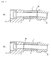
- FIG. 10 is a conceptive view illustrating a supporting situation of a stepped collar supporting structure according to the embodiment of the present invention in (a) and (b).
- a gap 741 which is greater than that at any other location is provided as shown in FIG. 10 . Consequently, concentration of shearing stress which acts upon the bolt 709a along a cross section which includes a collar end face 743 is moderated since the shearing stress is dispersed in the range in which the gap 741 is formed.
- a portion of an inner diameter D11 of at least one of an engine side end portion and a frame side end portion of a fitting hole 743 is formed as a large diameter portion, and any other portion of the fitting hole 743 is formed as a small diameter portion D12 having a diameter smaller than that of the large diameter portion D11. Consequently, positioning is carried out with the end face of the small diameter portion D12 which has a large contact area, and concentration of the shearing stress is moderated on the end face side of the large diameter portion D11 which has a small contact area.
- the large diameter portion D11 has a width W11 of 5 mm or more, and the diameter difference d11 between the large diameter portion D11 and the bolt 709a is equal to or greater than 1 mm. Particularly where the engine 31 has high weight, concentration of the shearing stress which appears where the width W (range) of the large diameter portion D11 is 5 mm or less and the diameter difference is 1 mm or less can be prevented.
- a mark-off line 745 which is a mark portion is provided on a cylindrical face of a portion of the collar 705a on the large diameter portion D11 side. This facilitates decision between the large diameter portion D11 side and the small diameter portion D12 side of the collar 705a.
- the mark portion in the present invention includes also a projection, a hollow and so forth.
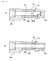
- FIG. 11 is conceptive views illustrating modifications to the stepped collar in (a) and (b).
- the large diameter portion D11 may be formed on an end side of a collar 750aA which opposes to the boundary between the collar 750aA and the engine supporting portion 707a. Further, the large diameter portion D11 may otherwise be formed on the opposite sides of the collar 750aA which oppose to the boundary between the collar 750aA and the engine supporting portion 707a and the boundary between the collar 750aA and the engine side female threaded portion 703a as shown in (b) of FIG. 11 .
- the gap 741 may otherwise be provided by varying the outer diameter of the bolt 709.
- FIG. 12 is conceptive views illustrating a supporting situation of a stepped bolt supporting structure according to the embodiment in (a) and (b), and
- FIG. 13 is conceptive views illustrating modifications to the stepped bolt in (a) and (b).
- one of a portion of a bolt 709 within a range from an engine side end portion of a collar 705 to the engine side female threaded portion 703a, another portion of the bolt 709 within another range from the engine supporting portion 707a to a frame side end portion of the collar 705 and a further portion of the bolt 709 within a range of an intermediate portion of the collar is formed as a large diameter portion D13.
- the portion of the bolt 709 within the range from the engine side end portion of the collar 705 to the engine side female threaded portion 703a is formed as the large diameter portion D13
- an end portion of the engine supporting portion 707a outside the frame is formed as the large diameter portion D13 ((b) of FIG. 13 ).
- the portion of the bolt 709 within the range from the engine supporting portion to the frame side end portion of the collar 705 is formed as the large diameter portion D13
- an inner side end portion of the engine side female threaded portion is formed as the large diameter portion D13
- the portion of the bolt 709A within the range of the intermediate portion of the collar 705 is formed as the large diameter portion D13 ((a) of FIG. 13 )
- an end portion of the engine supporting portion outside the frame and an inner side end portion of the engine side female threaded portion 703a are formed as the large diameter portion D13.
- any other portion of the bolt 709 than those mentioned above is formed as a small diameter portion D14 having a diameter smaller than that of the large diameter portion D13.
- the small diameter portion D14 of the bolt 709 has a width W12 of 5 mm or more within the collar at least from the collar end portion, and the inner diameter difference d12 between the small diameter portion D14 of the bolt 709 and the collar fitting hole 743 is 1 mm or more.
- concentration of the shearing stress which occurs where the width (range) of the small diameter portion D14 is 5 mm or less and the diameter difference between the small diameter portion D14 and the collar 705 is 1 mm or less is avoided, and an optimum bolt shape by which shearing deformation is suppressed is obtained.
- the fitting hole 743 of the collar 705a has a step formed thereon, where the frame 11, collar 705a and engine 31 tend to make relative displacement, positioning is carried out by the small diameter portion D12 and the bolt 709a.
- the area of the end face on the large diameter portion D11 side is small, relative displacement occurs on the seating face on the large diameter portion D11 side.
- the side on which relative displacement occurs between the collar 705a and the frame 11 or between the collar 705a and the engine 31 can be controlled. Since the bolt 709a on the large diameter portion D11 side is less likely to contact with the collar 705a, shearing deformation of the bolt 709a can be suppressed to the utmost. As a result, plastic deformation becomes less likely to occur with the bolt 709a, and the seating face contact at the opposite ends of the collar can be stabilized.
- the large diameter portion D11 side of the collar 705a is visually observed, and working upon fastening is facilitated.
- the bolt 709 since the bolt 709 has a step formed thereon, where the frame 11, collar 705 and engine 31 tend to make relative displacement, since positioning is carried out by the large diameter portion D13 and the collar 705, relative displacement occurs on the seating face on the small diameter portion D14 side. Accordingly, the side on which relative displacement occurs between the collar 705 and the frame 11 or between the collar 705 and the engine 31 can be controlled. Besides, since the bolt 709 on the small diameter portion D14 side is less likely to contact with the collar 705, shearing deformation of the bolt 709 can be suppressed to the utmost. As a result, shearing deformation becomes less likely to occur with the bolt 709, and the seating face contact at the opposite ends of the collar can be stabilized.
- the invention is directed to provide a saddle type vehicle which has an engine fastening structure which stabilizes seating face contact between a frame and a collar and between an engine and the collar and is low in cost and easy in fastening working.
- a saddle type vehicle which includes an engine supporting portion 707a provided on a vehicle body frame, and an engine side female threaded portion 703a, and a collar 705a interposed between the engine supporting portion 707a and the engine side female threaded portion 703a, and wherein the engine supporting portion 707a, collar 705a and engine side female threaded portion 703a are fastened by a bolt 709a, at least at locations between the collar 705a and the bolt 709a which oppose to a boundary between the collar 705a and the engine supporting portion 707a and another boundary between the collar 705a and the engine side female threaded portion 703a, a gap 741 greater than that at any other location is provided.
Landscapes
- Engineering & Computer Science (AREA)
- Mechanical Engineering (AREA)
- Automatic Cycles, And Cycles In General (AREA)
Claims (12)
- Véhicule de type à selle (1) qui comprend
une portion de support de moteur (707a, 707b) disposée sur une ossature de caisse (11) du véhicule, et
une portion filetée femelle côté moteur (703a, 703b), et
un collier (705a, 705b) interposé entre ladite portion de support de moteur (707a, 707b) et ladite portion filetée femelle côté moteur (703a, 703b), et dans lequel
ladite portion de support de moteur (707a, 707b), ledit collier (705a, 705b) et ladite portion filetée femelle côté moteur (703a, 703b) sont fixés par un boulon (709a, 709b),
caractérisé en ce que
à un emplacement entre ledit collier (705a, 705b) et ledit boulon (709a, 709b) opposé à une frontière entre ledit collier (705a, 705b) et ladite portion de support de moteur (707a, 707b) et/ou à un emplacement entre ledit collier (705a, 705b) et ledit boulon (709a, 709b) opposé à une frontière entre ledit collier (705a, 705b) et ladite portion filetée femelle côté moteur (703a, 703b), un écartement (741) dans une direction diamétrale entre ledit collier (705a, 705b) et ledit boulon (709a, 709b) plus grand qu'un écartement à un autre emplacement entre ledit collier (705a, 705b) et ledit boulon (709a, 709b) est agencé et s'étend axialement vers ledit écartement audit autre emplacement. - Véhicule de type à selle (1) selon la revendication 1, caractérisé en ce que
au moins l'une d'une portion d'extrémité côté moteur et d'une portion d'extrémité côté ossature d'un trou d'ajustement (743) dudit collier (705a, 705b) est formée comme une portion de grand diamètre ayant un grand diamètre interne (D11), et
toute autre portion du trou d'ajustement (743) dudit collier (705a, 705b) est formée en tant que portion de petit diamètre (D12) ayant un diamètre plus petit que celui de la portion de grand diamètre (D11). - Véhicule de type à selle (1) selon la revendication 2, caractérisé en ce que
ladite portion de grand diamètre de collier (D11) a une largeur (W11) supérieure ou égale à 5 mm, et
une différence de diamètre (d11) entre la portion de grand diamètre (D11) et ledit boulon (709a, 709b) est supérieure ou égale à 1 mm. - Véhicule de type à selle (1) selon la revendication 3, caractérisé en ce que
une portion de repère (745) est disposée sur une face cylindrique du côté de portion de grand diamètre (D11) dudit collier (705a, 705b). - Véhicule de type à selle (1) selon la revendication 1, caractérisé en ce que
l'une d'une portion dudit boulon (709) dans une plage allant de la portion d'extrémité côté moteur dudit collier (705) à la portion filetée femelle côté moteur (703a, 703b), une autre portion dudit boulon (709) dans une autre plage allant de ladite portion de support de moteur (707a, 707b) à la portion d'extrémité côté ossature dudit collier (705) et une portion dudit boulon (709) dans une plage supplémentaire d'une portion intermédiaire dudit collier (705) est formée en tant que portion de grand diamètre (D13), en ce que
où la portion dudit boulon (709) dans la plage allant de la portion d'extrémité côté moteur dudit collier (705) à la portion filetée femelle côté moteur (703a, 703b) est formée comme la portion de grand diamètre (D13), également une portion d'extrémité dudit boulon (709) dans une plage d'une portion de ladite portion de support de moteur (707a, 707b) qui est à l'extérieur de ladite ossature est formée comme la portion de grand diamètre (D13), en ce que
où la portion dudit boulon (709) dans la plage allant de ladite portion de support de moteur (707a, 707b) à la portion d'extrémité côté ossature dudit collier (705) est formée comme la portion de grand diamètre (D13), également une portion d'extrémité dudit boulon (709) qui est sur le côté interne de la portion filetée femelle côté moteur (703a, 703b) est formée comme la portion de grand diamètre (D13), en ce que
où la portion dudit boulon (709) dans la plage de la portion intermédiaire dudit collier (705) est formée comme la portion de grand diamètre (D13), également une portion dudit boulon (709) dans une plage d'une portion d'extrémité de ladite portion de support de moteur (707a, 707b) qui est à l'extérieur de ladite ossature et une portion dudit boulon (709) dans une autre plage d'une portion d'extrémité côté interne de ladite portion filetée femelle côté moteur (703a, 703b) sont formées comme les portions de grand diamètre (D13), et en ce que
toute autre portion dudit boulon (709) est formée comme une portion de petit diamètre (D14) ayant un diamètre plus petit que le diamètre de la ou des portion(s) de grand diamètre (D13). - Véhicule de type à selle (1) selon la revendication 5, caractérisé en ce que
la portion de petit diamètre (D14) dudit boulon (709) a une largeur de 5 mm ou plus dans la plage dudit collier (705) depuis une portion d'extrémité dudit collier (705), et
une différence de diamètre interne (d12) entre la portion de petit diamètre (D14) dudit boulon (709) et dudit trou d'ajustement (743) dudit collier (705) est de 1 mm ou plus. - Véhicule de type à selle (1) qui comprend
une paire de portions de support de moteur droite et gauche (725a, 725b) disposées sur une ossature de caisse de véhicule (11),
un moteur (31) ayant un trou traversant disposé à l'intérieur,
un collier (723a) interposé entre l'une (725a) desdites portions de support de moteur (725a, 725b) et le trou traversant dudit moteur (31), et
un boulon pénétrant (727) ayant une portion filetée mâle formée à une de ses portions d'extrémité et s'étendant à travers ladite paire de portions de support de moteur droite et gauche (725a, 725b), ledit collier (723a) et le trou traversant dudit moteur (31) et un écrou (729) destiné à être vissé avec la portion d'extrémité filetée mâle dudit boulon pénétrant (727) pour fixer ladite paire de portions de support de moteur droite et gauche (725a, 725b), le collier (723a ; 735b) et le moteur (31),
caractérisé en ce que
à un emplacement entre ledit collier (723a) et ledit boulon (727) opposé à une frontière entre ledit collier (723a) et ladite portion de support de moteur (725a) et/ou à un emplacement entre ledit collier (723a) et ledit boulon (727) opposé à une frontière entre ledit collier (723a) et ledit trou traversant, un écartement dans une direction diamétrale entre ledit collier (723a) et ledit boulon (727) plus grand qu'un écartement à un autre emplacement entre ledit collier (723a) et ledit boulon (727) est agencé et s'étend axialement vers ledit écartement audit autre emplacement. - Véhicule de type à selle (1) selon la revendication 7, caractérisé en ce que
au moins l'une d'une portion d'extrémité côté moteur et d'une portion d'extrémité côté ossature d'un trou d'ajustement dudit collier (723a) est formée comme une portion de grand diamètre ayant un grand diamètre interne, et
toute autre portion du trou d'ajustement dudit collier (723a) est formée comme une portion de petit diamètre ayant un plus petit diamètre que celui de la portion de grand diamètre. - Véhicule de type à selle (1) selon la revendication 8, caractérisé en ce que
ladite portion de grand diamètre de collier a une largeur supérieure ou égale à 5 mm, et
une différence de diamètre entre la portion de grand diamètre et ledit boulon (727) est supérieure ou égale à 1 mm. - Véhicule de type à selle (1) selon la revendication 9, caractérisé en ce que
une portion de repère est disposée sur une face cylindrique dudit côté de portion de grand diamètre dudit collier (723a). - Véhicule de type à selle (1) selon la revendication 7, caractérisé en ce que
l'une d'une portion dudit boulon (727) dans une plage allant de la portion d'extrémité côté moteur dudit collier (723a) au trou traversant, une autre portion dudit boulon (727) dans une autre plage allant de ladite portion de support de moteur à la portion d'extrémité côté ossature dudit collier (723a) et une portion dudit boulon (727) dans une plage supplémentaire d'une portion intermédiaire dudit collier (723a) est formée comme une portion de grand diamètre, en ce que
où la portion dudit boulon (727) dans la plage de la portion d'extrémité côté moteur dudit collier (723a) au trou traversant est formée comme la portion de grand diamètre, également une portion d'extrémité dudit boulon (727) dans une plage d'une portion de ladite portion de support de moteur qui est à l'extérieur de ladite ossature est formée comme la portion de grand diamètre, en ce que
où la portion dudit boulon (727) dans la plage allant de ladite portion de support de moteur à la portion d'extrémité côté ossature dudit collier (723a) est formée comme la portion de grand diamètre, également une portion d'extrémité dudit boulon (727) qui est sur le côté interne du trou traversant est formée comme la portion de grand diamètre, en ce que
où la portion dudit boulon (727) dans la plage de la portion intermédiaire dudit collier (723a) est formée comme la portion de grand diamètre, également une portion dudit boulon (727) dans une plage d'une portion d'extrémité de ladite portion de support de moteur qui est à l'extérieur de ladite ossature et une portion dudit boulon (727) dans une autre plage d'une portion d'extrémité côté interne dudit trou traversant sont formées comme les portions de grand diamètre, et en ce que
toute autre portion dudit boulon (727) est formée comme une portion de petit diamètre ayant un diamètre plus petit que le diamètre de la ou des portion (s) de grand diamètre. - Véhicule de type à selle (1) selon la revendication 11, caractérisé en ce que
la portion de petit diamètre dudit boulon (727) a une largeur de 5 mm ou plus dans la plage dudit collier (723a) depuis une portion d'extrémité dudit collier (723a), et
une différence de diamètre interne entre la portion de petit diamètre dudit boulon (727) et ledit trou d'ajustement dudit collier (723a) est de 1 mm ou plus.
Applications Claiming Priority (1)
| Application Number | Priority Date | Filing Date | Title |
|---|---|---|---|
| JP2009087781A JP5414331B2 (ja) | 2009-03-31 | 2009-03-31 | 鞍乗り型車両 |
Publications (2)
| Publication Number | Publication Date |
|---|---|
| EP2236404A1 EP2236404A1 (fr) | 2010-10-06 |
| EP2236404B1 true EP2236404B1 (fr) | 2012-07-11 |
Family
ID=41786475
Family Applications (1)
| Application Number | Title | Priority Date | Filing Date |
|---|---|---|---|
| EP10154247A Active EP2236404B1 (fr) | 2009-03-31 | 2010-02-22 | Vehicule du type à selle |
Country Status (3)
| Country | Link |
|---|---|
| US (1) | US8381863B2 (fr) |
| EP (1) | EP2236404B1 (fr) |
| JP (1) | JP5414331B2 (fr) |
Families Citing this family (7)
| Publication number | Priority date | Publication date | Assignee | Title |
|---|---|---|---|---|
| WO2010038586A1 (fr) * | 2008-09-30 | 2010-04-08 | 本田技研工業株式会社 | Structure de suspension moteur pour véhicule à moteur à deux roues |
| JP6029407B2 (ja) * | 2012-09-28 | 2016-11-24 | 川崎重工業株式会社 | 鞍乗型車両 |
| JP6244240B2 (ja) * | 2014-03-26 | 2017-12-06 | 本田技研工業株式会社 | 鞍乗型車両 |
| US10036465B2 (en) | 2015-07-17 | 2018-07-31 | Shimano Inc. | Bicycle component |
| US10940910B2 (en) | 2017-08-04 | 2021-03-09 | Shimano Inc. | Bicycle component and mounting structure for bicycle component |
| JP6921718B2 (ja) * | 2017-08-04 | 2021-08-18 | 株式会社シマノ | 自転車用コンポーネントおよび自転車用コンポーネントの取付構造 |
| JP7191911B2 (ja) * | 2020-09-25 | 2022-12-19 | 本田技研工業株式会社 | 車両 |
Family Cites Families (20)
| Publication number | Priority date | Publication date | Assignee | Title |
|---|---|---|---|---|
| AU539919B2 (en) * | 1980-09-22 | 1984-10-25 | Honda Giken Kogyo Kabushiki Kaisha | Motorcycle frame |
| JPS6230005U (fr) * | 1985-08-08 | 1987-02-23 | ||
| JPS62105896U (fr) * | 1985-12-25 | 1987-07-06 | ||
| JPH0162996U (fr) * | 1987-10-16 | 1989-04-21 | ||
| JPH0168999U (fr) * | 1987-10-26 | 1989-05-08 | ||
| JPH01195196A (ja) * | 1988-01-29 | 1989-08-07 | Suzuki Motor Co Ltd | 鞍乗型車両のエンジン懸架装置 |
| JPH01249586A (ja) * | 1988-03-31 | 1989-10-04 | Suzuki Motor Co Ltd | 車両のエンジン懸架装置 |
| JP2726451B2 (ja) * | 1988-10-20 | 1998-03-11 | ヤマハ発動機株式会社 | 自動二輪車のエンジン懸架構造 |
| JPH0331081A (ja) * | 1989-06-28 | 1991-02-08 | Yamaha Motor Co Ltd | 車両のエンジン懸架装置 |
| JPH04365688A (ja) * | 1991-06-13 | 1992-12-17 | Yamaha Motor Co Ltd | 自動二輪車のエンジン支持構造 |
| JPH10236376A (ja) * | 1997-02-27 | 1998-09-08 | Honda Motor Co Ltd | 自動二輪車のエンジン懸架装置 |
| US6315072B1 (en) * | 1999-07-29 | 2001-11-13 | Harley-Davidson Motor Company Group, Inc. | Motorcycle engine mounting assembly |
| JP4105442B2 (ja) * | 2002-01-31 | 2008-06-25 | 本田技研工業株式会社 | 自動二輪車のエンジンマウント構造 |
| BR0307753A (pt) * | 2002-02-20 | 2004-12-07 | Yamaha Motor Co Ltd | Dispositivo de jogo de engrenagens de válvula do motor |
| JP4217091B2 (ja) * | 2003-03-25 | 2009-01-28 | 本田技研工業株式会社 | エンジン冷却用ウォータポンプ |
| JP4236176B2 (ja) * | 2003-05-30 | 2009-03-11 | 本田技研工業株式会社 | 自動二輪車のエンジン支持構造 |
| US7469689B1 (en) * | 2004-09-09 | 2008-12-30 | Jones Daniel W | Fluid cooled supercharger |
| JP4627226B2 (ja) * | 2005-07-12 | 2011-02-09 | 本田技研工業株式会社 | 自動2輪車の車体構造 |
| US7690467B2 (en) * | 2007-07-02 | 2010-04-06 | Buell Motorcycle Company | Motorcycle frame with fuel-storage and break-away engine mounts |
| JP5162302B2 (ja) * | 2008-03-31 | 2013-03-13 | 本田技研工業株式会社 | 自動二輪車の車体フレーム |
-
2009
- 2009-03-31 JP JP2009087781A patent/JP5414331B2/ja not_active Expired - Fee Related
-
2010
- 2010-02-22 EP EP10154247A patent/EP2236404B1/fr active Active
- 2010-03-05 US US12/718,686 patent/US8381863B2/en not_active Expired - Fee Related
Also Published As
| Publication number | Publication date |
|---|---|
| EP2236404A1 (fr) | 2010-10-06 |
| US8381863B2 (en) | 2013-02-26 |
| US20100243364A1 (en) | 2010-09-30 |
| JP5414331B2 (ja) | 2014-02-12 |
| JP2010235058A (ja) | 2010-10-21 |
Similar Documents
| Publication | Publication Date | Title |
|---|---|---|
| EP2236404A1 (fr) | Vehicule du type à selle | |
| JP5478307B2 (ja) | 鞍乗り型車両の制動装置 | |
| JP4306442B2 (ja) | アンチロックブレーキ装置付自動二輪車 | |
| US7661502B2 (en) | Parking brake system | |
| JP6459859B2 (ja) | センサの支持構造及び自動二輪車 | |
| US20080079310A1 (en) | Brake system for motorcycle | |
| KR20100034689A (ko) | 자동이륜차 | |
| US20090242304A1 (en) | Motorcycle with control unit for controlling operation of a brake pressure regulating unit | |
| US11345430B2 (en) | Front fork lower portion structure of saddle riding vehicle | |
| EP2404796B1 (fr) | Motocyclette | |
| US10933934B2 (en) | Saddle-type vehicle | |
| JP2010195283A (ja) | 鞍乗り型車両 | |
| JP5098103B2 (ja) | 鞍乗り型車両のヘッドライト支持構造 | |
| JP2017013730A (ja) | Absユニットの取付構造及び自動二輪車 | |
| EP2048051B1 (fr) | Véhicule de type à enfourcher | |
| JP4607745B2 (ja) | 自動二輪車のエンジン支持構造 | |
| US20050247505A1 (en) | Frame and bracket system for motorized vehicle | |
| US20190023345A1 (en) | Straddle-type vehicle | |
| JP7579216B2 (ja) | 補助ブレーキを備えた鞍乗型車両 | |
| JP3157690U (ja) | 鞍乗型車両 | |
| JP6610699B2 (ja) | 慣性センサの取付構造及び鞍乗型車両 | |
| JP2010235055A (ja) | 鞍乗り型車両 | |
| CN112776929B (zh) | 车辆摆臂 | |
| JP6743863B2 (ja) | センサの支持構造 | |
| WO2025094200A1 (fr) | Véhicule |
Legal Events
| Date | Code | Title | Description |
|---|---|---|---|
| PUAI | Public reference made under article 153(3) epc to a published international application that has entered the european phase |
Free format text: ORIGINAL CODE: 0009012 |
|
| 17P | Request for examination filed |
Effective date: 20100222 |
|
| AK | Designated contracting states |
Kind code of ref document: A1 Designated state(s): AT BE BG CH CY CZ DE DK EE ES FI FR GB GR HR HU IE IS IT LI LT LU LV MC MK MT NL NO PL PT RO SE SI SK SM TR |
|
| RIC1 | Information provided on ipc code assigned before grant |
Ipc: B62M 7/02 20060101ALI20111213BHEP Ipc: B62K 11/04 20060101AFI20111213BHEP Ipc: B60K 5/12 20060101ALI20111213BHEP |
|
| GRAP | Despatch of communication of intention to grant a patent |
Free format text: ORIGINAL CODE: EPIDOSNIGR1 |
|
| GRAS | Grant fee paid |
Free format text: ORIGINAL CODE: EPIDOSNIGR3 |
|
| GRAA | (expected) grant |
Free format text: ORIGINAL CODE: 0009210 |
|
| AK | Designated contracting states |
Kind code of ref document: B1 Designated state(s): AT BE BG CH CY CZ DE DK EE ES FI FR GB GR HR HU IE IS IT LI LT LU LV MC MK MT NL NO PL PT RO SE SI SK SM TR |
|
| REG | Reference to a national code |
Ref country code: GB Ref legal event code: FG4D |
|
| RIN1 | Information on inventor provided before grant (corrected) |
Inventor name: KIKUCHI, OSAMU Inventor name: MORITA, KENJI Inventor name: HAYASHI, KANJI Inventor name: KIMISHIMA, TAKESHI Inventor name: HARIU, JUN Inventor name: AKIEDA, MASAO Inventor name: NAKANISHI, YUTAKA Inventor name: MORIMITSU, KAZUMA Inventor name: MUKAI, KATSUMASA |
|
| REG | Reference to a national code |
Ref country code: CH Ref legal event code: EP |
|
| REG | Reference to a national code |
Ref country code: AT Ref legal event code: REF Ref document number: 565955 Country of ref document: AT Kind code of ref document: T Effective date: 20120715 |
|
| REG | Reference to a national code |
Ref country code: IE Ref legal event code: FG4D |
|
| REG | Reference to a national code |
Ref country code: DE Ref legal event code: R096 Ref document number: 602010002133 Country of ref document: DE Effective date: 20120906 |
|
| REG | Reference to a national code |
Ref country code: NL Ref legal event code: VDEP Effective date: 20120711 |
|
| REG | Reference to a national code |
Ref country code: AT Ref legal event code: MK05 Ref document number: 565955 Country of ref document: AT Kind code of ref document: T Effective date: 20120711 |
|
| REG | Reference to a national code |
Ref country code: LT Ref legal event code: MG4D Effective date: 20120711 |
|
| PG25 | Lapsed in a contracting state [announced via postgrant information from national office to epo] |
Ref country code: CY Free format text: LAPSE BECAUSE OF FAILURE TO SUBMIT A TRANSLATION OF THE DESCRIPTION OR TO PAY THE FEE WITHIN THE PRESCRIBED TIME-LIMIT Effective date: 20120711 Ref country code: FI Free format text: LAPSE BECAUSE OF FAILURE TO SUBMIT A TRANSLATION OF THE DESCRIPTION OR TO PAY THE FEE WITHIN THE PRESCRIBED TIME-LIMIT Effective date: 20120711 Ref country code: IS Free format text: LAPSE BECAUSE OF FAILURE TO SUBMIT A TRANSLATION OF THE DESCRIPTION OR TO PAY THE FEE WITHIN THE PRESCRIBED TIME-LIMIT Effective date: 20121111 Ref country code: HR Free format text: LAPSE BECAUSE OF FAILURE TO SUBMIT A TRANSLATION OF THE DESCRIPTION OR TO PAY THE FEE WITHIN THE PRESCRIBED TIME-LIMIT Effective date: 20120711 Ref country code: BE Free format text: LAPSE BECAUSE OF FAILURE TO SUBMIT A TRANSLATION OF THE DESCRIPTION OR TO PAY THE FEE WITHIN THE PRESCRIBED TIME-LIMIT Effective date: 20120711 Ref country code: NO Free format text: LAPSE BECAUSE OF FAILURE TO SUBMIT A TRANSLATION OF THE DESCRIPTION OR TO PAY THE FEE WITHIN THE PRESCRIBED TIME-LIMIT Effective date: 20121011 Ref country code: LT Free format text: LAPSE BECAUSE OF FAILURE TO SUBMIT A TRANSLATION OF THE DESCRIPTION OR TO PAY THE FEE WITHIN THE PRESCRIBED TIME-LIMIT Effective date: 20120711 Ref country code: AT Free format text: LAPSE BECAUSE OF FAILURE TO SUBMIT A TRANSLATION OF THE DESCRIPTION OR TO PAY THE FEE WITHIN THE PRESCRIBED TIME-LIMIT Effective date: 20120711 |
|
| PG25 | Lapsed in a contracting state [announced via postgrant information from national office to epo] |
Ref country code: GR Free format text: LAPSE BECAUSE OF FAILURE TO SUBMIT A TRANSLATION OF THE DESCRIPTION OR TO PAY THE FEE WITHIN THE PRESCRIBED TIME-LIMIT Effective date: 20121012 Ref country code: SI Free format text: LAPSE BECAUSE OF FAILURE TO SUBMIT A TRANSLATION OF THE DESCRIPTION OR TO PAY THE FEE WITHIN THE PRESCRIBED TIME-LIMIT Effective date: 20120711 Ref country code: PT Free format text: LAPSE BECAUSE OF FAILURE TO SUBMIT A TRANSLATION OF THE DESCRIPTION OR TO PAY THE FEE WITHIN THE PRESCRIBED TIME-LIMIT Effective date: 20121112 Ref country code: PL Free format text: LAPSE BECAUSE OF FAILURE TO SUBMIT A TRANSLATION OF THE DESCRIPTION OR TO PAY THE FEE WITHIN THE PRESCRIBED TIME-LIMIT Effective date: 20120711 Ref country code: LV Free format text: LAPSE BECAUSE OF FAILURE TO SUBMIT A TRANSLATION OF THE DESCRIPTION OR TO PAY THE FEE WITHIN THE PRESCRIBED TIME-LIMIT Effective date: 20120711 Ref country code: SE Free format text: LAPSE BECAUSE OF FAILURE TO SUBMIT A TRANSLATION OF THE DESCRIPTION OR TO PAY THE FEE WITHIN THE PRESCRIBED TIME-LIMIT Effective date: 20120711 |
|
| PG25 | Lapsed in a contracting state [announced via postgrant information from national office to epo] |
Ref country code: NL Free format text: LAPSE BECAUSE OF FAILURE TO SUBMIT A TRANSLATION OF THE DESCRIPTION OR TO PAY THE FEE WITHIN THE PRESCRIBED TIME-LIMIT Effective date: 20120711 |
|
| PG25 | Lapsed in a contracting state [announced via postgrant information from national office to epo] |
Ref country code: DK Free format text: LAPSE BECAUSE OF FAILURE TO SUBMIT A TRANSLATION OF THE DESCRIPTION OR TO PAY THE FEE WITHIN THE PRESCRIBED TIME-LIMIT Effective date: 20120711 Ref country code: CZ Free format text: LAPSE BECAUSE OF FAILURE TO SUBMIT A TRANSLATION OF THE DESCRIPTION OR TO PAY THE FEE WITHIN THE PRESCRIBED TIME-LIMIT Effective date: 20120711 Ref country code: EE Free format text: LAPSE BECAUSE OF FAILURE TO SUBMIT A TRANSLATION OF THE DESCRIPTION OR TO PAY THE FEE WITHIN THE PRESCRIBED TIME-LIMIT Effective date: 20120711 Ref country code: RO Free format text: LAPSE BECAUSE OF FAILURE TO SUBMIT A TRANSLATION OF THE DESCRIPTION OR TO PAY THE FEE WITHIN THE PRESCRIBED TIME-LIMIT Effective date: 20120711 Ref country code: ES Free format text: LAPSE BECAUSE OF FAILURE TO SUBMIT A TRANSLATION OF THE DESCRIPTION OR TO PAY THE FEE WITHIN THE PRESCRIBED TIME-LIMIT Effective date: 20121022 |
|
| PLBE | No opposition filed within time limit |
Free format text: ORIGINAL CODE: 0009261 |
|
| STAA | Information on the status of an ep patent application or granted ep patent |
Free format text: STATUS: NO OPPOSITION FILED WITHIN TIME LIMIT |
|
| PG25 | Lapsed in a contracting state [announced via postgrant information from national office to epo] |
Ref country code: SK Free format text: LAPSE BECAUSE OF FAILURE TO SUBMIT A TRANSLATION OF THE DESCRIPTION OR TO PAY THE FEE WITHIN THE PRESCRIBED TIME-LIMIT Effective date: 20120711 |
|
| 26N | No opposition filed |
Effective date: 20130412 |
|
| PG25 | Lapsed in a contracting state [announced via postgrant information from national office to epo] |
Ref country code: BG Free format text: LAPSE BECAUSE OF FAILURE TO SUBMIT A TRANSLATION OF THE DESCRIPTION OR TO PAY THE FEE WITHIN THE PRESCRIBED TIME-LIMIT Effective date: 20121011 |
|
| REG | Reference to a national code |
Ref country code: DE Ref legal event code: R097 Ref document number: 602010002133 Country of ref document: DE Effective date: 20130412 |
|
| PG25 | Lapsed in a contracting state [announced via postgrant information from national office to epo] |
Ref country code: MC Free format text: LAPSE BECAUSE OF NON-PAYMENT OF DUE FEES Effective date: 20130228 |
|
| REG | Reference to a national code |
Ref country code: IE Ref legal event code: MM4A |
|
| PG25 | Lapsed in a contracting state [announced via postgrant information from national office to epo] |
Ref country code: IE Free format text: LAPSE BECAUSE OF NON-PAYMENT OF DUE FEES Effective date: 20130222 |
|
| PG25 | Lapsed in a contracting state [announced via postgrant information from national office to epo] |
Ref country code: MT Free format text: LAPSE BECAUSE OF FAILURE TO SUBMIT A TRANSLATION OF THE DESCRIPTION OR TO PAY THE FEE WITHIN THE PRESCRIBED TIME-LIMIT Effective date: 20120711 |
|
| REG | Reference to a national code |
Ref country code: CH Ref legal event code: PL |
|
| GBPC | Gb: european patent ceased through non-payment of renewal fee |
Effective date: 20140222 |
|
| PG25 | Lapsed in a contracting state [announced via postgrant information from national office to epo] |
Ref country code: LI Free format text: LAPSE BECAUSE OF NON-PAYMENT OF DUE FEES Effective date: 20140228 Ref country code: CH Free format text: LAPSE BECAUSE OF NON-PAYMENT OF DUE FEES Effective date: 20140228 |
|
| PG25 | Lapsed in a contracting state [announced via postgrant information from national office to epo] |
Ref country code: GB Free format text: LAPSE BECAUSE OF NON-PAYMENT OF DUE FEES Effective date: 20140222 |
|
| PG25 | Lapsed in a contracting state [announced via postgrant information from national office to epo] |
Ref country code: SM Free format text: LAPSE BECAUSE OF FAILURE TO SUBMIT A TRANSLATION OF THE DESCRIPTION OR TO PAY THE FEE WITHIN THE PRESCRIBED TIME-LIMIT Effective date: 20120711 |
|
| PG25 | Lapsed in a contracting state [announced via postgrant information from national office to epo] |
Ref country code: TR Free format text: LAPSE BECAUSE OF FAILURE TO SUBMIT A TRANSLATION OF THE DESCRIPTION OR TO PAY THE FEE WITHIN THE PRESCRIBED TIME-LIMIT Effective date: 20120711 |
|
| PG25 | Lapsed in a contracting state [announced via postgrant information from national office to epo] |
Ref country code: LU Free format text: LAPSE BECAUSE OF NON-PAYMENT OF DUE FEES Effective date: 20130222 Ref country code: HU Free format text: LAPSE BECAUSE OF FAILURE TO SUBMIT A TRANSLATION OF THE DESCRIPTION OR TO PAY THE FEE WITHIN THE PRESCRIBED TIME-LIMIT; INVALID AB INITIO Effective date: 20100222 Ref country code: MK Free format text: LAPSE BECAUSE OF FAILURE TO SUBMIT A TRANSLATION OF THE DESCRIPTION OR TO PAY THE FEE WITHIN THE PRESCRIBED TIME-LIMIT Effective date: 20120711 |
|
| REG | Reference to a national code |
Ref country code: FR Ref legal event code: PLFP Year of fee payment: 7 |
|
| REG | Reference to a national code |
Ref country code: FR Ref legal event code: PLFP Year of fee payment: 8 |
|
| REG | Reference to a national code |
Ref country code: FR Ref legal event code: PLFP Year of fee payment: 9 |
|
| PGFP | Annual fee paid to national office [announced via postgrant information from national office to epo] |
Ref country code: IT Payment date: 20180221 Year of fee payment: 9 Ref country code: FR Payment date: 20180111 Year of fee payment: 9 |
|
| REG | Reference to a national code |
Ref country code: DE Ref legal event code: R084 Ref document number: 602010002133 Country of ref document: DE |
|
| PG25 | Lapsed in a contracting state [announced via postgrant information from national office to epo] |
Ref country code: FR Free format text: LAPSE BECAUSE OF NON-PAYMENT OF DUE FEES Effective date: 20190228 Ref country code: IT Free format text: LAPSE BECAUSE OF NON-PAYMENT OF DUE FEES Effective date: 20190222 |
|
| PGFP | Annual fee paid to national office [announced via postgrant information from national office to epo] |
Ref country code: DE Payment date: 20260121 Year of fee payment: 17 |