EP2236760B1 - Thermisch entkoppeltes Übergangsstück einer Ringbrennkammer - Google Patents
Thermisch entkoppeltes Übergangsstück einer Ringbrennkammer Download PDFInfo
- Publication number
- EP2236760B1 EP2236760B1 EP10157028.1A EP10157028A EP2236760B1 EP 2236760 B1 EP2236760 B1 EP 2236760B1 EP 10157028 A EP10157028 A EP 10157028A EP 2236760 B1 EP2236760 B1 EP 2236760B1
- Authority
- EP
- European Patent Office
- Prior art keywords
- dilution
- transition piece
- heat shield
- wall
- shield member
- Prior art date
- Legal status (The legal status is an assumption and is not a legal conclusion. Google has not performed a legal analysis and makes no representation as to the accuracy of the status listed.)
- Not-in-force
Links
- 230000007704 transition Effects 0.000 title claims description 52
- 238000010790 dilution Methods 0.000 claims description 66
- 239000012895 dilution Substances 0.000 claims description 66
- 239000000567 combustion gas Substances 0.000 claims description 22
- 238000002485 combustion reaction Methods 0.000 claims description 19
- 238000001816 cooling Methods 0.000 claims description 19
- 239000007789 gas Substances 0.000 claims description 16
- 238000002347 injection Methods 0.000 claims description 10
- 239000007924 injection Substances 0.000 claims description 10
- 238000000034 method Methods 0.000 claims description 7
- 239000000112 cooling gas Substances 0.000 claims 2
- 230000003750 conditioning effect Effects 0.000 claims 1
- 238000005336 cracking Methods 0.000 description 4
- 239000000203 mixture Substances 0.000 description 4
- 239000000446 fuel Substances 0.000 description 3
- 230000004888 barrier function Effects 0.000 description 2
- 238000004891 communication Methods 0.000 description 2
- 150000001875 compounds Chemical class 0.000 description 2
- 230000037406 food intake Effects 0.000 description 2
- 238000012546 transfer Methods 0.000 description 2
- 229910000990 Ni alloy Inorganic materials 0.000 description 1
- 239000000919 ceramic Substances 0.000 description 1
- 238000010276 construction Methods 0.000 description 1
- 238000013461 design Methods 0.000 description 1
- 230000000694 effects Effects 0.000 description 1
- 230000002708 enhancing effect Effects 0.000 description 1
- 230000003116 impacting effect Effects 0.000 description 1
- 238000012423 maintenance Methods 0.000 description 1
- 239000012720 thermal barrier coating Substances 0.000 description 1
Images


Classifications
-
- F—MECHANICAL ENGINEERING; LIGHTING; HEATING; WEAPONS; BLASTING
- F01—MACHINES OR ENGINES IN GENERAL; ENGINE PLANTS IN GENERAL; STEAM ENGINES
- F01D—NON-POSITIVE DISPLACEMENT MACHINES OR ENGINES, e.g. STEAM TURBINES
- F01D9/00—Stators
- F01D9/02—Nozzles; Nozzle boxes; Stator blades; Guide conduits, e.g. individual nozzles
- F01D9/023—Transition ducts between combustor cans and first stage of the turbine in gas-turbine engines; their cooling or sealings
-
- F—MECHANICAL ENGINEERING; LIGHTING; HEATING; WEAPONS; BLASTING
- F05—INDEXING SCHEMES RELATING TO ENGINES OR PUMPS IN VARIOUS SUBCLASSES OF CLASSES F01-F04
- F05D—INDEXING SCHEME FOR ASPECTS RELATING TO NON-POSITIVE-DISPLACEMENT MACHINES OR ENGINES, GAS-TURBINES OR JET-PROPULSION PLANTS
- F05D2230/00—Manufacture
- F05D2230/60—Assembly methods
- F05D2230/64—Assembly methods using positioning or alignment devices for aligning or centring, e.g. pins
- F05D2230/642—Assembly methods using positioning or alignment devices for aligning or centring, e.g. pins using maintaining alignment while permitting differential dilatation
-
- F—MECHANICAL ENGINEERING; LIGHTING; HEATING; WEAPONS; BLASTING
- F05—INDEXING SCHEMES RELATING TO ENGINES OR PUMPS IN VARIOUS SUBCLASSES OF CLASSES F01-F04
- F05D—INDEXING SCHEME FOR ASPECTS RELATING TO NON-POSITIVE-DISPLACEMENT MACHINES OR ENGINES, GAS-TURBINES OR JET-PROPULSION PLANTS
- F05D2250/00—Geometry
- F05D2250/70—Shape
- F05D2250/75—Shape given by its similarity to a letter, e.g. T-shaped
-
- F—MECHANICAL ENGINEERING; LIGHTING; HEATING; WEAPONS; BLASTING
- F05—INDEXING SCHEMES RELATING TO ENGINES OR PUMPS IN VARIOUS SUBCLASSES OF CLASSES F01-F04
- F05D—INDEXING SCHEME FOR ASPECTS RELATING TO NON-POSITIVE-DISPLACEMENT MACHINES OR ENGINES, GAS-TURBINES OR JET-PROPULSION PLANTS
- F05D2260/00—Function
- F05D2260/20—Heat transfer, e.g. cooling
- F05D2260/201—Heat transfer, e.g. cooling by impingement of a fluid
-
- F—MECHANICAL ENGINEERING; LIGHTING; HEATING; WEAPONS; BLASTING
- F05—INDEXING SCHEMES RELATING TO ENGINES OR PUMPS IN VARIOUS SUBCLASSES OF CLASSES F01-F04
- F05D—INDEXING SCHEME FOR ASPECTS RELATING TO NON-POSITIVE-DISPLACEMENT MACHINES OR ENGINES, GAS-TURBINES OR JET-PROPULSION PLANTS
- F05D2260/00—Function
- F05D2260/20—Heat transfer, e.g. cooling
- F05D2260/202—Heat transfer, e.g. cooling by film cooling
-
- F—MECHANICAL ENGINEERING; LIGHTING; HEATING; WEAPONS; BLASTING
- F05—INDEXING SCHEMES RELATING TO ENGINES OR PUMPS IN VARIOUS SUBCLASSES OF CLASSES F01-F04
- F05D—INDEXING SCHEME FOR ASPECTS RELATING TO NON-POSITIVE-DISPLACEMENT MACHINES OR ENGINES, GAS-TURBINES OR JET-PROPULSION PLANTS
- F05D2260/00—Function
- F05D2260/20—Heat transfer, e.g. cooling
- F05D2260/205—Cooling fluid recirculation, i.e. after cooling one or more components is the cooling fluid recovered and used elsewhere for other purposes
-
- F—MECHANICAL ENGINEERING; LIGHTING; HEATING; WEAPONS; BLASTING
- F05—INDEXING SCHEMES RELATING TO ENGINES OR PUMPS IN VARIOUS SUBCLASSES OF CLASSES F01-F04
- F05D—INDEXING SCHEME FOR ASPECTS RELATING TO NON-POSITIVE-DISPLACEMENT MACHINES OR ENGINES, GAS-TURBINES OR JET-PROPULSION PLANTS
- F05D2260/00—Function
- F05D2260/30—Retaining components in desired mutual position
- F05D2260/31—Retaining bolts or nuts
-
- F—MECHANICAL ENGINEERING; LIGHTING; HEATING; WEAPONS; BLASTING
- F05—INDEXING SCHEMES RELATING TO ENGINES OR PUMPS IN VARIOUS SUBCLASSES OF CLASSES F01-F04
- F05D—INDEXING SCHEME FOR ASPECTS RELATING TO NON-POSITIVE-DISPLACEMENT MACHINES OR ENGINES, GAS-TURBINES OR JET-PROPULSION PLANTS
- F05D2260/00—Function
- F05D2260/30—Retaining components in desired mutual position
- F05D2260/36—Retaining components in desired mutual position by a form fit connection, e.g. by interlocking
Definitions
- the subject matter disclosed herein relates to the art of turbomachines and, more particularly, to a turbomachine including a thermally decoupled can-annular transition piece.
- gas turbine engines combust a fuel/air mixture that releases heat energy to form a high temperature gas stream.
- the high temperature gas stream is channeled to a turbine via a hot gas path.
- the turbine converts thermal energy from the high temperature gas stream to mechanical energy that rotates a turbine shaft.
- the turbine may be used in a variety of applications, such as for providing power to a pump or an electrical generator.
- turbomachines include an annular combustor within which are formed the combustion gases that create the high temperature gas stream.
- Other turbomachines employ a plurality of combustors arranged in a can-annular array. In such a turbomachine, the combustion gases are formed in each of the plurality of combustors and delivered to the turbine through a transition piece. In addition to providing a passage to the turbine, the transition piece provides an additional opportunity to enhance combustion.
- Certain turbomachines employ a series of dilution passages arranged in the transition piece. A portion of compressor air is passed along the transition piece, through the dilution passages, and into the combustion airstream. This portion of the compressor air, or dilution gases, is employed to enhance a profile/pattern factor of the combustion gases.
- JP S63 131924 is concerned with a cooling structure for a tail of a combustor.
- JP 2005 002899 is concerned with a gas turbine burner.
- JP 2003 065071 is concerned with a gas turbine combustor.
- US 4,719,748 is concerned with an impingement cooled transition duct.
- US 2008/276619 is concerned with impingement jets coupled to cooling channels for transition cooling.
- a turbomachine according to claim 1 is provided.
- a method of thermally decoupling a transition piece from combustion gases in a turbomachine according to claim 10 is provided.
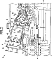
- Turbomachine 2 includes a compressor 4 and a combustor assembly 5 having at least one combustor 6 provided with an injection nozzle assembly housing 8.
- Turbomachine 2 also includes a turbine 10 and a common compressor/turbine shaft 12.
- the present invention is not limited to any one particular engine and may be used in connection with other turbomachines.
- combustor 6 is coupled in flow communication with compressor 4 and turbine 10.
- Compressor 4 includes a diffuser 22 and a compressor discharge plenum 24 that are coupled in flow communication with each other.
- Combustor 6 also includes an end cover 30 positioned at a first end thereof, and a cap member 34.
- Combustor 6 further includes a plurality of pre-mixers or injection nozzles, two of which are indicated at 37 and 38. Injection nozzles 37 and 38 are arranged about a central nozzle 39 forming a can-annular array 40. Although only three injection nozzles are shown, it should be understood that the number of injection nozzles employed in can annular array 40 can vary.
- combustor 6 includes a combustor casing 46 and a combustor liner 47. As shown, combustor liner 47 is positioned radially inward from combustor casing 46 so as to define a combustion chamber 48. An annular combustion chamber cooling passage 49 is defined between combustor casing 46 and combustor liner 47.
- Transition piece 55 channels combustion gases from combustion chamber 48 downstream towards a first stage turbine nozzle 62.
- transition piece 55 includes an inner wall 64 and an outer wall or impingement sleeve 65.
- Outer wall 65 includes a plurality of openings 66 that lead to an annular flow passage 68 defined between inner wall 64 and outer wall 65. With this arrangement, outer wall 65 controls cooling air flow (and heat exchange) via a pressure differential within annular flow passage 68.
- inner wall 64 includes a plurality of dilution orifices 67 that lead from annular flow passage 68 into a combustion flow passage 72 that extends between combustion chamber 48 and turbine 10.
- Flow passage 72 includes a compound curvature that is constructed to deliver the combustion gases to first turbine stage 62 in a manner that will be described more fully below.
- fuel is passed to injection nozzles 37-39 to mix with the compressed air to form a combustible mixture that passes from can-annular array 40 to combustion chamber 48 and ignited to form combustion gases.
- the combustion gases are then channeled to turbine 10 via transition piece 55. Thermal energy from the combustion gases is converted to mechanical rotational energy that is employed to drive compressor/turbine shaft 12.
- turbine 10 drives compressor 4 via compressor/turbine shaft 12 (shown in Figure 1 ).
- compressor 4 rotates, compressed air is discharged into diffuser 22 as indicated by associated arrows.
- a majority of the compressed air discharged from compressor 4 is channeled through compressor discharge plenum 24 towards combustor 6. Any remaining compressed air is channeled for use in cooling engine components.
- Compressed air within discharge plenum 24 is channeled into transition piece 55 via outer wall openings 66 and into annular flow passage 68. In configurations that do not employ an annular flow passage, the compressor discharge air passes through openings 66 without the pressure differential created by outer wall 65.
- a first or dilution portion of the compressed air is channeled from annular flow passage 68 through dilution orifices 67 into flow passage 72.
- a second portion of the compressed air is channeled through annular combustion chamber cooling passage 49 and to injection nozzles 37-39.
- the fuel and air are mixed to form the combustible mixture.
- the combustible mixture is ignited to form combustion gases within combustion chamber 48.
- Combustor casing 47 facilitates shielding combustion chamber 48 and its associated combustion processes from the outside environment such as, for example, surrounding turbine components.
- the combustion gases are channeled from combustion chamber 48 through guide cavity 72 and towards turbine nozzle 62.
- first stage turbine nozzle 62 creates a rotational force that ultimately produces work from turbomachine 2.
- transition piece 55 includes a plurality of heat shield members 80-85.
- heat shield member 80-85 includes similar structure, a detailed description will follow with reference to FIG. 3 in describing heat shield member 80 constructed in accordance with a first exemplary embodiment, with an understanding that heat shield members 81-85 are substantially similarly formed.
- heat shield member 80 includes a body 90 having a first surface 92 that extends to a second, opposing surface 94 through which extends a dilution passage 96.
- Body 90 is formed from, for example alloys of nickel or ceramics and shaped to conform to the compound curvature of transition piece 55.
- body 90 may include a thermal barrier coating applied to first surface 92 and/or second surface 94.
- Dilution passage 96 includes a first end section 97 that extends to a second end section 98.
- dilution passage 96 is off-set from dilution orifice 67 in order to encourage flow along second surface 94.
- heat shield member 80 is spaced from inner wall 64 of transition piece 55 so as to define a flow region 100. The particular dimensions of flow region 100 can vary depending upon design requirements.
- heat shield member 80 includes a plurality of surface enhancements or protuberances, one of which is indicated at 101, that extend outward from second surface 94. Protuberances 101 create turbulence within the dilution air passing through flow region 100.
- heat shield member 80 is mounted to yet spaced from inner wall 64 of transition piece 55.
- transition piece 55 includes a plurality of mounting members, two of which are indicated at 104 and 105 that project outward from inner wall 64.
- mounting members 104 and 105 take the form of hook members 108 and 109.
- Each hook member 108, 109 includes a corresponding first end section 111 and 112 as well, that extend to a second end section 114 and 115.
- heat shield member 80 includes a plurality of mounting elements, two of which are indicated at 120 and 121, that project outward from second surface 94.
- mounting elements 120 and 121 take the form of hook elements 124 and 125.
- Each hook element 124, 125 includes a corresponding first end 127 that extends to a respective second end 130 and 131 prior to terminating in a hook (not separately labeled).
- Hook elements 124 and 125 engage with hook members 108 and 109 to mount heat sealed member 80 to transition piece 55 so as to define flow passage 100.
- cooling air flowing through combustor flow passage 72 passes through dilution orifice 67 into flow region 100 to form dilution air.
- the dilution air passes along flow region 100 and through dilution passage 96 into combustor flow passage 72.
- heat shield member provides a thermal barrier to inner wall 64 of transition piece 55.
- the thermal barrier affords a level of protection to various portions of inner wall 64. For example, by decoupling inner wall 64 from the combustion gases in flow passage 72, cracking of inner wall 64, particularly in areas around dilution orifices 67, is mitigated. More specifically, hot gases ingested into a vena contracta formed with the dilution air mixes with the combustion gases leads to cracking of the inner wall 64 in areas adjacent dilution orifices 67. By providing an off set between dilution orifice 67 and dilution passage 96 ingestion of the hot gases is eliminated such that heat shield member 80 prolongs an overall operation lie of transition piece 55.
- heat shield member 134 includes a body 135 having a first surface 136 and an opposing, second surface 137.
- Heat shield member 134 includes a plurality of dilution passages 140-142 that extend through body 135.
- each dilution passage 140-142 is off-set from respective ones of dilution orifices 67 formed in inner wall 64 of transition piece 55.
- each dilution passage 140-142 is configured to enhance cooling of heat shield member 134.
- dilution passage 140 includes a first end section 144 that extends to a second end section 145 through an angled intermediate section 146. That is, first end section 144 is off-set from second end section 145 so as to increase an overall flow length of dilution passage 140. In this manner, that dilution air that forms an effusion flow passing through heat shield member 134 is provided with additional time to exchange heat, thereby enhancing thermal exchange.
- dilution passage 141 includes a first end section 151 that extends to a second end section 152 through an angled intermediate section 153 and dilution passage 142 includes a first end section 157 that extends to a second end section 158 through an angled intermediate section 159.
- each first end section 151 and 157 is off-set from corresponding ones of second end sections 152 and 158 so as to increase an overall flow length of dilution passages 141 and 142.
- heat shield member 134 includes first and second hook elements 164 and 165 that are configured to engage with hook members 108 and 109 on transition piece 55.
- heat shield member 170 constructed in accordance with yet another exemplary embodiment.
- heat shield member 170 includes a body 171 having a first surface 172 that extends toward an opposing, second surface 173.
- Heat shield member 170 includes a plurality of dilution passages 179-182 that extend between flow region 100 and combustor flow passage 72.
- each dilution passage 179-182 is configured to enhance heat transfer between cooling air passing through flow passage 100 towards combustor flow passage 72. That is, dilution passage 179 includes a first end section 185 that extends to a second end section 186 through an angled section 187.
- dilution passage 180 includes a first end section 190 that extends to a second end section 191 through an angled section 192
- dilution passage 181 includes a first end section 195 that extends to a second end section 196 through an angled section 197
- dilution passage 182 includes a first end section 200 that extends to a second end section through and angled intermediate section 202.
- each first end section 185, 190, 195 and 200 is off-set from corresponding ones of second end sections 186, 191, 196 and 207 so as to provide extended flow within body 171 to enhance heat transfer from heat shield member 170.
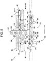
- heat shield member 170 is mounted to, yet spaced from inner wall 64 of transition piece 55 so as to define flow passage 100. More specifically, inner wall 64 includes a mounting member 209 shown in the form of an opening 211. Outer wall 65 also includes an opening (not separately labeled) that is in alignment with opening 211. Heat shield member 170 includes a mounting element 215 shown in the form of a projection or stud 218 that extends from second surface 173. Stud 218 is configured to extend through opening 211 so as to secure heat shield member 170 to transition piece 55.
- stud 218 includes a first end portion 226 that extends to a second end portion 227 and includes a threaded section 239 that is configured to receive a fastener 238.
- a second fastener 240 can be employed to provide a desired spacing from inner wall 64 so as to ensure alignment between adjacent heat shield members and provide uniformity to flow passage 100.
- the heat shield member is constructed in accordance with the exemplary embodiment to provide structure to reduce heat exposure to inner wall 64 of transition piece 55.
- cracking of inner wall 64, particularly in areas around dilution orifices 67 is mitigated.
- hot gases ingested into a vena contracta formed with the dilution air mixes with the combustion gases leads to cracking of the inner wall 64 in areas adjacent dilution orifices 67.
- heat shield member 80 prolongs an overall operation life of transition piece 55. That is, by providing a sacrificial component within transition piece 55, the heat shield members enhance serviceability and maintenance while extending an overall service life of turbomachine 2.
Landscapes
- Engineering & Computer Science (AREA)
- Mechanical Engineering (AREA)
- General Engineering & Computer Science (AREA)
- Turbine Rotor Nozzle Sealing (AREA)
Claims (14)
- Turbomaschine (2), umfassend:eine Brennkammerbaugruppe (5) einschließlich einer Vielzahl von Einspritzdüsen (37, 38), die angeordnet sind, um eine becherringförmige Anordnung (40) zu bilden;ein Übergangsstück (55) einschließlich einer Innenwand (64), die einen Verbrennungsströmungskanal (72) definiert;wobei das Übergangsstück (55) ferner Folgendes umfasst:eine Außenwand (65), wobei das Übergangsstück (55) einen ringförmigen Strömungskanal (68) zwischen der Innenwand (64) und der Außenwand (65) definiert;wobei die Außenwand (65) eine Vielzahl von Öffnungen (66) definiert, die zum ringförmigen Strömungskanal (68) führen;mindestens eine Verdünnungsöffnung (67), die in der Innenwand (64) des Übergangsstücks (55) gebildet ist, wobei die mindestens eine Verdünnungsöffnung (67) Verdünnungsgase zum Verbrennungsströmungskanal (72) führt;wobei die Turbomaschine (2) dadurch gekennzeichnet ist, dass sie ferner Folgendes umfasst:ein Hitzeschildelement (80), das an der Innenwand (64) des Übergangsstücks (55) im Verbrennungsströmungskanal (72) befestigt ist, wobei das Hitzeschildelement (80) einen Körper (135) einschließt, der eine erste Oberfläche (136) und eine gegenüberliegende zweite Oberfläche (137) aufweist, durch die sich mindestens ein Verdünnungskanal (140-142) erstreckt, wobei der mindestens eine Verdünnungskanal (140-142) von der mindestens einen Verdünnungsöffnung (67) versetzt ist, wobei das Hitzeschildelement (80) von der Innenwand (64) des Übergangsstücks (55) derart beabstandet ist, dass ein Strömungsbereich (100) zwischen der Innenwand (64) und der zweiten Oberfläche (137) definiert wird, wobei der Strömungsbereich (100) das Übergangsstück (55) von Verbrennungsgasen, die durch die becherringförmige Anordnung (40) von Einspritzdüsen erzeugt werden, thermisch entkoppelt;mindestens ein Befestigungselement (104), das am Übergangsstück (55) bereitgestellt ist; undmindestens ein Befestigungselement (120), das in der zweiten Oberfläche (137) des Hitzeschildelements (80) bereitgestellt ist, wobei das mindestens eine Befestigungselement (104) angepasst ist, um mit dem mindestens einen Befestigungselement (120) zu interagieren, damit das Hitzeschildelement (80) am Übergangsstück (55) befestigt wird.
- Turbomaschine (2) nach Anspruch 1, wobei das mindestens eine Befestigungselement (104) ein Hakenelement (108) umfasst, das sich von der Innenwand (64) des Übergangsstücks (55) zum Verbrennungsströmungskanal (72) nach außen erstreckt, und das mindestens eine Befestigungselement (120) ein Hakenelement (124) umfasst, das sich von der zweiten Oberfläche (137) des Hitzeschildelements (80) senkrecht nach außen erstreckt, wobei das Hakenelement (124) konfiguriert ist, um mit dem mindestens einen Hakenelement (108) zu koppeln, damit das Hitzeschildelement (80) an der Innenwand (64) des Übergangsstücks (55) befestigt wird.
- Turbomaschine (2) nach Anspruch 1, wobei das mindestens eine Befestigungselement (104) eine Öffnung (211) umfasst, die sich durch die Innenwand (64) des Übergangsstücks (55) erstreckt, und das mindestens eine Befestigungselement (120) einen Vorsprung (218) umfasst, der einen ersten Endabschnitt (226) aufweist, der sich von der zweiten Oberfläche (137) zu einem zweiten Endabschnitt (227) erstreckt, wobei der zweite Endabschnitt (227) angepasst ist, um sich durch die Öffnung (211) zu erstrecken, damit das Hitzeschildelement (80) am Übergangsstück (55) befestigt wird.
- Turbomaschine (2) nach Anspruch 3, ferner umfassend: ein Befestigungselement (238), das am zweiten Endabschnitt (227) des Vorsprungs (218) bereitgestellt ist.
- Turbomaschine (2) nach Anspruch 4, wobei der zweite Endabschnitt (227) des Vorsprungs (218) einen Gewindeabschnitt (233) einschließt.
- Turbomaschine (2) nach Anspruch 4, wobei das Befestigungselement (238) eine Mutter umfasst, die eine Vielzahl von Innengewinden aufweist, die derart konfiguriert sind, dass sie mit dem Gewindeabschnitt (233) des Vorsprungs (218) in Eingriff stehen.
- Turbomaschine (2) nach einem der vorhergehenden Ansprüche, wobei der Verdünnungskanal (140-142) einen ersten Endabschnitt (97) einschließt, der sich zu einem zweiten Endabschnitt erstreckt, wobei der erste Endabschnitt (97) vom zweiten Endabschnitt (98) versetzt ist.
- Turbomaschine (2) nach einem der vorhergehenden Ansprüche, wobei die mindestens eine Verdünnungsöffnung (67) eine Vielzahl von Verdünnungsöffnungen einschließt und der mindestens eine Verdünnungskanal (140-142) eine Vielzahl von Verdünnungskanälen (140-142) einschließt, wobei jeder der Vielzahl von Verdünnungskanälen (140-142) von jeder der Vielzahl von Verdünnungsöffnungen versetzt ist.
- Turbomaschine nach einem der vorhergehenden Ansprüche, wobei die zweite Oberfläche des Hitzeschildelements eine Vielzahl von Ausstülpungen einschließt, wobei die Vielzahl von Ausstülpungen einen Luftstrom, der durch den Strömungsbereich strömt, konditioniert.
- Verfahren zum thermischen Entkoppeln eines Übergangsstücks (55) von Verbrennungsgasen in einer Turbomaschine (2), wobei das Verfahren Folgendes umfasst:Erzeugen von Kühlgasen in einem Verdichterabschnitt der Turbomaschine (2);Leiten von Kühlgasen durch einen ringförmigen Kanal (68), der im Übergangsstück (55) zwischen einer Innenwand (64) und einer Außenwand (65) definiert ist, über eine Vielzahl von Öffnungen (66) in der Außenwand (65);Generieren von Verbrennungsgasen in einer Vielzahl von Brennkammern, die in einer becherringförmigen Anordnung (40) angeordnet sind;Führen der Verbrennungsgase in einen Strömungshohlraum der Turbomaschine (2), wobei der Strömungshohlraum die becherringförmige Anordnung (40) der Verbrennungskammern mit einer ersten Stufe einer Turbine fluidisch verbindet;Abschirmen einer Innenoberfläche des Übergangsstücks (55) von den Verbrennungsgasen mit mindestens einem Hitzeschildelement (80), wobei das mindestens eine Hitzeschildelement (80) von der Innenoberfläche des Übergangsstücks (55) beabstandet ist, um einen Strömungshohlraum zu bilden;Leiten des Kühlluftstroms durch mindestens eine Verdünnungsöffnung (67), die im Übergangsstück (55) gebildet ist, wobei die Verdünnungsöffnung (67) mit dem Strömungshohlraum fluidisch verbunden ist;Führen des Kühlluftstroms durch mindestens einen Verdünnungskanal (140-142), der im mindestens einen Hitzeschildelement (80) gebildet ist, wobei der mindestens eine Verdünnungskanal (140-142) von der mindestens einen Verdünnungsöffnung (67) versetzt ist, um einen Effusionsluftstrom zu schaffen, der über eine Oberfläche des mindestens einen Hitzeschildelements (80) strömt, um die Innenwand (64) des Übergangsstücks (55) von den Verbrennungsgasen thermisch zu entkoppeln.
- Verfahren nach Anspruch 10, wobei das Führen des Kühlluftstroms durch den mindestens einen Verdünnungskanal das Leiten des Kühlluftstroms in einen ersten Endabschnitt, der in einer ersten Oberfläche des Hitzeschildelements gebildet ist, zu einem zweiten Endabschnitt umfasst, wobei der zweite Endabschnitt vom ersten Endabschnitt versetzt ist.
- Verfahren nach Anspruch 10 oder 11, ferner umfassend: Führen des Kühlluftstroms über eine Vielzahl von Ausstülpungen, die auf dem Hitzeschildelement gebildet sind.
- Verfahren nach einem der Ansprüche 10 bis 12, wobei das Leiten des Kühlluftstroms durch mindestens eine Verdünnungsöffnung, die im Übergangsstück gebildet ist, das Leiten des Kühlluftstroms durch eine Vielzahl von Verdünnungsöffnungen, die im Übergangstück gebildet sind, umfasst.
- Verfahren nach Anspruch 13, wobei das Führen des Kühlluftstroms durch mindestens einen Verdünnungskanal, der im mindestens einen Hitzeschildelement gebildet ist, das Leiten des Kühlluftstroms durch eine Vielzahl von Verdünnungskanälen, die im Hitzeschildelement gebildet sind, umfasst, wobei jeder der Vielzahl von Verdünnungskanälen von den jeweiligen der Vielzahl von Verdünnungsöffnungen versetzt ist.
Applications Claiming Priority (1)
| Application Number | Priority Date | Filing Date | Title |
|---|---|---|---|
| US12/413,991 US8695322B2 (en) | 2009-03-30 | 2009-03-30 | Thermally decoupled can-annular transition piece |
Publications (3)
| Publication Number | Publication Date |
|---|---|
| EP2236760A2 EP2236760A2 (de) | 2010-10-06 |
| EP2236760A3 EP2236760A3 (de) | 2017-06-21 |
| EP2236760B1 true EP2236760B1 (de) | 2020-04-29 |
Family
ID=42226536
Family Applications (1)
| Application Number | Title | Priority Date | Filing Date |
|---|---|---|---|
| EP10157028.1A Not-in-force EP2236760B1 (de) | 2009-03-30 | 2010-03-19 | Thermisch entkoppeltes Übergangsstück einer Ringbrennkammer |
Country Status (4)
| Country | Link |
|---|---|
| US (1) | US8695322B2 (de) |
| EP (1) | EP2236760B1 (de) |
| JP (1) | JP5676126B2 (de) |
| CN (1) | CN101852132B (de) |
Families Citing this family (30)
| Publication number | Priority date | Publication date | Assignee | Title |
|---|---|---|---|---|
| US8245514B2 (en) * | 2008-07-10 | 2012-08-21 | United Technologies Corporation | Combustion liner for a gas turbine engine including heat transfer columns to increase cooling of a hula seal at the transition duct region |
| US8091365B2 (en) * | 2008-08-12 | 2012-01-10 | Siemens Energy, Inc. | Canted outlet for transition in a gas turbine engine |
| US9097117B2 (en) * | 2010-11-15 | 2015-08-04 | Siemens Energy, Inc | Turbine transition component formed from an air-cooled multi-layer outer panel for use in a gas turbine engine |
| US9133721B2 (en) * | 2010-11-15 | 2015-09-15 | Siemens Energy, Inc. | Turbine transition component formed from a two section, air-cooled multi-layer outer panel for use in a gas turbine engine |
| US20130086917A1 (en) * | 2011-10-06 | 2013-04-11 | Ilya Aleksandrovich Slobodyanskiy | Apparatus for head end direct air injection with enhanced mixing capabilities |
| US20130180252A1 (en) * | 2012-01-18 | 2013-07-18 | General Electric Company | Combustor assembly with impingement sleeve holes and turbulators |
| US9506359B2 (en) * | 2012-04-03 | 2016-11-29 | General Electric Company | Transition nozzle combustion system |
| US9217335B2 (en) * | 2012-05-09 | 2015-12-22 | General Electric Company | Fixture and method for adjusting workpiece |
| US9239165B2 (en) | 2012-06-07 | 2016-01-19 | United Technologies Corporation | Combustor liner with convergent cooling channel |
| US9335049B2 (en) | 2012-06-07 | 2016-05-10 | United Technologies Corporation | Combustor liner with reduced cooling dilution openings |
| US9243801B2 (en) | 2012-06-07 | 2016-01-26 | United Technologies Corporation | Combustor liner with improved film cooling |
| US9217568B2 (en) * | 2012-06-07 | 2015-12-22 | United Technologies Corporation | Combustor liner with decreased liner cooling |
| US9249678B2 (en) * | 2012-06-27 | 2016-02-02 | General Electric Company | Transition duct for a gas turbine |
| US20140000267A1 (en) * | 2012-06-29 | 2014-01-02 | General Electric Company | Transition duct for a gas turbine |
| US9181813B2 (en) * | 2012-07-05 | 2015-11-10 | Siemens Aktiengesellschaft | Air regulation for film cooling and emission control of combustion gas structure |
| DE102012016493A1 (de) * | 2012-08-21 | 2014-02-27 | Rolls-Royce Deutschland Ltd & Co Kg | Gasturbinenbrennkammer mit prallgekühlten Bolzen der Brennkammerschindeln |
| KR101829518B1 (ko) * | 2013-04-09 | 2018-02-14 | 미츠비시 쥬고교 가부시키가이샤 | 판형상 부재의 보수 방법 및 판형상 부재, 연소기, 분할 링, 및 가스 터빈 |
| US9366139B2 (en) * | 2013-04-09 | 2016-06-14 | Mitsubishi Heavy Industries, Ltd. | Repair method of plate member, plate member, combustor, ring segment, and gas turbine |
| US9528392B2 (en) * | 2013-05-10 | 2016-12-27 | General Electric Company | System for supporting a turbine nozzle |
| EP3058201B1 (de) * | 2013-10-18 | 2018-07-18 | United Technologies Corporation | Brennkammerwand mit kühlelement(en) in einem kühlhohlraum |
| US20160348911A1 (en) * | 2013-12-12 | 2016-12-01 | Siemens Energy, Inc. | W501 d5/d5a df42 combustion system |
| US20170167729A1 (en) * | 2014-07-30 | 2017-06-15 | Siemens Aktiengesellschaft | Multiple feed platefins within a hot gas path cooling system in a combustor basket in a combustion turbine engine |
| US10101029B2 (en) * | 2015-03-30 | 2018-10-16 | United Technologies Corporation | Combustor panels and configurations for a gas turbine engine |
| GB201518345D0 (en) * | 2015-10-16 | 2015-12-02 | Rolls Royce | Combustor for a gas turbine engine |
| JP6654039B2 (ja) * | 2015-12-25 | 2020-02-26 | 川崎重工業株式会社 | ガスタービンエンジン |
| US10837645B2 (en) * | 2017-04-21 | 2020-11-17 | General Electric Company | Turbomachine coupling assembly |
| US11187413B2 (en) * | 2017-09-06 | 2021-11-30 | Raytheon Technologies Corporation | Dirt collector system |
| US11255543B2 (en) * | 2018-08-07 | 2022-02-22 | General Electric Company | Dilution structure for gas turbine engine combustor |
| US11560806B1 (en) * | 2021-12-27 | 2023-01-24 | General Electric Company | Turbine nozzle assembly |
| JP2024091028A (ja) * | 2022-12-23 | 2024-07-04 | 川崎重工業株式会社 | ガスタービンの燃焼器 |
Citations (1)
| Publication number | Priority date | Publication date | Assignee | Title |
|---|---|---|---|---|
| JPH1082527A (ja) * | 1996-09-05 | 1998-03-31 | Toshiba Corp | ガスタービン燃焼器 |
Family Cites Families (34)
| Publication number | Priority date | Publication date | Assignee | Title |
|---|---|---|---|---|
| US3652181A (en) * | 1970-11-23 | 1972-03-28 | Carl F Wilhelm Jr | Cooling sleeve for gas turbine combustor transition member |
| US4719748A (en) * | 1985-05-14 | 1988-01-19 | General Electric Company | Impingement cooled transition duct |
| CN1012444B (zh) | 1986-08-07 | 1991-04-24 | 通用电气公司 | 冲击冷却过渡进气道 |
| JPS63131924A (ja) * | 1986-11-21 | 1988-06-03 | Hitachi Ltd | 燃焼器尾筒冷却構造 |
| CA1309873C (en) | 1987-04-01 | 1992-11-10 | Graham P. Butt | Gas turbine combustor transition duct forced convection cooling |
| GB2287310B (en) | 1994-03-01 | 1997-12-03 | Rolls Royce Plc | Gas turbine engine combustor heatshield |
| DE19508111A1 (de) | 1995-03-08 | 1996-09-12 | Bmw Rolls Royce Gmbh | Hitzeschild-Anordnung für eine Gasturbinen-Brennkammer |
| US5758503A (en) | 1995-05-03 | 1998-06-02 | United Technologies Corporation | Gas turbine combustor |
| US5682747A (en) | 1996-04-10 | 1997-11-04 | General Electric Company | Gas turbine combustor heat shield of casted super alloy |
| US5758504A (en) * | 1996-08-05 | 1998-06-02 | Solar Turbines Incorporated | Impingement/effusion cooled combustor liner |
| US5974805A (en) | 1997-10-28 | 1999-11-02 | Rolls-Royce Plc | Heat shielding for a turbine combustor |
| GB9926257D0 (en) | 1999-11-06 | 2000-01-12 | Rolls Royce Plc | Wall elements for gas turbine engine combustors |
| JP3478531B2 (ja) * | 2000-04-21 | 2003-12-15 | 川崎重工業株式会社 | ガスタービンのセラミック部品支持構造 |
| JP3846169B2 (ja) * | 2000-09-14 | 2006-11-15 | 株式会社日立製作所 | ガスタービンの補修方法 |
| GB2368902A (en) * | 2000-11-11 | 2002-05-15 | Rolls Royce Plc | A double wall combustor arrangement |
| US6606861B2 (en) * | 2001-02-26 | 2003-08-19 | United Technologies Corporation | Low emissions combustor for a gas turbine engine |
| EP1284390A1 (de) | 2001-06-27 | 2003-02-19 | Siemens Aktiengesellschaft | Hitzeschildanordnung für eine Heissgas führende Komponente, insbesondere für Strukturteile von Gasturbinen |
| JP3930274B2 (ja) * | 2001-08-27 | 2007-06-13 | 三菱重工業株式会社 | ガスタービン燃焼器 |
| US6701714B2 (en) | 2001-12-05 | 2004-03-09 | United Technologies Corporation | Gas turbine combustor |
| US6640547B2 (en) * | 2001-12-10 | 2003-11-04 | Power Systems Mfg, Llc | Effusion cooled transition duct with shaped cooling holes |
| JP2003286863A (ja) | 2002-03-29 | 2003-10-10 | Hitachi Ltd | ガスタービン燃焼器及びガスタービン燃焼器の冷却方法 |
| US7093439B2 (en) | 2002-05-16 | 2006-08-22 | United Technologies Corporation | Heat shield panels for use in a combustor for a gas turbine engine |
| EP1413831A1 (de) * | 2002-10-21 | 2004-04-28 | Siemens Aktiengesellschaft | Ringbrennkammern für eine Gasturbine und Gasturbine |
| US6792757B2 (en) | 2002-11-05 | 2004-09-21 | Honeywell International Inc. | Gas turbine combustor heat shield impingement cooling baffle |
| EP1426558A3 (de) | 2002-11-22 | 2005-02-09 | General Electric Company | Gasturbinenübergangsstück mit geprägter Oberfläche, sowie Kühlverfahren für ein solches Gasturbinenübergangsstück |
| JP2005002899A (ja) * | 2003-06-12 | 2005-01-06 | Hitachi Ltd | ガスタービン燃焼器 |
| US7363763B2 (en) | 2003-10-23 | 2008-04-29 | United Technologies Corporation | Combustor |
| US7270175B2 (en) * | 2004-01-09 | 2007-09-18 | United Technologies Corporation | Extended impingement cooling device and method |
| US7137241B2 (en) | 2004-04-30 | 2006-11-21 | Power Systems Mfg, Llc | Transition duct apparatus having reduced pressure loss |
| US7934382B2 (en) | 2005-12-22 | 2011-05-03 | United Technologies Corporation | Combustor turbine interface |
| US8387396B2 (en) | 2007-01-09 | 2013-03-05 | General Electric Company | Airfoil, sleeve, and method for assembling a combustor assembly |
| US7886517B2 (en) * | 2007-05-09 | 2011-02-15 | Siemens Energy, Inc. | Impingement jets coupled to cooling channels for transition cooling |
| US8033119B2 (en) * | 2008-09-25 | 2011-10-11 | Siemens Energy, Inc. | Gas turbine transition duct |
| US8307657B2 (en) * | 2009-03-10 | 2012-11-13 | General Electric Company | Combustor liner cooling system |
-
2009
- 2009-03-30 US US12/413,991 patent/US8695322B2/en active Active
-
2010
- 2010-03-19 EP EP10157028.1A patent/EP2236760B1/de not_active Not-in-force
- 2010-03-26 JP JP2010071279A patent/JP5676126B2/ja not_active Expired - Fee Related
- 2010-03-29 CN CN201010156194.6A patent/CN101852132B/zh not_active Expired - Fee Related
Patent Citations (1)
| Publication number | Priority date | Publication date | Assignee | Title |
|---|---|---|---|---|
| JPH1082527A (ja) * | 1996-09-05 | 1998-03-31 | Toshiba Corp | ガスタービン燃焼器 |
Also Published As
| Publication number | Publication date |
|---|---|
| EP2236760A2 (de) | 2010-10-06 |
| CN101852132B (zh) | 2014-08-20 |
| EP2236760A3 (de) | 2017-06-21 |
| JP2010236852A (ja) | 2010-10-21 |
| US20100242487A1 (en) | 2010-09-30 |
| JP5676126B2 (ja) | 2015-02-25 |
| US8695322B2 (en) | 2014-04-15 |
| CN101852132A (zh) | 2010-10-06 |
Similar Documents
| Publication | Publication Date | Title |
|---|---|---|
| EP2236760B1 (de) | Thermisch entkoppeltes Übergangsstück einer Ringbrennkammer | |
| EP2211111B1 (de) | Einspritzdüsenanordnung mit mehreren gebündelten Rohren für eine Turbomaschine | |
| CN104061599B (zh) | 用于向燃烧器提供燃料的系统 | |
| CN205746972U (zh) | 用于利用燃烧器内的冷却空气的系统 | |
| US8261555B2 (en) | Injection nozzle for a turbomachine | |
| EP2541146B1 (de) | Turbomaschinen-Verbrenneranordnung mit Wirbelmodifizierungssystem | |
| EP3086043B1 (de) | Vormischpilotdüse | |
| US10415831B2 (en) | Combustor assembly with mounted auxiliary component | |
| US8297059B2 (en) | Nozzle for a turbomachine | |
| CN101514658A (zh) | 紊流的后端衬里组件及冷却方法 | |
| EP3312510A1 (de) | Brennkammeranordnung mit luftschild für einen radialen kraftstoffinjektor | |
| US20100223930A1 (en) | Injection device for a turbomachine | |
| US20140000267A1 (en) | Transition duct for a gas turbine | |
| US20170356652A1 (en) | Combustor Effusion Plate Assembly | |
| US20160356496A1 (en) | D5/d5a df-42 integrated exit cone and splash plate | |
| US20110162377A1 (en) | Turbomachine nozzle | |
| CN105371277A (zh) | 燃烧器罩盖组件 | |
| CN115962486B (zh) | 燃烧器旋流器到cmc圆顶附接 | |
| CN109416180B (zh) | 用于涡轮发动机中的燃烧器组件及其装配方法 | |
| CN116697401B (zh) | 具有用于局部衬套冷却的冷却分散构件的燃烧器衬套 |
Legal Events
| Date | Code | Title | Description |
|---|---|---|---|
| PUAI | Public reference made under article 153(3) epc to a published international application that has entered the european phase |
Free format text: ORIGINAL CODE: 0009012 |
|
| AK | Designated contracting states |
Kind code of ref document: A2 Designated state(s): AT BE BG CH CY CZ DE DK EE ES FI FR GB GR HR HU IE IS IT LI LT LU LV MC MK MT NL NO PL PT RO SE SI SK SM TR |
|
| AX | Request for extension of the european patent |
Extension state: AL BA ME RS |
|
| PUAL | Search report despatched |
Free format text: ORIGINAL CODE: 0009013 |
|
| AK | Designated contracting states |
Kind code of ref document: A3 Designated state(s): AT BE BG CH CY CZ DE DK EE ES FI FR GB GR HR HU IE IS IT LI LT LU LV MC MK MT NL NO PL PT RO SE SI SK SM TR |
|
| AX | Request for extension of the european patent |
Extension state: AL BA ME RS |
|
| RIC1 | Information provided on ipc code assigned before grant |
Ipc: F01D 9/02 20060101AFI20170515BHEP |
|
| STAA | Information on the status of an ep patent application or granted ep patent |
Free format text: STATUS: REQUEST FOR EXAMINATION WAS MADE |
|
| 17P | Request for examination filed |
Effective date: 20171221 |
|
| RBV | Designated contracting states (corrected) |
Designated state(s): AT BE BG CH CY CZ DE DK EE ES FI FR GB GR HR HU IE IS IT LI LT LU LV MC MK MT NL NO PL PT RO SE SI SK SM TR |
|
| STAA | Information on the status of an ep patent application or granted ep patent |
Free format text: STATUS: EXAMINATION IS IN PROGRESS |
|
| 17Q | First examination report despatched |
Effective date: 20180622 |
|
| GRAP | Despatch of communication of intention to grant a patent |
Free format text: ORIGINAL CODE: EPIDOSNIGR1 |
|
| STAA | Information on the status of an ep patent application or granted ep patent |
Free format text: STATUS: GRANT OF PATENT IS INTENDED |
|
| INTG | Intention to grant announced |
Effective date: 20191112 |
|
| GRAS | Grant fee paid |
Free format text: ORIGINAL CODE: EPIDOSNIGR3 |
|
| GRAA | (expected) grant |
Free format text: ORIGINAL CODE: 0009210 |
|
| STAA | Information on the status of an ep patent application or granted ep patent |
Free format text: STATUS: THE PATENT HAS BEEN GRANTED |
|
| AK | Designated contracting states |
Kind code of ref document: B1 Designated state(s): AT BE BG CH CY CZ DE DK EE ES FI FR GB GR HR HU IE IS IT LI LT LU LV MC MK MT NL NO PL PT RO SE SI SK SM TR |
|
| REG | Reference to a national code |
Ref country code: GB Ref legal event code: FG4D |
|
| REG | Reference to a national code |
Ref country code: CH Ref legal event code: EP |
|
| REG | Reference to a national code |
Ref country code: DE Ref legal event code: R096 Ref document number: 602010064076 Country of ref document: DE |
|
| REG | Reference to a national code |
Ref country code: AT Ref legal event code: REF Ref document number: 1263615 Country of ref document: AT Kind code of ref document: T Effective date: 20200515 |
|
| REG | Reference to a national code |
Ref country code: IE Ref legal event code: FG4D |
|
| REG | Reference to a national code |
Ref country code: NL Ref legal event code: MP Effective date: 20200429 |
|
| REG | Reference to a national code |
Ref country code: LT Ref legal event code: MG4D |
|
| PG25 | Lapsed in a contracting state [announced via postgrant information from national office to epo] |
Ref country code: NO Free format text: LAPSE BECAUSE OF FAILURE TO SUBMIT A TRANSLATION OF THE DESCRIPTION OR TO PAY THE FEE WITHIN THE PRESCRIBED TIME-LIMIT Effective date: 20200729 Ref country code: IS Free format text: LAPSE BECAUSE OF FAILURE TO SUBMIT A TRANSLATION OF THE DESCRIPTION OR TO PAY THE FEE WITHIN THE PRESCRIBED TIME-LIMIT Effective date: 20200829 Ref country code: SE Free format text: LAPSE BECAUSE OF FAILURE TO SUBMIT A TRANSLATION OF THE DESCRIPTION OR TO PAY THE FEE WITHIN THE PRESCRIBED TIME-LIMIT Effective date: 20200429 Ref country code: FI Free format text: LAPSE BECAUSE OF FAILURE TO SUBMIT A TRANSLATION OF THE DESCRIPTION OR TO PAY THE FEE WITHIN THE PRESCRIBED TIME-LIMIT Effective date: 20200429 Ref country code: GR Free format text: LAPSE BECAUSE OF FAILURE TO SUBMIT A TRANSLATION OF THE DESCRIPTION OR TO PAY THE FEE WITHIN THE PRESCRIBED TIME-LIMIT Effective date: 20200730 Ref country code: PT Free format text: LAPSE BECAUSE OF FAILURE TO SUBMIT A TRANSLATION OF THE DESCRIPTION OR TO PAY THE FEE WITHIN THE PRESCRIBED TIME-LIMIT Effective date: 20200831 Ref country code: LT Free format text: LAPSE BECAUSE OF FAILURE TO SUBMIT A TRANSLATION OF THE DESCRIPTION OR TO PAY THE FEE WITHIN THE PRESCRIBED TIME-LIMIT Effective date: 20200429 |
|
| REG | Reference to a national code |
Ref country code: AT Ref legal event code: MK05 Ref document number: 1263615 Country of ref document: AT Kind code of ref document: T Effective date: 20200429 |
|
| PG25 | Lapsed in a contracting state [announced via postgrant information from national office to epo] |
Ref country code: HR Free format text: LAPSE BECAUSE OF FAILURE TO SUBMIT A TRANSLATION OF THE DESCRIPTION OR TO PAY THE FEE WITHIN THE PRESCRIBED TIME-LIMIT Effective date: 20200429 Ref country code: LV Free format text: LAPSE BECAUSE OF FAILURE TO SUBMIT A TRANSLATION OF THE DESCRIPTION OR TO PAY THE FEE WITHIN THE PRESCRIBED TIME-LIMIT Effective date: 20200429 Ref country code: BG Free format text: LAPSE BECAUSE OF FAILURE TO SUBMIT A TRANSLATION OF THE DESCRIPTION OR TO PAY THE FEE WITHIN THE PRESCRIBED TIME-LIMIT Effective date: 20200729 |
|
| PG25 | Lapsed in a contracting state [announced via postgrant information from national office to epo] |
Ref country code: NL Free format text: LAPSE BECAUSE OF FAILURE TO SUBMIT A TRANSLATION OF THE DESCRIPTION OR TO PAY THE FEE WITHIN THE PRESCRIBED TIME-LIMIT Effective date: 20200429 |
|
| PG25 | Lapsed in a contracting state [announced via postgrant information from national office to epo] |
Ref country code: ES Free format text: LAPSE BECAUSE OF FAILURE TO SUBMIT A TRANSLATION OF THE DESCRIPTION OR TO PAY THE FEE WITHIN THE PRESCRIBED TIME-LIMIT Effective date: 20200429 Ref country code: AT Free format text: LAPSE BECAUSE OF FAILURE TO SUBMIT A TRANSLATION OF THE DESCRIPTION OR TO PAY THE FEE WITHIN THE PRESCRIBED TIME-LIMIT Effective date: 20200429 Ref country code: IT Free format text: LAPSE BECAUSE OF FAILURE TO SUBMIT A TRANSLATION OF THE DESCRIPTION OR TO PAY THE FEE WITHIN THE PRESCRIBED TIME-LIMIT Effective date: 20200429 Ref country code: DK Free format text: LAPSE BECAUSE OF FAILURE TO SUBMIT A TRANSLATION OF THE DESCRIPTION OR TO PAY THE FEE WITHIN THE PRESCRIBED TIME-LIMIT Effective date: 20200429 Ref country code: SM Free format text: LAPSE BECAUSE OF FAILURE TO SUBMIT A TRANSLATION OF THE DESCRIPTION OR TO PAY THE FEE WITHIN THE PRESCRIBED TIME-LIMIT Effective date: 20200429 Ref country code: EE Free format text: LAPSE BECAUSE OF FAILURE TO SUBMIT A TRANSLATION OF THE DESCRIPTION OR TO PAY THE FEE WITHIN THE PRESCRIBED TIME-LIMIT Effective date: 20200429 Ref country code: RO Free format text: LAPSE BECAUSE OF FAILURE TO SUBMIT A TRANSLATION OF THE DESCRIPTION OR TO PAY THE FEE WITHIN THE PRESCRIBED TIME-LIMIT Effective date: 20200429 Ref country code: CZ Free format text: LAPSE BECAUSE OF FAILURE TO SUBMIT A TRANSLATION OF THE DESCRIPTION OR TO PAY THE FEE WITHIN THE PRESCRIBED TIME-LIMIT Effective date: 20200429 |
|
| REG | Reference to a national code |
Ref country code: DE Ref legal event code: R097 Ref document number: 602010064076 Country of ref document: DE |
|
| PG25 | Lapsed in a contracting state [announced via postgrant information from national office to epo] |
Ref country code: SK Free format text: LAPSE BECAUSE OF FAILURE TO SUBMIT A TRANSLATION OF THE DESCRIPTION OR TO PAY THE FEE WITHIN THE PRESCRIBED TIME-LIMIT Effective date: 20200429 Ref country code: PL Free format text: LAPSE BECAUSE OF FAILURE TO SUBMIT A TRANSLATION OF THE DESCRIPTION OR TO PAY THE FEE WITHIN THE PRESCRIBED TIME-LIMIT Effective date: 20200429 |
|
| PLBE | No opposition filed within time limit |
Free format text: ORIGINAL CODE: 0009261 |
|
| STAA | Information on the status of an ep patent application or granted ep patent |
Free format text: STATUS: NO OPPOSITION FILED WITHIN TIME LIMIT |
|
| 26N | No opposition filed |
Effective date: 20210201 |
|
| PG25 | Lapsed in a contracting state [announced via postgrant information from national office to epo] |
Ref country code: SI Free format text: LAPSE BECAUSE OF FAILURE TO SUBMIT A TRANSLATION OF THE DESCRIPTION OR TO PAY THE FEE WITHIN THE PRESCRIBED TIME-LIMIT Effective date: 20200429 |
|
| PGFP | Annual fee paid to national office [announced via postgrant information from national office to epo] |
Ref country code: DE Payment date: 20210217 Year of fee payment: 12 |
|
| PG25 | Lapsed in a contracting state [announced via postgrant information from national office to epo] |
Ref country code: MC Free format text: LAPSE BECAUSE OF FAILURE TO SUBMIT A TRANSLATION OF THE DESCRIPTION OR TO PAY THE FEE WITHIN THE PRESCRIBED TIME-LIMIT Effective date: 20200429 |
|
| REG | Reference to a national code |
Ref country code: CH Ref legal event code: PL |
|
| GBPC | Gb: european patent ceased through non-payment of renewal fee |
Effective date: 20210319 |
|
| REG | Reference to a national code |
Ref country code: BE Ref legal event code: MM Effective date: 20210331 |
|
| PG25 | Lapsed in a contracting state [announced via postgrant information from national office to epo] |
Ref country code: IE Free format text: LAPSE BECAUSE OF NON-PAYMENT OF DUE FEES Effective date: 20210319 Ref country code: FR Free format text: LAPSE BECAUSE OF NON-PAYMENT OF DUE FEES Effective date: 20210331 Ref country code: GB Free format text: LAPSE BECAUSE OF NON-PAYMENT OF DUE FEES Effective date: 20210319 Ref country code: CH Free format text: LAPSE BECAUSE OF NON-PAYMENT OF DUE FEES Effective date: 20210331 Ref country code: LU Free format text: LAPSE BECAUSE OF NON-PAYMENT OF DUE FEES Effective date: 20210319 Ref country code: LI Free format text: LAPSE BECAUSE OF NON-PAYMENT OF DUE FEES Effective date: 20210331 |
|
| PG25 | Lapsed in a contracting state [announced via postgrant information from national office to epo] |
Ref country code: BE Free format text: LAPSE BECAUSE OF NON-PAYMENT OF DUE FEES Effective date: 20210331 |
|
| REG | Reference to a national code |
Ref country code: DE Ref legal event code: R119 Ref document number: 602010064076 Country of ref document: DE |
|
| PG25 | Lapsed in a contracting state [announced via postgrant information from national office to epo] |
Ref country code: DE Free format text: LAPSE BECAUSE OF NON-PAYMENT OF DUE FEES Effective date: 20221001 |
|
| PG25 | Lapsed in a contracting state [announced via postgrant information from national office to epo] |
Ref country code: HU Free format text: LAPSE BECAUSE OF FAILURE TO SUBMIT A TRANSLATION OF THE DESCRIPTION OR TO PAY THE FEE WITHIN THE PRESCRIBED TIME-LIMIT; INVALID AB INITIO Effective date: 20100319 Ref country code: CY Free format text: LAPSE BECAUSE OF FAILURE TO SUBMIT A TRANSLATION OF THE DESCRIPTION OR TO PAY THE FEE WITHIN THE PRESCRIBED TIME-LIMIT Effective date: 20200429 |
|
| PG25 | Lapsed in a contracting state [announced via postgrant information from national office to epo] |
Ref country code: MK Free format text: LAPSE BECAUSE OF FAILURE TO SUBMIT A TRANSLATION OF THE DESCRIPTION OR TO PAY THE FEE WITHIN THE PRESCRIBED TIME-LIMIT Effective date: 20200429 |
|
| PG25 | Lapsed in a contracting state [announced via postgrant information from national office to epo] |
Ref country code: TR Free format text: LAPSE BECAUSE OF FAILURE TO SUBMIT A TRANSLATION OF THE DESCRIPTION OR TO PAY THE FEE WITHIN THE PRESCRIBED TIME-LIMIT Effective date: 20200429 |
|
| PG25 | Lapsed in a contracting state [announced via postgrant information from national office to epo] |
Ref country code: MT Free format text: LAPSE BECAUSE OF FAILURE TO SUBMIT A TRANSLATION OF THE DESCRIPTION OR TO PAY THE FEE WITHIN THE PRESCRIBED TIME-LIMIT Effective date: 20200429 |