EP2236924A2 - Agencement de soupape de stratification et soupape correspondante - Google Patents
Agencement de soupape de stratification et soupape correspondante Download PDFInfo
- Publication number
- EP2236924A2 EP2236924A2 EP20100250666 EP10250666A EP2236924A2 EP 2236924 A2 EP2236924 A2 EP 2236924A2 EP 20100250666 EP20100250666 EP 20100250666 EP 10250666 A EP10250666 A EP 10250666A EP 2236924 A2 EP2236924 A2 EP 2236924A2
- Authority
- EP
- European Patent Office
- Prior art keywords
- valve
- staging
- fuel
- motor
- arrangement
- Prior art date
- Legal status (The legal status is an assumption and is not a legal conclusion. Google has not performed a legal analysis and makes no representation as to the accuracy of the status listed.)
- Granted
Links
- 238000001816 cooling Methods 0.000 claims abstract description 17
- 239000000446 fuel Substances 0.000 claims description 83
- 238000002485 combustion reaction Methods 0.000 description 5
- 238000006073 displacement reaction Methods 0.000 description 3
- 238000007789 sealing Methods 0.000 description 3
- 230000004075 alteration Effects 0.000 description 2
- 238000005553 drilling Methods 0.000 description 2
- 230000007613 environmental effect Effects 0.000 description 2
- 238000012986 modification Methods 0.000 description 2
- 230000004048 modification Effects 0.000 description 2
- 230000009467 reduction Effects 0.000 description 2
- 206010013647 Drowning Diseases 0.000 description 1
- 230000003044 adaptive effect Effects 0.000 description 1
- 239000012080 ambient air Substances 0.000 description 1
- 230000009286 beneficial effect Effects 0.000 description 1
- 230000015572 biosynthetic process Effects 0.000 description 1
- 230000008878 coupling Effects 0.000 description 1
- 238000010168 coupling process Methods 0.000 description 1
- 238000005859 coupling reaction Methods 0.000 description 1
- 238000010586 diagram Methods 0.000 description 1
- 230000000694 effects Effects 0.000 description 1
- 231100001261 hazardous Toxicity 0.000 description 1
- 238000009434 installation Methods 0.000 description 1
- 230000010354 integration Effects 0.000 description 1
- 230000000116 mitigating effect Effects 0.000 description 1
- 230000000750 progressive effect Effects 0.000 description 1
- 238000012163 sequencing technique Methods 0.000 description 1
Images
Classifications
-
- F—MECHANICAL ENGINEERING; LIGHTING; HEATING; WEAPONS; BLASTING
- F23—COMBUSTION APPARATUS; COMBUSTION PROCESSES
- F23K—FEEDING FUEL TO COMBUSTION APPARATUS
- F23K5/00—Feeding or distributing other fuel to combustion apparatus
- F23K5/02—Liquid fuel
- F23K5/14—Details thereof
- F23K5/147—Valves
-
- F—MECHANICAL ENGINEERING; LIGHTING; HEATING; WEAPONS; BLASTING
- F23—COMBUSTION APPARATUS; COMBUSTION PROCESSES
- F23K—FEEDING FUEL TO COMBUSTION APPARATUS
- F23K5/00—Feeding or distributing other fuel to combustion apparatus
- F23K5/02—Liquid fuel
- F23K5/04—Feeding or distributing systems using pumps
-
- F—MECHANICAL ENGINEERING; LIGHTING; HEATING; WEAPONS; BLASTING
- F23—COMBUSTION APPARATUS; COMBUSTION PROCESSES
- F23N—REGULATING OR CONTROLLING COMBUSTION
- F23N2235/00—Valves, nozzles or pumps
- F23N2235/12—Fuel valves
- F23N2235/14—Fuel valves electromagnetically operated
-
- F—MECHANICAL ENGINEERING; LIGHTING; HEATING; WEAPONS; BLASTING
- F23—COMBUSTION APPARATUS; COMBUSTION PROCESSES
- F23N—REGULATING OR CONTROLLING COMBUSTION
- F23N2235/00—Valves, nozzles or pumps
- F23N2235/12—Fuel valves
- F23N2235/24—Valve details
-
- Y—GENERAL TAGGING OF NEW TECHNOLOGICAL DEVELOPMENTS; GENERAL TAGGING OF CROSS-SECTIONAL TECHNOLOGIES SPANNING OVER SEVERAL SECTIONS OF THE IPC; TECHNICAL SUBJECTS COVERED BY FORMER USPC CROSS-REFERENCE ART COLLECTIONS [XRACs] AND DIGESTS
- Y10—TECHNICAL SUBJECTS COVERED BY FORMER USPC
- Y10T—TECHNICAL SUBJECTS COVERED BY FORMER US CLASSIFICATION
- Y10T137/00—Fluid handling
- Y10T137/6416—With heating or cooling of the system
- Y10T137/6552—With diversion of part of fluid to heat or cool the device or its contents
Definitions
- This invention relates to an arrangement of staging valves for use in controlling the delivery of fuel to an aircraft engine, and to a valve for use therein.
- staging valves to control the delivery of fuel to the engine.
- the staging valve operates to determine whether fuel is delivered to the engine just through a pilot burner or whether it is delivered through a mains burner.
- a fuel staging system is described in EP 2063087 which includes a fuel pressure controlled valve arrangement operable to control the supply of fuel to the mains burner.
- a boost pump and relatively complex splitter valve are used to vary a control pressure applied to a control valve associated with the burners to determine whether fuel delivery takes place just though the pilot burner or whether delivery through the mains burner is permitted.
- Such a system is thought to be disadvantageous in that the splitter valve is of relatively complex form, the need to provide a boost pump adds extra complexity to the system, and the need to provide additional pipework for the various control lines further complicates the system.
- a significant quantity of fuel is present in the lines within the high temperature core zone of the engine. Lacquering of stagnant fuel within these lines significantly impacts upon system performance.
- a staging valve arrangement comprising an arrangement of electrically driven staging valves that are located, in use, in the high temperature core zone of an engine.
- each staging valve includes an integrated motor.
- each staging valve is integrated into the design of a corresponding burner assembly located on the engine combustor.
- each staging valve comprises a housing having an inlet, a pilot flow outlet and a mains flow outlet, a valve member movable between a closed position in which the mains flow outlet is closed and an open position in which the mains flow outlet is open, a motor operable to drive the valve member for movement, and a cooling arrangement.
- Such an arrangement of staging valves is advantageous in that the quantity of stagnant fuel in the high temperature core zone can be reduced, thus problems caused by lacquering are reduced. Further, the system is of relatively simple and convenient form, and ensures that there is a reduction in the volume of harmful emissions from the engine.
- the motor is preferably an electric motor, for example in the form of a stepper motor.
- a piezo electric device may be used to drive the valve member for movement.
- Such a piezo electric device is advantageous in that it can provide rapid perturbations in fuel flows to the engine burners that can be used to dampen out any instability that may occur in the combustion process.
- Control of the arrangement of integrated motor driven staging valves is preferably provided in the form of a staging control unit.
- appropriate high temperature electronics may be integrated into the design of one or more of the staging valves, which along with the integration of appropriate system condition sensors could be used to provide localised closed loop control of each individual staging valve.
- the cooling arrangement preferably comprises a flow passage through and/or adjacent at least part of the motor and through which relatively cool fuel passes, in use. Such an arrangement provides cooling for the motor, thereby reducing the risk of damage thereto resulting from its use in a high temperature environment. This could also be used to provide cooling for electronics if integrated into the design of the valve.
- the housing conveniently further includes a pilot flow passage along which fuel from the pilot flow outlet flows, in use, the fuel flow along the flow passage serving to cool at least part of the housing, thus forming at least part of the cooling arrangement.
- the invention also relates to a staging valve adapted for use in such a staging valve arrangement.
- a staging valve comprising a housing having an inlet, a pilot flow outlet and a mains flow outlet, a valve member movable between a closed position in which the mains flow outlet is closed and an open position in which the mains flow outlet is open, a motor operable to drive the valve member for movement, and a cooling arrangement.
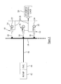
- the staging valve arrangement illustrated in Figure 1 comprises a series of, for example, eighteen staging valves 10 each of which is arranged to receive fuel from a fuel pump 12 and associated fuel metering unit 14 via a supply line 16.
- the supply line 16 is connected to a fuel manifold 18 to which each valve 10 is connected by an associated pig-tail line 20.
- Each staging valve 10 controls the delivery of fuel to an associated integrated pilot burner element 22 and to an associated integrated mains burner element 24.
- Each staging valve 10 takes the form of a valve member arranged to be driven for movement by an electrically operated motor, and a staging control unit 26 is provided which controls the operation of the motor associated with each valve 10 through power and control lines 28.
- the control unit 26 may be a stand alone device, for example located in the fancase region of the engine. Alternatively, it could be integrated into a control unit associated with the engine.
- the interfaces between each of the lines 28 and the respective staging valves 10 have to be hermetically sealed to prevent the possibility of fuel vapour coming into contact with current carrying wires, a potentially hazardous event.
- the sealing arrangement must be capable of withstanding the high temperature environment of the staging valve, as well as the relatively high internal fuel pressure of the valve, which for a typical staging system can be in excess of 2000psi.
- the lines 28 could enter the fuel system near the location of the fuel pump 12 and fuel metering unit 14 in the lower temperature environment of the engine fan case.
- the lines 28 would pass along the inside of the supply line 16 and fuel manifold 18, entering the staging valves via the respective pig-tail lines 20.
- staging control unit 26 would interface with the integrated electronics via an appropriate data bus to provide the necessary sequencing in the operation of the valves.
- the staging valves could be designed as stand alone smart modules with integrated electronic hardware and software. This would negate the need for a separate staging control unit 26 and the associated control lines 28, whilst electrical power to the motor and integrated electronics could be provided along lines running along the inside of the supply line 16, fuel manifold 18 and pig-tails 20, from, for example, an existing power supply module in the engine control unit.
- one or more sensors may be required to provide feedback on one or more operating parameters of the staging valve, fuel system or engine (eg turbine gas temperature).
- a fuel flow meter could be used to provide analogue, rather than digital, control of the staging valve functionality that could be beneficial in providing a fully adaptive staging system. It is recognised that these sensor feedback elements could also be integrated into the preferred embodiment of the control arrangement incorporating the staging control unit 26.
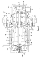
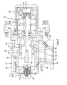
- staging valve 10 in accordance with the invention. It is recognised that this staging valve 10 will either be mounted on the core of the engine close to the manifold 18 or preferably integrated into the design of the corresponding burner assembly for which the staging valve 10 delivers fuel to associated pilot and mains burner elements 22, 24.
- the staging valve 10 illustrated in Figures 2 and 3 comprises a housing 30 of multi-part form.
- the housing 30 is of hollow form, and a motor in the form of an electrically powered stepper motor 32 is located therein.
- the stepper motor 32 includes a rotatable output shaft 34 which is connected to a rotary shaft 36.
- the shaft 36 is supported entirely by the motor shaft 34 and is thus supported by the bearings 38 which, in use, support the motor shaft 34 for rotation.
- the shaft 36 is provided with a screw-thread formation (not shown) which cooperates through a ball or lead screw-type coupling, with a nut 40.
- the nut 40 includes an outwardly extending flange 42 in which openings or recesses 44 are provided, the openings 44 receiving guide pins 46 mounted to a stationary part of the stepper motor 32. The co-operation between the nut 40 and the guide pins 46 serves to resist angular movement of the nut 40 whilst allowing axial translation thereof to occur.
- the flange 42 is received within a recess 48 formed in a cylindrical valve member 50, the co-operation of the flange 42 within the recess 48 being such that translation of the nut 40 along the shaft 36 drives the valve member 50 for axial movement within the housing 30.
- the valve member 50 includes an inwardly extending flange 52 provided with openings through which the pins 46 pass, the pins 46 thus serving to resist angular displacement of the valve member 50 whilst allowing axial translation thereof to occur.
- valve sleeve 54 Located within the housing 30 is a valve sleeve 54, an inner periphery of which is of cylindrical form.
- the valve member 50 slides within the valve sleeve 54, and a dynamic seal member 56 which is carried by the valve member 50 bears against the sleeve 54 to form a seal therebetween.
- the valve sleeve 54 is formed with a pair of first mains outlet openings 58 which are axially aligned with one another, located diametrically opposite one another on the valve sleeve 54 and which, as illustrated in Figure 3 , open into a passage 60 from which fuel can be delivered, in use, to the mains burner element 24.
- the valve sleeve 54 is further provided with a series of second mains outlet openings 62 which are axially aligned with one another and which also open into the passage 60.
- a check valve 64 controlling the passage of fuel between the interior of the valve housing 30 and a pilot flow passage 67 via a pilot outlet opening 65.
- the check valve 64 is open allowing flow of fuel through the staging valve 10 to the pilot burner element 22.
- the check valve 64 is closed, which prevents fuel in the manifold 18 and pig-tail 20 draining via the staging valve 10 to the pilot burner element 22, providing a drip tight seal from the pig-tail 20 to the pilot burner element 22, and ensuring that the manifold 18 and pig-tail 20 are primed with fuel for the next start-up.
- the pilot flow passage 67 is of multi-part form comprising, in part, drillings 66 formed in the housing 30, but also including a region defined by a chamber 68 formed between the housing 30 and the valve sleeve 54.
- a flow restrictor or trimmer device 70 which is preferably adjustable, prior to installation of the staging valve 10, to allow the series of staging valves 10 associated with a particular engine to be matched to one another such that a consistent set of fuel flow restriction paths, commonly referred to as flow number, is provided from the manifold 18 to the pilot burner elements 22, and hence a consistent pilot burner combustion pattern is achieved.
- the housing 30 includes a fuel inlet 72 through which fuel is delivered to the interior of the housing 30.
- the fuel delivered in this manner flows into a chamber 74 within which the motor 32 is located, thereby drowning the motor 32 in fuel.
- Fuel is also able to flow through a passage 76 formed centrally through the shaft 34 of the motor 32, the fuel then flowing through a hollow interior 78 of the shaft 36 to a chamber 80 within which the valve member 50 is located and into which the pilot and mains outlet openings 58, 62, 65 open, depending upon the position of the valve member 50.
- valve member 50 With the valve member 50 in a closed position as illustrated in Figure 3 , the valve member 50 closes the first and second mains outlet openings 58, 62, thus fuel is unable to flow to the passage 60 and from there to the mains burner element 24.
- the operation of the dynamic seal member 56 and the engagement of the end of the valve member 50 with a further seal member 82 located at the end of the chamber 80 serves to ensure that any leakage of fuel from either of the chambers 74, 80 to the passage 60 is prevented, thus providing a drip tight seal to the mains burner element 24.
- valve member 50 can be driven to a fully open position illustrated in Figure 2 in which in addition to the outlet openings 58 being uncovered, the series of second outlet openings 62 are also open. In this position, fuel delivery to the mains burner element 24 increases to a higher rate. Again, fuel will continue to be delivered through the pilot burner element 22, thus cooling of the motor and valve will be maintained.
- the fully open position will be used during high demand conditions such as during take off and climb conditions
- the part-open position will be used during lower demand conditions such as cruise
- the closed (pilot flow only) position will be used under engine idle and descent conditions.
- the motor 32 is driven in the reverse direction to return the valve member 50 towards the position illustrated in Figure 3 , covering either just the series of second outlet openings 62 or both series of outlet openings 58, 62.
- the provision of the second outlet openings 62 in the form of a ring of small openings means that the distance through which the valve member 50 is moved, in use, between its extreme positions is minimised, thereby reducing the size of the valve and any stagnant fuel volumes.
- the high temperature core zone of the engine in which the staging valves 10 are located can have an ambient air temperature in excess of 200°C.
- the internal temperature of the staging valves 10 should ideally not exceed 150°C.
- the temperature should not exceed 150°C in order to avoid fuel lacquering within the staging valve 10, and to maintain the ability of the valve member 50 to move and seal correctly.
- the manner in which the stepper motor 32 is drowned within relatively cool fuel and has relatively cool fuel passing along at least the interior 76 thereof ensures that the motor temperature is maintained at a sufficiently low level to avoid damage to the motor.
- valve housing 30, chamber 80 and associated passages is also such that there is minimum stagnant fuel volume located therein, in particular the size of the passage 60, through which fuel flows to the mains burner element 24, is minimised.
- check valve 64 The nature of the check valve 64 is such that, during all operating modes, the check valve 64 will be open thus fuel will flow through the pilot flow passage 66 and chamber 68 at any time when fuel is being delivered to the staging valve 10, regardless as to whether the valve member 50 is in its closed, partially open or fully open position. Consequently, cooling of the valve and motor occurs at all times that fuel is being supplied through the valve.
- the position of the valve member 50 can be determined by noting the position of the stepper motor 32. As a result, it is thought that no position sensors to provide a separate indication of the position of the valve member will be required. However, should progressive, closed loop control of the valve member be required, rather than the tri-position control described hereinbefore, it may be necessary to integrate a position feedback device, such as a Linear Variable Displacement Transducer (LVDT), into the design of the valve. This device would provide a signal to the staging control unit indicative of the position of the valve member 50. Alternatively a rotary variable differential transducer (RVDT) may be provided for this purpose. For example, it may be arranged to monitor the position of the motor output shaft and hence the position of the valve.
- LVDT Linear Variable Displacement Transducer
- the staging valve 10 described hereinbefore, and illustrated in Figures 2 and 3 takes the form of a conventional linear piston and sleeve type arrangement. It is recognised that the valve could be of rotary form, similar to that described in EP 1903416 , with the stepper motor driving the valve via an integrated gear box, rather than the ball or roller screw arrangement described hereinbefore.
- stepper motor 32 is described herein, it will be appreciated that other forms of motor could be used to drive the valve member 50 for movement.
- a piezo electric device to drive the valve member 50 for movement.
- the use of such a high precision actuating device would enable the staging control, in the form of a stand alone unit or as high temperature electronics, integrated into the design of the staging valve 10, for example, to command rapid perturbations in the fuel flow to the pilot or mains burner elements 22, 24 that could be used to dampen out any instability that may occur in the combustion process (ie mitigation of the aforementioned combustor rumble).
- valve member 50 serves only to control whether or not fuel is delivered to the mains burner element 24.
- the valve member 50 does not control the delivery of fuel through the pilot passage 67 to the pilot burner element 22.
- the pilot check valves 64 in each staging valve 10 on a particular engine need to be accurately matched to ensure that there is consistent and uniform operation of the pilot burner elements 22 around the combustor.
- pilot check valves 64 Any variation in the operation of the pilot check valves 64 could potentially result in, for example, a sudden reduction in fuel flow to the pilot burner elements 22 during a lean burn control operation condition of the engine (ie descent) and a subsequent lean burn blow-out event which is undesirable.
- each staging valve 10 having a controllable pilot valve arrangement instead of a pilot check valve, the fuel flow to the pilot burner elements 22 can be accurately controlled at all engine operating conditions, not only preventing the aforementioned lean burn blow-out condition but also ensuring that over-fuelling does not occur during, for example, engine start-up. Such an arrangement may also permit the trimmer devices 70 to be omitted.
Landscapes
- Engineering & Computer Science (AREA)
- Chemical & Material Sciences (AREA)
- Combustion & Propulsion (AREA)
- Mechanical Engineering (AREA)
- General Engineering & Computer Science (AREA)
- Electrically Driven Valve-Operating Means (AREA)
- Temperature-Responsive Valves (AREA)
Applications Claiming Priority (1)
| Application Number | Priority Date | Filing Date | Title |
|---|---|---|---|
| GB0905710A GB0905710D0 (en) | 2009-04-02 | 2009-04-02 | Staging valve |
Publications (3)
| Publication Number | Publication Date |
|---|---|
| EP2236924A2 true EP2236924A2 (fr) | 2010-10-06 |
| EP2236924A3 EP2236924A3 (fr) | 2012-05-30 |
| EP2236924B1 EP2236924B1 (fr) | 2014-01-22 |
Family
ID=40749973
Family Applications (1)
| Application Number | Title | Priority Date | Filing Date |
|---|---|---|---|
| EP20100250666 Not-in-force EP2236924B1 (fr) | 2009-04-02 | 2010-03-30 | Agencement de soupape de stratification et soupape de stratification correspondante |
Country Status (3)
| Country | Link |
|---|---|
| US (1) | US8739544B2 (fr) |
| EP (1) | EP2236924B1 (fr) |
| GB (1) | GB0905710D0 (fr) |
Cited By (2)
| Publication number | Priority date | Publication date | Assignee | Title |
|---|---|---|---|---|
| US11041440B2 (en) | 2018-02-02 | 2021-06-22 | Rolls-Royce Plc | Fuel flow valve |
| EP4215736A3 (fr) * | 2022-01-21 | 2023-11-08 | Hamilton Sundstrand Corporation | Système de régulation de débit actif |
Families Citing this family (1)
| Publication number | Priority date | Publication date | Assignee | Title |
|---|---|---|---|---|
| US11703134B2 (en) | 2021-08-20 | 2023-07-18 | Hamilton Sundstrand Corporation | Metering valve with mid-stroke shutoff |
Citations (2)
| Publication number | Priority date | Publication date | Assignee | Title |
|---|---|---|---|---|
| EP1903416A2 (fr) | 2006-09-19 | 2008-03-26 | Goodrich Control Systems Limited | Agencement de soupape de dosage rotative |
| EP2063087A2 (fr) | 2007-11-20 | 2009-05-27 | Goodrich Control Systems Ltd | Dispositif d'alimentation étagée de carburant |
Family Cites Families (16)
| Publication number | Priority date | Publication date | Assignee | Title |
|---|---|---|---|---|
| US5544478A (en) * | 1994-11-15 | 1996-08-13 | General Electric Company | Optical sensing of combustion dynamics |
| US5735117A (en) * | 1995-08-18 | 1998-04-07 | Fuel Systems Textron, Inc. | Staged fuel injection system with shuttle valve and fuel injector therefor |
| EP0982838B1 (fr) * | 1998-02-24 | 2007-04-11 | Mitsubishi Denki Kabushiki Kaisha | Vanne de regulation de debit motorisee |
| US6216677B1 (en) * | 1999-09-10 | 2001-04-17 | Eaton Corporation | EGR assembly mounted on exhaust system of a heavy duty diesel engine |
| US6393823B1 (en) * | 1999-11-05 | 2002-05-28 | General Electric Company | Methods for fuel nozzle staging for gas turbine engines |
| US6435169B1 (en) * | 2000-03-17 | 2002-08-20 | Borgwarner Inc. | Integrated motor and controller for turbochargers, EGR valves and the like |
| US6405524B1 (en) * | 2000-08-16 | 2002-06-18 | General Electric Company | Apparatus for decreasing gas turbine combustor emissions |
| US6989574B2 (en) * | 2000-08-24 | 2006-01-24 | Heetronix | High temperature circuit structures with thin film layer |
| US6810674B2 (en) * | 2002-07-18 | 2004-11-02 | Argo-Tech Corporation | Fuel delivery system |
| US7007476B2 (en) * | 2003-04-11 | 2006-03-07 | Parker-Hannifin Corporation | Gas turbine fuel system staging valves |
| US6981359B2 (en) * | 2003-06-16 | 2006-01-03 | Woodward Governor Company | Centrifugal pump fuel system and method for gas turbine engine |
| GB0329626D0 (en) * | 2003-12-23 | 2004-01-28 | Goodrich Control Sys Ltd | Fuel system |
| US7036302B2 (en) * | 2004-03-15 | 2006-05-02 | General Electric Company | Controlled pressure fuel nozzle system |
| US7726951B2 (en) * | 2004-06-18 | 2010-06-01 | Jansen's Aircraft Systems Controls, Inc. | Fuel control module |
| DE102008032565A1 (de) | 2008-07-11 | 2010-01-14 | Rolls-Royce Deutschland Ltd & Co Kg | Brennstoffzufuhrsystem für ein Gasturbinentriebwerk |
| GB201104161D0 (en) * | 2011-03-11 | 2011-04-27 | Rolls Royce Goodrich Engine Control Systems Ltd | Fuel system |
-
2009
- 2009-04-02 GB GB0905710A patent/GB0905710D0/en not_active Ceased
-
2010
- 2010-03-29 US US12/748,841 patent/US8739544B2/en not_active Expired - Fee Related
- 2010-03-30 EP EP20100250666 patent/EP2236924B1/fr not_active Not-in-force
Patent Citations (2)
| Publication number | Priority date | Publication date | Assignee | Title |
|---|---|---|---|---|
| EP1903416A2 (fr) | 2006-09-19 | 2008-03-26 | Goodrich Control Systems Limited | Agencement de soupape de dosage rotative |
| EP2063087A2 (fr) | 2007-11-20 | 2009-05-27 | Goodrich Control Systems Ltd | Dispositif d'alimentation étagée de carburant |
Cited By (3)
| Publication number | Priority date | Publication date | Assignee | Title |
|---|---|---|---|---|
| US11041440B2 (en) | 2018-02-02 | 2021-06-22 | Rolls-Royce Plc | Fuel flow valve |
| EP4215736A3 (fr) * | 2022-01-21 | 2023-11-08 | Hamilton Sundstrand Corporation | Système de régulation de débit actif |
| US11914408B2 (en) | 2022-01-21 | 2024-02-27 | Hamilton Sundstrand Corporation | Active flow control system |
Also Published As
| Publication number | Publication date |
|---|---|
| EP2236924A3 (fr) | 2012-05-30 |
| GB0905710D0 (en) | 2009-05-20 |
| US8739544B2 (en) | 2014-06-03 |
| US20100252758A1 (en) | 2010-10-07 |
| EP2236924B1 (fr) | 2014-01-22 |
Similar Documents
| Publication | Publication Date | Title |
|---|---|---|
| US9133772B2 (en) | Fuel system | |
| US10288294B2 (en) | Combustion staging system | |
| EP1416206B1 (fr) | Soupape avec piston d'équilibrage de pression | |
| GB2563658B (en) | Combustion staging system for fuel injectors of a gas turbine engine | |
| US8720482B2 (en) | Fuel system | |
| US20100170574A1 (en) | Gas mixing pump with variable injection section | |
| US10563589B2 (en) | Engine overspeed protection with thrust control | |
| US6786702B2 (en) | Fuel metering unit | |
| CN101922322B (zh) | 带有蓄压器的凸轮轴相位调整器 | |
| US20120167587A1 (en) | Gas turbine engine with bleed air system | |
| EP2236924B1 (fr) | Agencement de soupape de stratification et soupape de stratification correspondante | |
| US8636467B2 (en) | Variable geometry turbine | |
| JP5664176B2 (ja) | 燃料供給システム | |
| EP2184466A2 (fr) | Procédé de réallumage de moteur d'avion | |
| WO2017054971A1 (fr) | Agencement de compresseur et turbine à gaz | |
| US11365825B2 (en) | Actuator fail fix system | |
| EP2405115B1 (fr) | Agencement de valve à flux divisé | |
| US10519869B2 (en) | Electrical and mechanical connections through firewall | |
| US20160377000A1 (en) | Method for operating a gas turbine installation and the same | |
| US12000340B1 (en) | Gas turbine engine lubricant flow control system | |
| CN107061021B (zh) | 一种发动机机械液压燃油流量辅助计量调节装置 | |
| EP4424977A1 (fr) | Système de commande de débit de lubrifiant de moteur à turbine à gaz | |
| RU2352802C1 (ru) | Система топливопитания и регулирования газотурбинного двигателя | |
| EP3943815A1 (fr) | Brûleur à plusieurs étages à combustible liquide | |
| CN105443252B (zh) | 一种无级自由调速柴油发动机 |
Legal Events
| Date | Code | Title | Description |
|---|---|---|---|
| PUAI | Public reference made under article 153(3) epc to a published international application that has entered the european phase |
Free format text: ORIGINAL CODE: 0009012 |
|
| AK | Designated contracting states |
Kind code of ref document: A2 Designated state(s): AT BE BG CH CY CZ DE DK EE ES FI FR GB GR HR HU IE IS IT LI LT LU LV MC MK MT NL NO PL PT RO SE SI SK SM TR |
|
| AX | Request for extension of the european patent |
Extension state: AL BA ME RS |
|
| PUAL | Search report despatched |
Free format text: ORIGINAL CODE: 0009013 |
|
| AK | Designated contracting states |
Kind code of ref document: A3 Designated state(s): AT BE BG CH CY CZ DE DK EE ES FI FR GB GR HR HU IE IS IT LI LT LU LV MC MK MT NL NO PL PT RO SE SI SK SM TR |
|
| AX | Request for extension of the european patent |
Extension state: AL BA ME RS |
|
| RIC1 | Information provided on ipc code assigned before grant |
Ipc: F23K 5/04 20060101ALI20120423BHEP Ipc: F02C 7/228 20060101ALI20120423BHEP Ipc: F23K 5/14 20060101AFI20120423BHEP |
|
| 17P | Request for examination filed |
Effective date: 20121112 |
|
| RAP1 | Party data changed (applicant data changed or rights of an application transferred) |
Owner name: ROLLS-ROYCE ENGINE CONTROL SYSTEMS LTD |
|
| RIC1 | Information provided on ipc code assigned before grant |
Ipc: F23K 5/04 20060101ALI20130326BHEP Ipc: F02C 7/228 20060101ALI20130326BHEP Ipc: F23K 5/14 20060101AFI20130326BHEP |
|
| GRAJ | Information related to disapproval of communication of intention to grant by the applicant or resumption of examination proceedings by the epo deleted |
Free format text: ORIGINAL CODE: EPIDOSDIGR1 |
|
| GRAP | Despatch of communication of intention to grant a patent |
Free format text: ORIGINAL CODE: EPIDOSNIGR1 |
|
| GRAP | Despatch of communication of intention to grant a patent |
Free format text: ORIGINAL CODE: EPIDOSNIGR1 |
|
| INTG | Intention to grant announced |
Effective date: 20130620 |
|
| GRAP | Despatch of communication of intention to grant a patent |
Free format text: ORIGINAL CODE: EPIDOSNIGR1 |
|
| INTG | Intention to grant announced |
Effective date: 20131001 |
|
| GRAS | Grant fee paid |
Free format text: ORIGINAL CODE: EPIDOSNIGR3 |
|
| GRAA | (expected) grant |
Free format text: ORIGINAL CODE: 0009210 |
|
| AK | Designated contracting states |
Kind code of ref document: B1 Designated state(s): AT BE BG CH CY CZ DE DK EE ES FI FR GB GR HR HU IE IS IT LI LT LU LV MC MK MT NL NO PL PT RO SE SI SK SM TR |
|
| REG | Reference to a national code |
Ref country code: GB Ref legal event code: FG4D |
|
| REG | Reference to a national code |
Ref country code: CH Ref legal event code: EP |
|
| REG | Reference to a national code |
Ref country code: AT Ref legal event code: REF Ref document number: 650982 Country of ref document: AT Kind code of ref document: T Effective date: 20140215 |
|
| REG | Reference to a national code |
Ref country code: IE Ref legal event code: FG4D |
|
| REG | Reference to a national code |
Ref country code: DE Ref legal event code: R096 Ref document number: 602010013261 Country of ref document: DE Effective date: 20140306 |
|
| RAP2 | Party data changed (patent owner data changed or rights of a patent transferred) |
Owner name: ROLLS-ROYCE CONTROLS AND DATA SERVICES LIMITED |
|
| REG | Reference to a national code |
Ref country code: NL Ref legal event code: VDEP Effective date: 20140122 |
|
| REG | Reference to a national code |
Ref country code: AT Ref legal event code: MK05 Ref document number: 650982 Country of ref document: AT Kind code of ref document: T Effective date: 20140122 |
|
| REG | Reference to a national code |
Ref country code: LT Ref legal event code: MG4D |
|
| PG25 | Lapsed in a contracting state [announced via postgrant information from national office to epo] |
Ref country code: IS Free format text: LAPSE BECAUSE OF FAILURE TO SUBMIT A TRANSLATION OF THE DESCRIPTION OR TO PAY THE FEE WITHIN THE PRESCRIBED TIME-LIMIT Effective date: 20140522 Ref country code: LT Free format text: LAPSE BECAUSE OF FAILURE TO SUBMIT A TRANSLATION OF THE DESCRIPTION OR TO PAY THE FEE WITHIN THE PRESCRIBED TIME-LIMIT Effective date: 20140122 Ref country code: NO Free format text: LAPSE BECAUSE OF FAILURE TO SUBMIT A TRANSLATION OF THE DESCRIPTION OR TO PAY THE FEE WITHIN THE PRESCRIBED TIME-LIMIT Effective date: 20140422 |
|
| PG25 | Lapsed in a contracting state [announced via postgrant information from national office to epo] |
Ref country code: ES Free format text: LAPSE BECAUSE OF FAILURE TO SUBMIT A TRANSLATION OF THE DESCRIPTION OR TO PAY THE FEE WITHIN THE PRESCRIBED TIME-LIMIT Effective date: 20140122 Ref country code: CY Free format text: LAPSE BECAUSE OF FAILURE TO SUBMIT A TRANSLATION OF THE DESCRIPTION OR TO PAY THE FEE WITHIN THE PRESCRIBED TIME-LIMIT Effective date: 20140122 Ref country code: SE Free format text: LAPSE BECAUSE OF FAILURE TO SUBMIT A TRANSLATION OF THE DESCRIPTION OR TO PAY THE FEE WITHIN THE PRESCRIBED TIME-LIMIT Effective date: 20140122 Ref country code: PT Free format text: LAPSE BECAUSE OF FAILURE TO SUBMIT A TRANSLATION OF THE DESCRIPTION OR TO PAY THE FEE WITHIN THE PRESCRIBED TIME-LIMIT Effective date: 20140522 Ref country code: AT Free format text: LAPSE BECAUSE OF FAILURE TO SUBMIT A TRANSLATION OF THE DESCRIPTION OR TO PAY THE FEE WITHIN THE PRESCRIBED TIME-LIMIT Effective date: 20140122 Ref country code: FI Free format text: LAPSE BECAUSE OF FAILURE TO SUBMIT A TRANSLATION OF THE DESCRIPTION OR TO PAY THE FEE WITHIN THE PRESCRIBED TIME-LIMIT Effective date: 20140122 Ref country code: NL Free format text: LAPSE BECAUSE OF FAILURE TO SUBMIT A TRANSLATION OF THE DESCRIPTION OR TO PAY THE FEE WITHIN THE PRESCRIBED TIME-LIMIT Effective date: 20140122 |
|
| PG25 | Lapsed in a contracting state [announced via postgrant information from national office to epo] |
Ref country code: BE Free format text: LAPSE BECAUSE OF FAILURE TO SUBMIT A TRANSLATION OF THE DESCRIPTION OR TO PAY THE FEE WITHIN THE PRESCRIBED TIME-LIMIT Effective date: 20140122 Ref country code: LV Free format text: LAPSE BECAUSE OF FAILURE TO SUBMIT A TRANSLATION OF THE DESCRIPTION OR TO PAY THE FEE WITHIN THE PRESCRIBED TIME-LIMIT Effective date: 20140122 Ref country code: HR Free format text: LAPSE BECAUSE OF FAILURE TO SUBMIT A TRANSLATION OF THE DESCRIPTION OR TO PAY THE FEE WITHIN THE PRESCRIBED TIME-LIMIT Effective date: 20140122 |
|
| REG | Reference to a national code |
Ref country code: DE Ref legal event code: R097 Ref document number: 602010013261 Country of ref document: DE |
|
| PG25 | Lapsed in a contracting state [announced via postgrant information from national office to epo] |
Ref country code: DK Free format text: LAPSE BECAUSE OF FAILURE TO SUBMIT A TRANSLATION OF THE DESCRIPTION OR TO PAY THE FEE WITHIN THE PRESCRIBED TIME-LIMIT Effective date: 20140122 Ref country code: EE Free format text: LAPSE BECAUSE OF FAILURE TO SUBMIT A TRANSLATION OF THE DESCRIPTION OR TO PAY THE FEE WITHIN THE PRESCRIBED TIME-LIMIT Effective date: 20140122 Ref country code: RO Free format text: LAPSE BECAUSE OF FAILURE TO SUBMIT A TRANSLATION OF THE DESCRIPTION OR TO PAY THE FEE WITHIN THE PRESCRIBED TIME-LIMIT Effective date: 20140122 Ref country code: LU Free format text: LAPSE BECAUSE OF FAILURE TO SUBMIT A TRANSLATION OF THE DESCRIPTION OR TO PAY THE FEE WITHIN THE PRESCRIBED TIME-LIMIT Effective date: 20140330 Ref country code: CZ Free format text: LAPSE BECAUSE OF FAILURE TO SUBMIT A TRANSLATION OF THE DESCRIPTION OR TO PAY THE FEE WITHIN THE PRESCRIBED TIME-LIMIT Effective date: 20140122 |
|
| REG | Reference to a national code |
Ref country code: CH Ref legal event code: PL |
|
| PG25 | Lapsed in a contracting state [announced via postgrant information from national office to epo] |
Ref country code: PL Free format text: LAPSE BECAUSE OF FAILURE TO SUBMIT A TRANSLATION OF THE DESCRIPTION OR TO PAY THE FEE WITHIN THE PRESCRIBED TIME-LIMIT Effective date: 20140122 Ref country code: SK Free format text: LAPSE BECAUSE OF FAILURE TO SUBMIT A TRANSLATION OF THE DESCRIPTION OR TO PAY THE FEE WITHIN THE PRESCRIBED TIME-LIMIT Effective date: 20140122 |
|
| PLBE | No opposition filed within time limit |
Free format text: ORIGINAL CODE: 0009261 |
|
| STAA | Information on the status of an ep patent application or granted ep patent |
Free format text: STATUS: NO OPPOSITION FILED WITHIN TIME LIMIT |
|
| 26N | No opposition filed |
Effective date: 20141023 |
|
| REG | Reference to a national code |
Ref country code: IE Ref legal event code: MM4A |
|
| PG25 | Lapsed in a contracting state [announced via postgrant information from national office to epo] |
Ref country code: IE Free format text: LAPSE BECAUSE OF NON-PAYMENT OF DUE FEES Effective date: 20140330 Ref country code: LI Free format text: LAPSE BECAUSE OF NON-PAYMENT OF DUE FEES Effective date: 20140331 Ref country code: CH Free format text: LAPSE BECAUSE OF NON-PAYMENT OF DUE FEES Effective date: 20140331 |
|
| REG | Reference to a national code |
Ref country code: DE Ref legal event code: R097 Ref document number: 602010013261 Country of ref document: DE Effective date: 20141023 |
|
| PG25 | Lapsed in a contracting state [announced via postgrant information from national office to epo] |
Ref country code: SI Free format text: LAPSE BECAUSE OF FAILURE TO SUBMIT A TRANSLATION OF THE DESCRIPTION OR TO PAY THE FEE WITHIN THE PRESCRIBED TIME-LIMIT Effective date: 20140122 |
|
| PG25 | Lapsed in a contracting state [announced via postgrant information from national office to epo] |
Ref country code: MT Free format text: LAPSE BECAUSE OF FAILURE TO SUBMIT A TRANSLATION OF THE DESCRIPTION OR TO PAY THE FEE WITHIN THE PRESCRIBED TIME-LIMIT Effective date: 20140122 |
|
| REG | Reference to a national code |
Ref country code: FR Ref legal event code: PLFP Year of fee payment: 7 |
|
| PG25 | Lapsed in a contracting state [announced via postgrant information from national office to epo] |
Ref country code: SM Free format text: LAPSE BECAUSE OF FAILURE TO SUBMIT A TRANSLATION OF THE DESCRIPTION OR TO PAY THE FEE WITHIN THE PRESCRIBED TIME-LIMIT Effective date: 20140122 |
|
| PG25 | Lapsed in a contracting state [announced via postgrant information from national office to epo] |
Ref country code: MC Free format text: LAPSE BECAUSE OF FAILURE TO SUBMIT A TRANSLATION OF THE DESCRIPTION OR TO PAY THE FEE WITHIN THE PRESCRIBED TIME-LIMIT Effective date: 20140122 |
|
| PG25 | Lapsed in a contracting state [announced via postgrant information from national office to epo] |
Ref country code: BG Free format text: LAPSE BECAUSE OF FAILURE TO SUBMIT A TRANSLATION OF THE DESCRIPTION OR TO PAY THE FEE WITHIN THE PRESCRIBED TIME-LIMIT Effective date: 20140122 Ref country code: IT Free format text: LAPSE BECAUSE OF FAILURE TO SUBMIT A TRANSLATION OF THE DESCRIPTION OR TO PAY THE FEE WITHIN THE PRESCRIBED TIME-LIMIT Effective date: 20140122 Ref country code: GR Free format text: LAPSE BECAUSE OF FAILURE TO SUBMIT A TRANSLATION OF THE DESCRIPTION OR TO PAY THE FEE WITHIN THE PRESCRIBED TIME-LIMIT Effective date: 20140423 |
|
| PG25 | Lapsed in a contracting state [announced via postgrant information from national office to epo] |
Ref country code: HU Free format text: LAPSE BECAUSE OF FAILURE TO SUBMIT A TRANSLATION OF THE DESCRIPTION OR TO PAY THE FEE WITHIN THE PRESCRIBED TIME-LIMIT; INVALID AB INITIO Effective date: 20100330 Ref country code: TR Free format text: LAPSE BECAUSE OF FAILURE TO SUBMIT A TRANSLATION OF THE DESCRIPTION OR TO PAY THE FEE WITHIN THE PRESCRIBED TIME-LIMIT Effective date: 20140122 |
|
| REG | Reference to a national code |
Ref country code: DE Ref legal event code: R082 Ref document number: 602010013261 Country of ref document: DE Representative=s name: LEINWEBER & ZIMMERMANN PATENTANWALTS-PARTG MBB, DE Ref country code: DE Ref legal event code: R081 Ref document number: 602010013261 Country of ref document: DE Owner name: ROLLS-ROYCE PLC, GB Free format text: FORMER OWNER: ROLLS-ROYCE ENGINE CONTROL SYSTEMS LTD, DERBY, GB Ref country code: DE Ref legal event code: R082 Ref document number: 602010013261 Country of ref document: DE Representative=s name: LEINWEBER & ZIMMERMANN, DE |
|
| REG | Reference to a national code |
Ref country code: GB Ref legal event code: 732E Free format text: REGISTERED BETWEEN 20170126 AND 20170201 |
|
| REG | Reference to a national code |
Ref country code: FR Ref legal event code: PLFP Year of fee payment: 8 |
|
| REG | Reference to a national code |
Ref country code: FR Ref legal event code: TP Owner name: ROLLS-ROYCE PLC, GB Effective date: 20170601 |
|
| REG | Reference to a national code |
Ref country code: FR Ref legal event code: PLFP Year of fee payment: 9 |
|
| PG25 | Lapsed in a contracting state [announced via postgrant information from national office to epo] |
Ref country code: MK Free format text: LAPSE BECAUSE OF FAILURE TO SUBMIT A TRANSLATION OF THE DESCRIPTION OR TO PAY THE FEE WITHIN THE PRESCRIBED TIME-LIMIT Effective date: 20140122 |
|
| PGFP | Annual fee paid to national office [announced via postgrant information from national office to epo] |
Ref country code: DE Payment date: 20200327 Year of fee payment: 11 Ref country code: GB Payment date: 20200327 Year of fee payment: 11 |
|
| PGFP | Annual fee paid to national office [announced via postgrant information from national office to epo] |
Ref country code: FR Payment date: 20200325 Year of fee payment: 11 |
|
| REG | Reference to a national code |
Ref country code: DE Ref legal event code: R119 Ref document number: 602010013261 Country of ref document: DE |
|
| GBPC | Gb: european patent ceased through non-payment of renewal fee |
Effective date: 20210330 |
|
| PG25 | Lapsed in a contracting state [announced via postgrant information from national office to epo] |
Ref country code: DE Free format text: LAPSE BECAUSE OF NON-PAYMENT OF DUE FEES Effective date: 20211001 Ref country code: FR Free format text: LAPSE BECAUSE OF NON-PAYMENT OF DUE FEES Effective date: 20210331 Ref country code: GB Free format text: LAPSE BECAUSE OF NON-PAYMENT OF DUE FEES Effective date: 20210330 |