EP4424977A1 - Système de commande de débit de lubrifiant de moteur à turbine à gaz - Google Patents
Système de commande de débit de lubrifiant de moteur à turbine à gaz Download PDFInfo
- Publication number
- EP4424977A1 EP4424977A1 EP24156671.0A EP24156671A EP4424977A1 EP 4424977 A1 EP4424977 A1 EP 4424977A1 EP 24156671 A EP24156671 A EP 24156671A EP 4424977 A1 EP4424977 A1 EP 4424977A1
- Authority
- EP
- European Patent Office
- Prior art keywords
- lubricant
- valve element
- flow
- valve
- gas turbine
- Prior art date
- Legal status (The legal status is an assumption and is not a legal conclusion. Google has not performed a legal analysis and makes no representation as to the accuracy of the status listed.)
- Pending
Links
Images



Classifications
-
- F—MECHANICAL ENGINEERING; LIGHTING; HEATING; WEAPONS; BLASTING
- F01—MACHINES OR ENGINES IN GENERAL; ENGINE PLANTS IN GENERAL; STEAM ENGINES
- F01D—NON-POSITIVE DISPLACEMENT MACHINES OR ENGINES, e.g. STEAM TURBINES
- F01D17/00—Regulating or controlling by varying flow
- F01D17/10—Final actuators
- F01D17/105—Final actuators by passing part of the fluid
-
- F—MECHANICAL ENGINEERING; LIGHTING; HEATING; WEAPONS; BLASTING
- F01—MACHINES OR ENGINES IN GENERAL; ENGINE PLANTS IN GENERAL; STEAM ENGINES
- F01D—NON-POSITIVE DISPLACEMENT MACHINES OR ENGINES, e.g. STEAM TURBINES
- F01D25/00—Component parts, details, or accessories, not provided for in, or of interest apart from, other groups
- F01D25/18—Lubricating arrangements
-
- F—MECHANICAL ENGINEERING; LIGHTING; HEATING; WEAPONS; BLASTING
- F02—COMBUSTION ENGINES; HOT-GAS OR COMBUSTION-PRODUCT ENGINE PLANTS
- F02K—JET-PROPULSION PLANTS
- F02K3/00—Plants including a gas turbine driving a compressor or a ducted fan
- F02K3/02—Plants including a gas turbine driving a compressor or a ducted fan in which part of the working fluid by-passes the turbine and combustion chamber
- F02K3/04—Plants including a gas turbine driving a compressor or a ducted fan in which part of the working fluid by-passes the turbine and combustion chamber the plant including ducted fans, i.e. fans with high volume, low pressure outputs, for augmenting the jet thrust, e.g. of double-flow type
- F02K3/06—Plants including a gas turbine driving a compressor or a ducted fan in which part of the working fluid by-passes the turbine and combustion chamber the plant including ducted fans, i.e. fans with high volume, low pressure outputs, for augmenting the jet thrust, e.g. of double-flow type with front fan
-
- F—MECHANICAL ENGINEERING; LIGHTING; HEATING; WEAPONS; BLASTING
- F05—INDEXING SCHEMES RELATING TO ENGINES OR PUMPS IN VARIOUS SUBCLASSES OF CLASSES F01-F04
- F05D—INDEXING SCHEME FOR ASPECTS RELATING TO NON-POSITIVE-DISPLACEMENT MACHINES OR ENGINES, GAS-TURBINES OR JET-PROPULSION PLANTS
- F05D2260/00—Function
- F05D2260/40—Transmission of power
- F05D2260/403—Transmission of power through the shape of the drive components
- F05D2260/4031—Transmission of power through the shape of the drive components as in toothed gearing
-
- F—MECHANICAL ENGINEERING; LIGHTING; HEATING; WEAPONS; BLASTING
- F05—INDEXING SCHEMES RELATING TO ENGINES OR PUMPS IN VARIOUS SUBCLASSES OF CLASSES F01-F04
- F05D—INDEXING SCHEME FOR ASPECTS RELATING TO NON-POSITIVE-DISPLACEMENT MACHINES OR ENGINES, GAS-TURBINES OR JET-PROPULSION PLANTS
- F05D2260/00—Function
- F05D2260/98—Lubrication
-
- F—MECHANICAL ENGINEERING; LIGHTING; HEATING; WEAPONS; BLASTING
- F05—INDEXING SCHEMES RELATING TO ENGINES OR PUMPS IN VARIOUS SUBCLASSES OF CLASSES F01-F04
- F05D—INDEXING SCHEME FOR ASPECTS RELATING TO NON-POSITIVE-DISPLACEMENT MACHINES OR ENGINES, GAS-TURBINES OR JET-PROPULSION PLANTS
- F05D2270/00—Control
- F05D2270/30—Control parameters, e.g. input parameters
- F05D2270/301—Pressure
-
- F—MECHANICAL ENGINEERING; LIGHTING; HEATING; WEAPONS; BLASTING
- F16—ENGINEERING ELEMENTS AND UNITS; GENERAL MEASURES FOR PRODUCING AND MAINTAINING EFFECTIVE FUNCTIONING OF MACHINES OR INSTALLATIONS; THERMAL INSULATION IN GENERAL
- F16K—VALVES; TAPS; COCKS; ACTUATING-FLOATS; DEVICES FOR VENTING OR AERATING
- F16K3/00—Gate valves or sliding valves, i.e. cut-off apparatus with closing members having a sliding movement along the seat for opening and closing
- F16K3/22—Gate valves or sliding valves, i.e. cut-off apparatus with closing members having a sliding movement along the seat for opening and closing with sealing faces shaped as surfaces of solids of revolution
- F16K3/24—Gate valves or sliding valves, i.e. cut-off apparatus with closing members having a sliding movement along the seat for opening and closing with sealing faces shaped as surfaces of solids of revolution with cylindrical valve members
Definitions
- This disclosure generally relates to gas turbine engines and, more particularly, relates to system for controlling lubricant flow to a component in a gas turbine engine.
- turbofan jet engines include a fan reduction gearbox coupled between the shaft of the gas turbine engine, which rotates at a high rate of speed, and the turbofan shaft, which operates more efficiently when rotating at a substantially lower speed.
- engine driven gearboxes are typically supplied with oil by an oil pump, such as a positive displacement pump, that is directly or indirectly driven by the engine shaft.
- the oil supply system is sized to ensure that the supply of the oil to the gears is sufficient to maintain proper operation at the maximum gear torque level.
- the supply of oil to the gearbox may exceed the amount necessary, causing the gearbox to churn the excess lubricant, and reducing oil service life.
- gas turbine engines include a pneumatically actuated flow reduction valve, which regulates lubricant flow to the fan reduction gearbox (or other accessories requiring lubrication) as a function of engine load. More specifically, lubricant flow is regulated as a function of compressor discharge pressure, which correlates well gear torque output of the engine.
- compressor discharge pressure which correlates well gear torque output of the engine.
- the mechanical valve piston can become jammed due to excessive heating and friction.
- high-pressure, high-temperature air from the compressor enters the valve it increases the temperature of not only the valve body, but also the lubricant flowing through the valve. This can lead to decreased lubricant density and viscosity, which can increase lubricant flow into the gearbox and reduce the system efficiency.
- a lubricant supply system that does not exhibit the above-noted drawbacks. Namely, a lubricant supply system that includes a flow reduction valve that does not use high-pressure, high-temperature air from the compressor and thereby does not increase the temperature of the lubricant flowing through the valve.
- the present disclosure addresses at least this need.
- a system for controlling lubricant flow to a component in a gas turbine engine includes a control valve, an electromechanical actuator, and an engine controller.
- the control valve includes a lubricant inlet, a lubricant outlet, and a valve element.
- the lubricant inlet is in fluid communication with a pressurized lubricant source
- the lubricant outlet is in fluid communication with the gas turbine engine component
- the valve element movable to a plurality of valve positions.
- the electromechanical valve actuator is coupled to the valve element and is responsive to actuator commands to move the valve element to the plurality of valve element positions.
- the engine controller is coupled to receive a pressure sensor signal indicative of a compressor pressure sensed in the gas turbine engine.
- the engine controller is configured, in response to the pressure sensor signal, to (i) determine a commanded valve element position and (ii) supply the actuator commands to the electromechanical valve actuator that cause the electromechanical valve actuator to move the valve element to the commanded valve element position, to thereby control lubricant flow to the component in the gas turbine engine.
- a system for controlling lubricant flow to a component in a gas turbine engine includes a control valve, an electromechanical actuator, and an engine controller.
- the control valve includes a lubricant inlet, a lubricant outlet, and a valve element.
- the lubricant inlet is in fluid communication with a pressurized lubricant source
- the lubricant outlet is in fluid communication with the gas turbine engine component
- the valve element movable to a plurality of valve positions.
- the electromechanical valve actuator is coupled to the valve element and is responsive to actuator commands to move the valve element to the plurality of valve element positions.
- the plurality of valve element positions include a first end position, a plurality of throttle positions, and a second end position.
- the engine controller is coupled to receive a pressure sensor signal indicative of a compressor pressure sensed in the gas turbine engine.
- the engine controller is configured, in response to the pressure sensor signal, to (i) determine a commanded valve element position and (ii) supply the actuator commands to the electromechanical valve actuator that cause the electromechanical valve actuator to move the valve element to the commanded valve element position, to thereby control lubricant flow to the component in the gas turbine engine.
- the control valve further includes a flow chamber disposed between the lubricant inlet and the lubricant outlet, and the flow chamber has a plurality of first flow orifices and a plurality of second flow orifices.
- the first flow orifices are disposed downstream of the lubricant inlet and are configured such that lubricant may continuously flow through the first flow orifices regardless of the valve element position.
- the second flow orifices are disposed downstream of the first flow orifices and are configured such that lubricant flow through the second flow orifices is controlled based on the valve element position.
- a gas turbine engine system includes a gas turbine engine and a lubrication control system.
- the gas turbine engine includes at least a an intake section, a compressor section, a combustion section, a turbine section, an exhaust section, and a fan reduction gearbox.
- the lubrication control system controls lubricant flow to the fan reduction gearbox and includes a control valve, an electromechanical actuator, and an engine controller.
- the control valve includes a lubricant inlet, a lubricant outlet, and a valve element.
- the lubricant inlet is in fluid communication with a pressurized lubricant source
- the lubricant outlet is in fluid communication with the gas turbine engine component
- the valve element movable to a plurality of valve positions.
- the electromechanical valve actuator is coupled to the valve element and is responsive to actuator commands to move the valve element to the plurality of valve element positions.
- the engine controller is coupled to receive a pressure sensor signal indicative of a compressor pressure sensed in the gas turbine engine.
- the engine controller is configured, in response to the pressure sensor signal, to (i) determine a commanded valve element position and (ii) supply the actuator commands to the electromechanical valve actuator that cause the electromechanical valve actuator to move the valve element to the commanded valve element position, to thereby control lubricant flow to the fan reduction gearbox.
- the gas turbine engine system 100 includes a gas turbine engine 110 and an engine controller 112.
- the gas turbine engine 110 which is disposed in an engine housing 102, includes an intake section 115, a compressor section 120, a combustion section 130, a turbine section 140, and an exhaust section 150.
- the compressor section 120 and turbine section 140 are operably coupled to a shaft assembly 160 for rotation within the housing 102.
- a fluid e.g., air
- a fluid is drawn into the engine housing 110 through the intake section 115 and into the compressor section 120.
- the compressor section 120 which in the depicted embodiment is configured as an axial-centrifugal compressor, includes an axial compressor 122 and a centrifugal compressor 124. Together, these compressors 122, 124 compress, and thus increase the pressure of, the fluid entering the engine 100 and supply the compressed fluid into the combustion section 130. It will be appreciated that in other embodiments, the compressor section 120 may be implemented using any one of numerous other types of compressors.
- the combustion section 130 includes a combustor air inlet 132 and a combustion chamber 134.
- the combustor air inlet 132 is in fluid communication with the axial-centrifugal compressor 120, and it directs the compressed fluid into the combustion chamber 134.
- the compressed fluid is mixed with fuel and is combusted in the combustion chamber 134. Hot exhaust fluids are then directed into the turbine section 140.
- the hot exhaust fluids expand through, and rotate, the turbine section 140 prior to being exhausted through the exhaust section 150.
- the turbine section 140 rotates to drive equipment in the gas turbine engine 110 via rotors or spools concentrically disposed about an axis of rotation 162 within the shaft assembly 160.
- the turbine section 140 may include one or more rotors 142, 144 driven by the expanding hot exhaust fluids to rotate the shaft assembly 160 and drive the axial and centrifugal compressors 122, 124 and, at least in the depicted embodiment, an inlet fan 116 via a plurality of gears housed within a fan reduction gearbox 118.
- the overall operation of the gas turbine engine 110 is controlled via the engine controller 112.
- the engine controller 112 as is generally known, is used to control the output power of the gas turbine engine 110 by, for example, controlling fuel flow rate to the gas turbine engine 110, as well as controlling airflow through the gas turbine engine 110.
- the engine controller 110 receives signals from a plurality of sensors 114 that are disposed at various locations on and within the gas turbine engine 110.
- the sensors 114 are used to sense various physical parameters associated with the gas turbine engine 110 such as, for example, various temperatures, various pressures, engine speed, and air flow, and supply signals representative of the sensed parameters to the engine controller 112.
- the engine controller 112 may be any one of numerous types of engine controllers such as, for example, a FADEC (Full Authority Digital Engine Controller). As will be described momentarily, the engine controller 112 is also used to control the flow of lubricant to one or more components within the gas turbine engine 110.
- FADEC Full Authority Digital Engine Controller
- FIG. 1 depicts an exemplary configuration of a turbofan gas turbine engine
- other embodiments may have alternate configurations.
- the exemplary embodiments discussed herein are not intended to be limited to a turbofan gas turbine engine, but rather may be readily adapted for use in other types of gas turbine engines including but not limited to turboshaft and turboprop gas turbine engines.
- the gas turbine engine system 100 additionally includes a lubricant flow control system 170 for controlling lubricant flow to one or more components in the gas turbine engine 110.
- a lubricant flow control system 170 for controlling lubricant flow to one or more components in the gas turbine engine 110.
- the one or more components is the fan reduction gearbox 118. It will be appreciated, however, that in other embodiments the one or more components may be any one of numerous components in the gas turbine engine 110 for which lubricant flow may need to be controlled.
- the lubricant flow control system 170 includes a control valve 172, an electromechanical valve actuator 174, and the engine controller 112.
- the control valve 172 includes a lubricant inlet 178, a lubricant outlet 182, and a valve element 184.
- the lubricant inlet 178 is in fluid communication with a pressurized lubricant source 186
- the lubricant outlet 182 is in fluid communication with the gas turbine engine component (e.g., fan reduction gearbox 118)
- the valve element 184 is movable to a plurality of valve positions.
- pressurized lubricant source 186 may be variously configured and implemented, in the depicted embodiment it is implemented using, among other components, a positive displacement pump, which is also driven by the shaft assembly 160, and a constant pressure regulator so that the pump provides a constant lubricant flow over the entire operating range of the gas turbine engine 110.
- the electromechanical valve actuator 174 is coupled to the valve element 184 and is responsive to actuator commands to move the valve element 184 to the plurality of valve element positions. It will be appreciated that the valve actuator 174 may be implemented using any one of numerous known electromechanical devices. Some nonlimiting examples of suitable electromechanical devices include a stepper motor, a linear actuator (e.g., LVDT), various types of DC motors, and various types of AC motors, just to name a few. Regardless of how the electromechanical valve actuator 174 is specifically implemented, it is preferably configured, upon a loss of electrical power thereto, to move the valve element 184 to a specific position, which is described further below.
- the engine controller 112 is coupled to receive a pressure sensor signal indicative of a compressor pressure sensed in the gas turbine engine 110.
- the engine controller 112 is configured, in response to the pressure sensor signal, to determine a commanded valve element position and to supply actuator commands to the electromechanical valve actuator 174 that will cause the electromechanical valve actuator 174 to move the valve element 184 to the commanded valve element position, to thereby control lubricant flow to the component (e.g., fan reduction gearbox 118) in the gas turbine engine 110.
- the component e.g., fan reduction gearbox 118
- the pressure sensor signal is supplied from one of the above-mentioned sensors 114, and it may be implemented using any one of numerous types of suitable pressure sensors.
- the specific compressor pressure that the pressure sensor 114 senses may also vary.
- the compressor pressure may be fan stage discharge pressure (P2) or high-pressure compressor stage discharge pressure (P3).
- the compressor pressure is the fan stage discharge pressure (P2), since many existing engines already include this sensor, and manual tapping to sense high-pressure compressor stage discharge pressure (P3) can be avoided.
- a sensor can be provided to sense high-pressure compressor stage discharge pressure (P3).
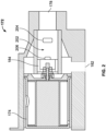
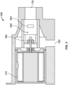
- the depicted control valve 172 in addition to the lubricant inlet 178, a lubricant outlet 182, and a valve element 184, further includes a flow chamber 202 disposed between the lubricant inlet 182 and the lubricant outlet184.
- the flow chamber 202 has a plurality of first flow orifices 204 and a plurality of second flow orifices 206.
- the first flow orifices 204 are disposed downstream of the lubricant inlet 178 and are configured such that lubricant may continuously flow through the first flow orifices 204 regardless of the valve element position.
- the second flow orifices 206 are disposed downstream of the first flow orifices 204 and are configured such that lubricant flow through the second flow orifices 206 is controlled based on the valve element position. Although only one first flow orifice 204 and only one second flow orifice 206 are visible in FIG. 2 , it will be appreciated that the flow chamber 202 preferably includes at least two first flow orifices 204 and at least two second flow orifices 206.
- valve element positions include a first end position, a plurality of throttle positions, and a second end position.
- first end position which is the position depicted in FIG. 3
- the valve element 184 prevents lubricant flow through the second flow orifices 206.
- throttle positions one of which is depicted in FIG. 4
- the valve element 184 throttles lubricant flow through the second flow orifices 206.
- second end position which is the position depicted in FIG. 2
- the valve element 206 allows non-throttled lubricant to flow though the second flow orifices 206.
- the first flow orifices 204 are configured such that, when the valve element 184 is in the first end position, lubricant flow from the lubricant inlet 178 to the lubricant outlet 182 is 60% of what lubricant flow is when the valve element 184 is in the second end position (e.g., 100%).
- the electromechanical valve actuator 174 is configured, upon a loss of electrical power thereto, to move the valve element 184 to a specific position.
- the specific position is the second end position, such that, upon a loss of electrical power, 100% lubricant flow through the control valve 172 is allowed.
- the first and second flow orifices 204, 206 are, at least in the depicted embodiment, are substantially rectangular in shape. However, other shapes could also be used.
- FIG. 5 is a plot 500 of lubricant flow through the control valve 172 versus compressor discharge pressure.
- the valve element 184 is in the second position, thus lubricant flow through the control valve 172 is initially 100%.
- the valve element 184 is rapidly moved to the first position, and thus lubricant flow through the control valve 172 drops very rapidly to 60%. This rapid drop, which occurs with little-to-no slope in the plot 500, may occur due to the above-described configuration of the control valve 172.
- valve element 184 is commanded to remain in the first position, and thus lubricant flow through the control valve 172 remains at 60%, until a predetermined compressor discharge pressure 502 is reached. At that point, the valve element 184 is commanded to move to the throttle positions and lubricant flow through the control valve 172 varies as a function of compressor discharge pressure. As FIG. 5 also depicts, lubricant flow through the valve element 184 will increase if compressor discharge pressure increases, until the valve element 184 is in the second position, at which point 504 lubricant flow through the control valve 172 is 100%. The variation in lubricant flow for compressor discharge pressures above the predetermined compressor discharge pressure 502 accommodates the optimal lubrication requirements of the fan reduction gearbox 118 and other components as engine load varies.
- the lubricant supply system described herein includes a control valve that does not use high-pressure, high-temperature air from the compressor and thereby does not increase the temperature of the lubricant flowing through the valve.
Landscapes
- Engineering & Computer Science (AREA)
- Mechanical Engineering (AREA)
- General Engineering & Computer Science (AREA)
- Chemical & Material Sciences (AREA)
- Combustion & Propulsion (AREA)
- Structures Of Non-Positive Displacement Pumps (AREA)
Applications Claiming Priority (2)
| Application Number | Priority Date | Filing Date | Title |
|---|---|---|---|
| IN202311014405 | 2023-03-03 | ||
| US18/301,784 US12000340B1 (en) | 2023-03-03 | 2023-04-17 | Gas turbine engine lubricant flow control system |
Publications (1)
| Publication Number | Publication Date |
|---|---|
| EP4424977A1 true EP4424977A1 (fr) | 2024-09-04 |
Family
ID=89897508
Family Applications (1)
| Application Number | Title | Priority Date | Filing Date |
|---|---|---|---|
| EP24156671.0A Pending EP4424977A1 (fr) | 2023-03-03 | 2024-02-08 | Système de commande de débit de lubrifiant de moteur à turbine à gaz |
Country Status (1)
| Country | Link |
|---|---|
| EP (1) | EP4424977A1 (fr) |
Citations (5)
| Publication number | Priority date | Publication date | Assignee | Title |
|---|---|---|---|---|
| US5012778A (en) * | 1990-09-21 | 1991-05-07 | Jacobs Brake Technology Corporation | Externally driven compression release retarder |
| CN201448443U (zh) * | 2009-07-24 | 2010-05-05 | 杨玉思 | 手、电、液三用y型多喷孔恒压调流阀 |
| US20180202557A1 (en) * | 2017-01-13 | 2018-07-19 | United Technologies Corporation | Multi-flowpath fluid control valve |
| CA3003802A1 (fr) * | 2017-07-25 | 2019-01-25 | Pratt & Whitney Canada Corp. | Soupape de decharge amortie utilisant des pistons doubles |
| EP4293202A1 (fr) * | 2022-06-14 | 2023-12-20 | Pratt & Whitney Canada Corp. | Soupape de purge avec séparation air-huile |
-
2024
- 2024-02-08 EP EP24156671.0A patent/EP4424977A1/fr active Pending
Patent Citations (5)
| Publication number | Priority date | Publication date | Assignee | Title |
|---|---|---|---|---|
| US5012778A (en) * | 1990-09-21 | 1991-05-07 | Jacobs Brake Technology Corporation | Externally driven compression release retarder |
| CN201448443U (zh) * | 2009-07-24 | 2010-05-05 | 杨玉思 | 手、电、液三用y型多喷孔恒压调流阀 |
| US20180202557A1 (en) * | 2017-01-13 | 2018-07-19 | United Technologies Corporation | Multi-flowpath fluid control valve |
| CA3003802A1 (fr) * | 2017-07-25 | 2019-01-25 | Pratt & Whitney Canada Corp. | Soupape de decharge amortie utilisant des pistons doubles |
| EP4293202A1 (fr) * | 2022-06-14 | 2023-12-20 | Pratt & Whitney Canada Corp. | Soupape de purge avec séparation air-huile |
Similar Documents
| Publication | Publication Date | Title |
|---|---|---|
| US6070404A (en) | Gaseous fuel compression and control method | |
| US7681402B2 (en) | Aeroengine oil tank fire protection system | |
| CA2729260C (fr) | Turbine a gaz libre avec vitesse du generateur au gaz corrigee a temperature constante | |
| EP3128153A1 (fr) | Unité de puissance auxiliaire avec rapport de vitesse variable | |
| EP2913500A1 (fr) | Dosage direct à l'aide d'une pompe à déplacement variable | |
| EP2772438A1 (fr) | Unités de puissance auxiliaire (APU) et procédés et systèmes pour l'activation et la désactivation d'un compresseur de charge dans celles-ci | |
| US20200141314A1 (en) | Gas turbine engine | |
| JP6027193B2 (ja) | 航空機のための低圧環境制御システムを有するギア式ターボファンエンジン | |
| EP3800340A1 (fr) | Système de carburant assisté par pompe électrique | |
| EP2982833B1 (fr) | Moteur a turbine a gaz | |
| CN109312665B (zh) | 用于燃气涡轮发动机的燃料输送系统和方法 | |
| CA2908652A1 (fr) | Protection contre le depassement de vitesse de moteur avec commande de poussee | |
| CN112302808A (zh) | 使用电机的压缩系统的主动稳定性控制 | |
| US20250270962A1 (en) | Variable transmission driven fuel pump for a gas turbine engine | |
| US10934889B2 (en) | System and method for supplying lubrication fluid to at least one member of an aircraft propulsion assembly | |
| US20260117677A1 (en) | Lubrication system for a turbine engine | |
| EP4424977A1 (fr) | Système de commande de débit de lubrifiant de moteur à turbine à gaz | |
| US12000340B1 (en) | Gas turbine engine lubricant flow control system | |
| US20200070081A1 (en) | Monitoring servo-valve filter elements | |
| EP0150729A2 (fr) | Méthode et dispositif pour améliorer la réponse d'une turbine à gaz à arbres multiples | |
| CA3170850A1 (fr) | Systeme et procede pour faire fonctionner un systeme multimoteur | |
| EP4438878B1 (fr) | Soupape de commande et démarreur de turbine à air combinés | |
| US12270337B1 (en) | Gas turbine engine oil flow control system | |
| EP2489859B1 (fr) | Turbine à gaz avec vitesse de rotation du générateur de gaz corrigée à température constante | |
| US20250250939A1 (en) | Shaft driven main pump bypass via electric pump |
Legal Events
| Date | Code | Title | Description |
|---|---|---|---|
| PUAI | Public reference made under article 153(3) epc to a published international application that has entered the european phase |
Free format text: ORIGINAL CODE: 0009012 |
|
| STAA | Information on the status of an ep patent application or granted ep patent |
Free format text: STATUS: THE APPLICATION HAS BEEN PUBLISHED |
|
| AK | Designated contracting states |
Kind code of ref document: A1 Designated state(s): AL AT BE BG CH CY CZ DE DK EE ES FI FR GB GR HR HU IE IS IT LI LT LU LV MC ME MK MT NL NO PL PT RO RS SE SI SK SM TR |
|
| P01 | Opt-out of the competence of the unified patent court (upc) registered |
Free format text: CASE NUMBER: APP_61769/2024 Effective date: 20241119 |
|
| STAA | Information on the status of an ep patent application or granted ep patent |
Free format text: STATUS: REQUEST FOR EXAMINATION WAS MADE |
|
| 17P | Request for examination filed |
Effective date: 20250226 |