EP2237009A1 - Micro-jauge de vide - Google Patents
Micro-jauge de vide Download PDFInfo
- Publication number
- EP2237009A1 EP2237009A1 EP09705829A EP09705829A EP2237009A1 EP 2237009 A1 EP2237009 A1 EP 2237009A1 EP 09705829 A EP09705829 A EP 09705829A EP 09705829 A EP09705829 A EP 09705829A EP 2237009 A1 EP2237009 A1 EP 2237009A1
- Authority
- EP
- European Patent Office
- Prior art keywords
- substrate
- floating structure
- vacuum gauge
- micro vacuum
- gauge according
- Prior art date
- Legal status (The legal status is an assumption and is not a legal conclusion. Google has not performed a legal analysis and makes no representation as to the accuracy of the status listed.)
- Withdrawn
Links
Images








Classifications
-
- G—PHYSICS
- G01—MEASURING; TESTING
- G01L—MEASURING FORCE, STRESS, TORQUE, WORK, MECHANICAL POWER, MECHANICAL EFFICIENCY, OR FLUID PRESSURE
- G01L21/00—Vacuum gauges
- G01L21/10—Vacuum gauges by measuring variations in the heat conductivity of the medium, the pressure of which is to be measured
- G01L21/12—Vacuum gauges by measuring variations in the heat conductivity of the medium, the pressure of which is to be measured measuring changes in electric resistance of measuring members, e.g. of filaments; Vacuum gauges of the Pirani type
Definitions
- the present invention relates to a micro vacuum gauge that measures a pressure inside a vacuum vessel where a pressure is reduced to be lower than an atmospheric pressure.
- the present invention relates to a micro vacuum gauge that measures a low-pressure region, which is necessary for a device utilizing an MEMS (Micro-Electro-Mechanical Systems) technique.
- MEMS Micro-Electro-Mechanical Systems
- a thermal infrared sensor heat dissipation from a sensor structure largely affects performance, and thus, it is desired to reduce heat conduction through the atmosphere as much as possible.
- some of acceleration sensors and angler speed sensors are, for a specific purpose, required to be operated in a vacuum environment in order to reduce damping by the atmosphere (mechanical resistance of the air).
- vacuum sealing is performed for the purpose of increasing properties of a resonator, which is a vibrating device, or for the purpose of preventing sticking of a device involving mechanical contact such as a switch (sticking of a movable structure to a substrate).
- Non-Patent Document 1 A.W. van Herwaarden and P.M. Sarro, J.Vac. Sci. Technol., Vol. A5, No. 4, pp. 2454-2457, 1987 .
- a temperature of the floating structure 92 rises.
- the rise in temperature is decided by a power supplied to the heater 93, and a heat loss (transmitted heat quantity) flowing from the floating structure 92 to the semiconductor substrate 91 serving as a heat sink and peripheral structures not shown.
- This heat loss is due to three factors of heat conduction through gas surrounding the floating structure 92, heat conduction through the supporting structure 98, and heat radiation from the floating structure 92.
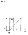
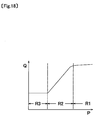
- the region R2 is a region in which since the average free path of the gas is longer than the length of the hollow space S, the heat conduction through the gas is proportional to the pressure (molecular density) of the gas, and with reduction in pressure, the heat loss is reduced.
- the region R3 is a low-pressure region with the heat loss Q at a lowest level, in which the heat loss Q does not depend on the pressure P of the gas, and the heat loss by the heat conduction through the supporting structure 98 and the heat loss by the heat emission (heat radiation) from the floating structure 92 are added.
- the conventional micro vacuum gauge 90 by the heat conduction method cannot measure a sufficiently low pressure.
- the conventional micro vacuum gauge 90 by the heat conduction method cannot measure pressure change inside the package of the thermal infrared sensor, which is vacuum-sealed to be used. That is, the heat loss mechanism of the micro vacuum gauge by the heat conduction method is the same as the thermal loss mechanism of the thermal infrared sensor, which is vacuum-sealed to be used, and a pressure region in which sensitivity of the thermal infrared sensor depends on a pressure of gas inside the sealed package almost coincides with the region R2.
- the present invention has been devised to solve the above-described problem, and an object thereof is to expand a measurable pressure range to the lower pressure side so as to be able to conduct a reliability test and self-diagnosis of a device by a micro vacuum gauge by a heat conduction method, which is integrated in an MEMS device or the like, to increase a measurement lower limit. Furthermore, another object thereof is to expand a measurement range of an extremely compact, micro vacuum gauge by a heat conduction method capable of pressure measurement in a minute space, thereby expanding an application field of the micro vacuum gauge.
- a micro vacuum gauge to achieve the above-described objects is a micro vacuum gauge including a substrate, a floating structure that is held above the substrate by a supporting structure extending from the substrate in a state where the floating structure is thermally isolated from the substrate, a heat generator that is arranged in the floating structure to generate heat, and a temperature sensor that is arranged in the floating structure to measure a difference in temperature between the substrate and the floating structure, wherein at least on a surface of the floating structure, a second member having a lower emissivity than a first member surrounding the heat generator and the temperature sensor is formed by being joined to the first member.
- the micro vacuum gauge according to the present invention has a feature in that the second member has a higher reflectance than the first member.
- the micro vacuum gauge according to present invention has a feature in that the first member is made of silicon dioxide or silicon nitride, and the second member is made of aluminum, titanium, gold, tungsten or platinum.
- the micro vacuum gauge according to present invention has a feature in that an upper surface of the substrate is formed flatly, and the floating structure is held by the supporting structure so as to be elevated upward from the upper surface of the substrate.
- a micro vacuum gauge is a micro vacuum gauge including a substrate, a floating structure that is held above the substrate by a supporting structure extending from the substrate in a state where the floating structure is thermally isolated from the substrate, a heat generator that is arranged in the floating structure to generate heat, and a temperature sensor that is arranged in the floating structure to measure a difference in temperature between the substrate and the floating structure, wherein in the substrate, a member that reflects infrared rays to decrease energy loss by radiation from the floating structure is formed.
- the micro vacuum gauge according to present invention has a feature in that a depressed portion is formed in an upper surface of the substrate, and the floating structure is held above the depressed portion by the supporting structure, while the member reflecting the infrared rays is formed so as to extend from the substrate and cover the upper side of the floating structure.
- the micro vacuum gauge according to present invention has a feature in that an upper surface of the substrate is formed flatly, and the floating structure is held by the supporting structure so as to be elevated upward from the upper surface of the substrate, while the member reflecting the infrared rays is formed so as to extend from the substrate and cover the upper side of the floating structure.
- a micro vacuum gauge is a micro vacuum gauge including a substrate, a floating structure that is held above the substrate by a supporting structure extending from the substrate in a state where the floating structure is thermally isolated from the substrate, a heat generator that is arranged in the floating structure to generate heat, and a temperature sensor that is arranged in the floating structure to measure a difference in temperature between the substrate and the floating structure, wherein on a package substrate on which the substrate is mounted, a member that reflects infrared rays to decrease energy loss by radiation from the floating structure is formed.
- the micro vacuum gauge according to present invention has a feature in that a hollow space is formed under the floating structure so as to penetrate the substrate vertically, and on an inner surface of the substrate surrounding the hollow space, the member reflecting the infrared rays is formed.
- the second member having a lower emissivity than the first member surrounding the heat generator and the temperature sensor is formed at least on a surface of the floating structure, the heat loss by heat radiation from the floating structure is smaller than that of the conventional micro vacuum gauge in which the whole floating structure is made of the same material as that of the first member.
- a measurable pressure range in the micro vacuum gauge can be expanded to the lower pressure side.
- the emissivity of the second member can be made lower than that of the first member.
- the micro vacuum gauge of the present invention since the member that reflects the infrared rays to decrease the energy loss by the radiation from the floating structure is formed in the substrate, the energy radiated on the side where the aforementioned member is formed in the energy radiated from the floating structure is decreased, thereby making the heat loss smaller.
- the measurable pressure range in the micro vacuum gauge can be expanded to the lower pressure side.
- the member reflecting the infrared rays is formed so as to extend from the substrate and cover the upper side of the floating structure, the member can be easily formed. Moreover, the addition of the member can also be easily performed.
- the micro vacuum gauge of the present invention since the upper surface of the substrate is formed flatly, and the floating structure is held by the supporting structure so as to be elevated upward from the upper surface of the substrate, while the member reflecting the infrared rays is formed on the upper surface of the substrate, the member can be easily formed. Moreover, the addition of the member can also be easily performed.
- the member that reflects infrared rays to decrease the energy loss by radiation from the floating structure is formed, the member can be easily formed. Moreover, the addition of the member can also be easily performed.
- the micro vacuum gauge of the present invention since the hollow space is formed under the floating structure so as to penetrate the substrate vertically, and on the inner surface of the substrate surrounding the hollow space, the member reflecting the infrared rays is formed, the effect of decreasing the energy loss by the radiation from the floating structure can be further enhanced.
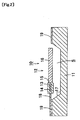
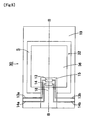
- the micro vacuum gauge 10 is a micro vacuum gauge by a heat conduction method, including a semiconductor substrate (substrate) 11, and a floating structure 12 thermally isolated from the semiconductor substrate 11, as shown in Figs. 1 and 2 .
- a heater (heat generator) 13 and a temperature sensor 14 are arranged in the floating structure 12.
- the floating structure 12 is made up of a first member 15 surrounding the heater 13 and the temperature sensor 14, and a second member 16 having a low emissivity than the first member 15.
- a depressed portion 17 is formed in an upper surface of the semiconductor substrate 11 so that the floating structure 12 is held above the depressed portion 17 by a supporting structure 18, and a hollow space (air gap) S is provided between the semiconductor substrate 11 and the floating structure 12 to separate space.
- a resistor made of polysilicon, or the like can be used for the heater 13, a resistor made of polysilicon, or the like.
- a resistance bolometer, a diode, a thermoelectric device (thermocouple or thermopile) or the like can be used as the temperature sensor 14.
- a difference in temperature between the semiconductor substrate 11 and the floating structure 12 needs to be measured, in the others than the thermoelectric device from which output corresponding to the difference in temperature can be obtained, it is preferable to dispose a reference temperature sensor not shown on the semiconductor substrate 11.
- heater wirings 13a, 13b to the heater 13 are connected heater wirings 13a, 13b, and to the temperature sensor 14 are temperature sensor wirings 14a, 14b.
- the thermopile which is one of the thermoelectric devices, is used as the temperature sensor 14 there may arise a necessity that a number of wirings are formed between the floating structure 12 and a region where the semiconductor substrate 11 serves as a heat sink.
- the micro vacuum gauge 10 has the floating structure 12 with the hollow space S interposed between the semiconductor substrate 11 and itself, as in the aforementioned conventional micro vacuum gauge 90 shown in Figs. 16 and 17 .
- structures other than the floating structure 12 are similar to those of the conventional micro vacuum gauge 90.
- a planar size (in top view) of the first member 15 in the floating structure 12 is a minimum size necessary for arranging the heater 13 and the temperature sensor 14, and the other region, in which the floating structure 92 in the conventional micro vacuum gauge 90 occupies, is made of the high-reflectance thin film 16, which is the second member having a lower emissivity than the first member 15 and the floating structure 92.
- the high-reflectance thin film 16 is formed of aluminum used as a wiring metal material in a semiconductor manufacturing process. This allows the semiconductor manufacturing process to be adapted when the micro vacuum gauge 10 is manufactured, which makes easy manufacturing possible.
- the material is not limited to aluminum, but any material including metal such as titanium and gold that has a low emissivity may be used.
- the first member 15 is normally limited to a silicon dioxide film SiO 2 , a silicon nitride film SiN, a resultant from adding another element on a basis of those, or a resultant from slightly changing their chemical compositions.
- the high-reflectance thin film 16 only needs to have a higher reflectance than these materials making the first member 15.
- the micro vacuum gauge 10 measures a heat loss from the first member 15 with the heater 13 and the temperature sensor 14 arranged therein and the high-reflectance thin film 16, as change in temperature or change in supplied power.
- a case where a constant power is supplied to the heater 13 is described.
- Characteristics of the conventional micro vacuum gauge 90 are indicated by a dashed line in Fig. 3 .
- the heat loss by the radiation from the portion where the conventional floating structure 92 is replaced by the high-reflectance thin film 16 is decreased, by which the heat loss resulting from adding the heat loss by the heat conduction through the supporting structure 18, and the heat loss by the heat radiation from the first member 15 and the high-reflectance thin film 16 is made smaller by ⁇ Q.
- the heat loss by the heat conduction through the conventional supporting structure 98 is made negligibly small as compared with the heat loss by the heat radiation from the floating structure 92
- most of the conventional floating structure 92 is replaced by the high-reflectance thin film 16
- the heat loss by the heat conduction through the supporting structure 18 is made negligibly small as compared with the heat loss by the heat radiation from the first member 15 and the high-reflectance thin film 16, that is, when a lower limit of the measurable region (region R2) in the conventional and present embodiments is decided by the heat radiation
- the heat loss in the region R3 can be made smaller almost by a ratio between the emissivity of the conventional floating structure 92 and the emissivity of the high-reflectance thin film 16.
- the use of the micro vacuum gauge 10 of the present invention moves the pressure at the time of shift from the region R2 to the region R3 to the lower pressure side by ⁇ P equivalent to the decrease in heat loss by the radiation, so that a measurable pressure range is expanded to the lower pressure side.
- a measurable pressure lower limit becomes, for example, about 1 ⁇ 10 -2 Pa.
- the number of the supporting structures 18 is one, and the supporting structure 18 has a rectangular flat plate-like structure, the number of the supporting structures 18 may be plural, and it may have a complex shape such as meander geometry. Moreover, the supporting structure 18 may be structured to be connected not only to the first member 15 but also the high-reflectance thin film 16.
- a micro vacuum gauge 20 according to a second embodiment of the present invention is described with reference to the drawings.
- a floating structure 22 is held by the supporting structure 18 so as to almost cover the upper side of the depressed portion 17, a first member 25 of the same planar size (in top view) as that of the floating structure 22 is formed, and high-reflectance films 26a, 26b as the second members are formed across the whole of an upper surface and a lower surface of this first member 25.
- the first member 25 occupies the region which the first member 15 and the high-reflectance film 16 in the aforementioned micro vacuum gauge 10 occupy.
- the micro vacuum gauge 20 has a structure in which the high-reflectance thin films 26a, 26b are added to an upper surface and a lower surface of the floating structure 92 of the conventional micro vacuum gauge 90 shown in Figs. 16 and 17 to be formed.
- the micro vacuum gauge 20 Since reflection is decided by a material and a structure of an outmost surface layer, as in the aforementioned micro vacuum gauge 10, the micro vacuum gauge 20 also reduces the heat loss in the region R3 by the decrease of the radiation from the high-reflectance films 26a, 26b, so that the measurable range can be expanded to the lower pressure side. While in the micro vacuum gauge 20, the high-reflectance thin films 26a, 26b are formed across the whole surfaces of both the upper and lower surfaces of the first member 25 so as to cover the whole upper and lower surfaces of the floating structure 22, they may not be formed across the whole surfaces, but may be formed only on one of the upper surface and the lower surface.
- micro vacuum gauge 30 As shown in Figs. 5 and 6 , has the same structure as that of the micro vacuum gauge 10 except that the high-reflectance thin film 16 of the micro vacuum gauge 10 shown in Figs. 1 and 2 is replaced by a high-transmittance thin film 36.
- a material with a transmittance close to 1 has a very small emissivity.
- the measurable pressure range can be expanded to the lower pressure side.
- a temperature region of an environment in which the micro vacuum gauge operates is 200°C to 300°C at the highest, and radiated light is light in an infrared region.
- the material used for the high-transmittance thin film 36 is not limited to this, but a similar effect can be obtained as long as a material having a high transmittance to infrared rays that a black body near an operation temperature radiates is used.
- the micro vacuum gauge 30 is not limited to the structure and the shape shown in Figs. 5 and 6 , but the modifications in design, which have been described as to the micro vacuum gauge 10, can be made as needed.
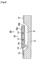
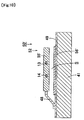
- micro vacuum gauge 40 does not hold the floating structure 12 at almost the same height as the upper surface of the semiconductor substrate 11 as in the micro vacuum gauge 10, but holds the floating structure 42 by a supporting structure 48 in a state where the floating structure 42 is elevated upward from an upper surface of a semiconductor substrate 41. Thus, a depressed portion does not need to be formed in the upper surface of the semiconductor substrate 41.
- this micro vacuum gauge 40 is also similar to that of the micro vacuum gauge 10, and the heat loss in the region R3 is reduced by the decrease in radiation from the high-reflectance thin film 16, and the measurable range can be expanded to the lower pressure side.
- the micro vacuum gauge 40 is not limited to the structure and the shape shown in Figs. 7 and 8 , but the modifications in design, which have been described as to the micro vacuum gauge 10, can be made as needed.
- the micro vacuum gauge 50 has a structure in which a high-reflectance thin film 56 is added on the lower surface of the semiconductor substrate 11 to the conventional micro vacuum gauge 90, as shown in Fig. 9 .
- the depressed portion 17 is formed in the upper surface of the semiconductor substrate 11. It is difficult to form the high-reflectance thin film on an upper surface of this depressed portion 17. Consequently, the high-reflectance thin film 56 is additionally formed on the back surface of the semiconductor substrate 11.
- the floating structures 52, 52' radiate the infrared rays both upward and downward.
- the micro vacuum gauges 50, 50' have an effect of decreasing only the energy radiated downward in the energy radiated from the floating structures 52, 52', and the effect is almost half the effect of the micro vacuum gauge 20.
- This embodiment can also be used in combination with another embodiment to complement the effect of the micro vacuum gauge.
- a micro vacuum gauge 60' according to a modification of the sixth embodiment of the present invention is described.
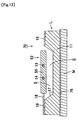
- a high-reflectance thin film 66' covering the upper side of the floating structure 52' at a space is formed on the upper surface of the insulating film 49 formed on the semiconductor substrate 41.
- the high-reflectance thin film 66' is formed so as to overlap the floating structure 52' in top view.
- the micro vacuum gauge 60' has the effect of decreasing only the energy radiated upward in the energy radiated from the floating structure 52', which is an upside-down effect of the micro vacuum gauge 50'.
- This embodiment can be realized in a form of being added to another embodiment, and the effect of the micro vacuum gauge can be further enhanced.
- a micro vacuum gauge 70 according to a seventh embodiment of the present invention is described.
- a micro vacuum gauge element L made up of the semiconductor substrate 11, the floating structure 52, the supporting structure 18 and the like has the same structure as the conventional one (exactly the same as the aforementioned conventional micro vacuum gauge 90)
- a high-reflectance thin film 76 is formed on a joint surface with the micro vacuum gauge element L of a package substrate M, on which the micro vacuum gauge element L is mounted.
- the high-reflectance thin film 76 is formed so as to overlap the floating structure 52 in top view.
- the micro vacuum gauge 70 similarly to the micro vacuum gauge 50, has the effect of decreasing only the energy radiated downward in the energy radiated from the floating structure 52.
- This embodiment can be realized in a form of being added to another embodiment, and the effect of the micro vacuum gauge can be further enhanced.
- a micro vacuum gauge 70' according to a modification of the seventh embodiment of the present invention is described.
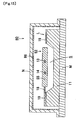
- a hollow space S' penetrating vertically in a semiconductor substrate 71 of the micro vacuum gauge element L' is formed, and a floating structure 72 is supported by a supporting structure 78 in a form of both-end support.
- the high-reflectance thin film 76 is formed on a joint surface with the micro vacuum gauge element L' of the package substrate M, on which the micro vacuum gauge element L' is mounted.
- the hollow space S' is formed so as to penetrate the semiconductor substrate 71, it is common to perform anisotropic etching from a back surface of the semiconductor substrate 71.
- the hollow space S' has a shape opened in a lower surface. This allows the high-reflectance thin film 76' to be formed on an inner surface of the semiconductor substrate 71 surrounding the hollow space S', which can further enhance the effect.
- the micro vacuum gauge according to the present invention since in the micro vacuum gauge according to the present invention, the measurable range on the lower pressure side is expanded as compared with the conventional micro vacuum gauge, the measurement of a pressure lower than a pressure level required as an upper limit pressure in a thermal infrared sensor or the like is enabled. Since the micro vacuum gauge according to the present invention can be manufactured by the same technique as the manufacturing process for manufacturing the thermal infrared sensor, it is integrated in the thermal infrared sensor so that it can be applied to analysis of influence of deterioration in vacuum degree in a reliability test, or self-diagnosis of a product used in a real field.
Landscapes
- Physics & Mathematics (AREA)
- General Physics & Mathematics (AREA)
- Measuring Fluid Pressure (AREA)
Applications Claiming Priority (2)
| Application Number | Priority Date | Filing Date | Title |
|---|---|---|---|
| JP2008021826 | 2008-01-31 | ||
| PCT/JP2009/051533 WO2009096504A1 (fr) | 2008-01-31 | 2009-01-30 | Micro-jauge de vide |
Publications (2)
| Publication Number | Publication Date |
|---|---|
| EP2237009A1 true EP2237009A1 (fr) | 2010-10-06 |
| EP2237009A4 EP2237009A4 (fr) | 2013-01-16 |
Family
ID=40912847
Family Applications (1)
| Application Number | Title | Priority Date | Filing Date |
|---|---|---|---|
| EP09705829A Withdrawn EP2237009A4 (fr) | 2008-01-31 | 2009-01-30 | Micro-jauge de vide |
Country Status (4)
| Country | Link |
|---|---|
| US (1) | US8258509B2 (fr) |
| EP (1) | EP2237009A4 (fr) |
| JP (1) | JP5002861B2 (fr) |
| WO (1) | WO2009096504A1 (fr) |
Families Citing this family (10)
| Publication number | Priority date | Publication date | Assignee | Title |
|---|---|---|---|---|
| NL2004419C2 (en) * | 2010-03-17 | 2011-09-20 | Stichting Materials Innovation Inst M2I | Device, system and method for the measurement of a vapor transmission rate through a film of permeable material. |
| CN102923644B (zh) * | 2012-11-20 | 2015-05-13 | 中国科学院上海微系统与信息技术研究所 | 一种三维真空传感器及其制备方法 |
| US10677656B2 (en) | 2012-12-31 | 2020-06-09 | Flir Systems, Inc. | Devices and methods for infrared reference pixels |
| US9606016B2 (en) * | 2012-12-31 | 2017-03-28 | Flir Systems, Inc. | Devices and methods for determining vacuum pressure levels |
| US9335231B2 (en) | 2014-03-25 | 2016-05-10 | Mks Instruments, Inc. | Micro-Pirani vacuum gauges |
| JP6261463B2 (ja) * | 2014-06-27 | 2018-01-17 | 東京エレクトロン株式会社 | 圧力測定装置および圧力測定方法 |
| JP6293588B2 (ja) * | 2014-06-27 | 2018-03-14 | 東京エレクトロン株式会社 | 圧力センサおよび圧力センサの製造方法 |
| US10753816B2 (en) * | 2017-06-15 | 2020-08-25 | Kevin Kornelsen | Calibration-less micro-fabricated vacuum gauge devices and method for measuring pressure |
| CN113588159B (zh) * | 2021-08-23 | 2023-05-23 | 青岛芯笙微纳电子科技有限公司 | 一种宽量程的mems真空计及其制作方法 |
| CH722070A1 (de) * | 2024-08-27 | 2026-03-13 | Inficon ag | Mems pirani sensorvorrichtung und verfahren zum betrieb einer solchen vorrichtung |
Family Cites Families (11)
| Publication number | Priority date | Publication date | Assignee | Title |
|---|---|---|---|---|
| US5374123A (en) * | 1992-05-20 | 1994-12-20 | Goldstar Co., Ltd. | Thermal comfort sensing device |
| US5347869A (en) * | 1993-03-25 | 1994-09-20 | Opto Tech Corporation | Structure of micro-pirani sensor |
| US5597957A (en) * | 1993-12-23 | 1997-01-28 | Heimann Optoelectronics Gmbh | Microvacuum sensor having an expanded sensitivity range |
| US5557972A (en) * | 1994-09-13 | 1996-09-24 | Teledyne Industries, Inc. | Miniature silicon based thermal vacuum sensor and method of measuring vacuum pressures |
| JPH08166269A (ja) * | 1994-12-16 | 1996-06-25 | Tokyo Gas Co Ltd | 熱線式フローセンサ |
| JPH0989617A (ja) * | 1995-09-19 | 1997-04-04 | Tokyo Gas Co Ltd | 半導体発熱装置およびその製造方法 |
| EP1300664A4 (fr) * | 2000-07-13 | 2007-05-30 | Mitsubishi Electric Corp | Capteur de pression |
| JP2003323072A (ja) * | 2002-04-30 | 2003-11-14 | Brother Ind Ltd | 定着器及び画像形成装置 |
| US20030209669A1 (en) * | 2002-05-09 | 2003-11-13 | Chou Bruce C. S. | Miniaturized infrared gas analyzing apparatus |
| JP2006153782A (ja) * | 2004-11-30 | 2006-06-15 | Mitsuteru Kimura | 多孔蓋を有した気体センシングデバイス |
| JP2006323072A (ja) | 2005-05-18 | 2006-11-30 | Sumitomo Electric Ind Ltd | 光ファイバ心線 |
-
2009
- 2009-01-30 JP JP2009551589A patent/JP5002861B2/ja not_active Expired - Fee Related
- 2009-01-30 EP EP09705829A patent/EP2237009A4/fr not_active Withdrawn
- 2009-01-30 WO PCT/JP2009/051533 patent/WO2009096504A1/fr not_active Ceased
- 2009-01-30 US US12/865,139 patent/US8258509B2/en not_active Expired - Fee Related
Also Published As
| Publication number | Publication date |
|---|---|
| JP5002861B2 (ja) | 2012-08-15 |
| US20100327279A1 (en) | 2010-12-30 |
| US8258509B2 (en) | 2012-09-04 |
| EP2237009A4 (fr) | 2013-01-16 |
| WO2009096504A1 (fr) | 2009-08-06 |
| JPWO2009096504A1 (ja) | 2011-05-26 |
Similar Documents
| Publication | Publication Date | Title |
|---|---|---|
| US8258509B2 (en) | Micro vacuum gauge | |
| Zhang et al. | A micro-Pirani vacuum gauge based on micro-hotplate technology | |
| US20190331514A1 (en) | A thermal fluid flow sensor | |
| US8449177B2 (en) | Vacuum sensor | |
| US6300554B1 (en) | Method of fabricating thermoelectric sensor and thermoelectric sensor device | |
| US9851253B2 (en) | Infrared thermal sensor with good SNR | |
| US8853632B2 (en) | Planar thermopile infrared microsensor | |
| CN110431386A (zh) | 单膜式流量压力感测装置 | |
| US11067422B2 (en) | Thermal fluid flow sensor | |
| JP5001007B2 (ja) | 最適化された表面を活用する赤外線センサー | |
| GB2574302A (en) | Thermal fluid flow sensor | |
| US20150177070A1 (en) | Infrared thermal sensor with beams having different widths | |
| CN108885137A (zh) | 一种ir检测器阵列设备 | |
| CN111742201A (zh) | 红外设备 | |
| NL2003838C2 (en) | Thermogravimetric device. | |
| JP5769043B2 (ja) | 電気素子、集積素子、電子回路及び温度較正装置 | |
| JP2008145133A (ja) | 放射温度計 | |
| Yoo et al. | Fabrication, characterization and application of a microelectromechanical system (MEMS) thermopile for non-dispersive infrared gas sensors | |
| RU2251087C2 (ru) | Емкостной датчик давления | |
| JP2012078245A (ja) | 電気素子、集積素子及び電子回路 | |
| Sisto et al. | Pressure sensing in vacuum hermetic micropackaging for MOEMS-MEMS | |
| Hildenbrand et al. | Fast transient temperature operating micromachined emitter for mid-infrared optical gas sensing systems: design, fabrication, characterization and optimization | |
| Wang et al. | A CMOS-compatible temperature sensor based on the gaseous thermal conduction dependent on temperature | |
| JP5590454B2 (ja) | 電気素子、集積素子及び電子回路 | |
| JP5761589B2 (ja) | 電気素子、集積素子、電子回路及び温度較正装置 |
Legal Events
| Date | Code | Title | Description |
|---|---|---|---|
| PUAI | Public reference made under article 153(3) epc to a published international application that has entered the european phase |
Free format text: ORIGINAL CODE: 0009012 |
|
| 17P | Request for examination filed |
Effective date: 20100803 |
|
| AK | Designated contracting states |
Kind code of ref document: A1 Designated state(s): AT BE BG CH CY CZ DE DK EE ES FI FR GB GR HR HU IE IS IT LI LT LU LV MC MK MT NL NO PL PT RO SE SI SK TR |
|
| AX | Request for extension of the european patent |
Extension state: AL BA RS |
|
| DAX | Request for extension of the european patent (deleted) | ||
| A4 | Supplementary search report drawn up and despatched |
Effective date: 20121218 |
|
| RIC1 | Information provided on ipc code assigned before grant |
Ipc: G01L 21/12 20060101AFI20121212BHEP |
|
| STAA | Information on the status of an ep patent application or granted ep patent |
Free format text: STATUS: THE APPLICATION IS DEEMED TO BE WITHDRAWN |
|
| 18D | Application deemed to be withdrawn |
Effective date: 20140801 |