EP2237046A2 - Probenverarbeitungsvorrichtung und Probenverarbeitungsverfahren - Google Patents
Probenverarbeitungsvorrichtung und Probenverarbeitungsverfahren Download PDFInfo
- Publication number
- EP2237046A2 EP2237046A2 EP20100157502 EP10157502A EP2237046A2 EP 2237046 A2 EP2237046 A2 EP 2237046A2 EP 20100157502 EP20100157502 EP 20100157502 EP 10157502 A EP10157502 A EP 10157502A EP 2237046 A2 EP2237046 A2 EP 2237046A2
- Authority
- EP
- European Patent Office
- Prior art keywords
- sample
- section
- rack
- container
- returning
- Prior art date
- Legal status (The legal status is an assumption and is not a legal conclusion. Google has not performed a legal analysis and makes no representation as to the accuracy of the status listed.)
- Withdrawn
Links
Images











Classifications
-
- G—PHYSICS
- G01—MEASURING; TESTING
- G01N—INVESTIGATING OR ANALYSING MATERIALS BY DETERMINING THEIR CHEMICAL OR PHYSICAL PROPERTIES
- G01N35/00—Automatic analysis not limited to methods or materials provided for in any single one of groups G01N1/00 - G01N33/00; Handling materials therefor
- G01N35/02—Automatic analysis not limited to methods or materials provided for in any single one of groups G01N1/00 - G01N33/00; Handling materials therefor using a plurality of sample containers moved by a conveyor system past one or more treatment or analysis stations
-
- G—PHYSICS
- G01—MEASURING; TESTING
- G01N—INVESTIGATING OR ANALYSING MATERIALS BY DETERMINING THEIR CHEMICAL OR PHYSICAL PROPERTIES
- G01N35/00—Automatic analysis not limited to methods or materials provided for in any single one of groups G01N1/00 - G01N33/00; Handling materials therefor
- G01N35/00584—Control arrangements for automatic analysers
- G01N35/0092—Scheduling
-
- G—PHYSICS
- G01—MEASURING; TESTING
- G01N—INVESTIGATING OR ANALYSING MATERIALS BY DETERMINING THEIR CHEMICAL OR PHYSICAL PROPERTIES
- G01N35/00—Automatic analysis not limited to methods or materials provided for in any single one of groups G01N1/00 - G01N33/00; Handling materials therefor
- G01N35/02—Automatic analysis not limited to methods or materials provided for in any single one of groups G01N1/00 - G01N33/00; Handling materials therefor using a plurality of sample containers moved by a conveyor system past one or more treatment or analysis stations
- G01N35/026—Automatic analysis not limited to methods or materials provided for in any single one of groups G01N1/00 - G01N33/00; Handling materials therefor using a plurality of sample containers moved by a conveyor system past one or more treatment or analysis stations having blocks or racks of reaction cells or cuvettes
-
- G—PHYSICS
- G01—MEASURING; TESTING
- G01N—INVESTIGATING OR ANALYSING MATERIALS BY DETERMINING THEIR CHEMICAL OR PHYSICAL PROPERTIES
- G01N35/00—Automatic analysis not limited to methods or materials provided for in any single one of groups G01N1/00 - G01N33/00; Handling materials therefor
- G01N35/02—Automatic analysis not limited to methods or materials provided for in any single one of groups G01N1/00 - G01N33/00; Handling materials therefor using a plurality of sample containers moved by a conveyor system past one or more treatment or analysis stations
- G01N35/04—Details of the conveyor system
- G01N2035/0401—Sample carriers, cuvettes or reaction vessels
- G01N2035/0406—Individual bottles or tubes
- G01N2035/041—Individual bottles or tubes lifting items out of a rack for access
Definitions
- the present invention relates to a sample processing apparatus and a sample processing method, which transports a sample rack holding a plurality of sample containers, and processes the samples contained in the sample containers.
- sample processing apparatuses are configured to be provided with a transport section for transporting a sample rack holding plural sample containers, aspirates the samples from the sample containers held by the sample rack transported by the transport section, and processes the samples.
- Japanese Patent Publication No. H5-072212 discloses an automatic analyzing apparatus which includes a reaction disk in which plural reaction containers are provided on a concentric circumference, and a reagent disk in which plural reagent bottles containing various reagents are provided on a concentric circle.
- a sample dispensing probe, a reagent dispensing probe, a stirring apparatus, a cleaning apparatus, a light source, and a multi-wave-length photometer are disposed on the peripheral of the reaction disk and the reagent disk.
- a rack transport apparatus is provided on a rotation circumference of the sample dispensing probe and along a tangential direction of the reaction disk, and a rack number reading apparatus and a sample ID reading apparatus are disposed along a transport line of the rack transport apparatus.
- the sample rack holding the sample container containing sample is transported on the transport line by the rack transport apparatus.
- the rack number of the sample rack is read by the rack number reading apparatus.
- the ID number of the sample container held by the sample rack is read.
- the sample rack is transported by the rack transport apparatus until the sample container held by the sample rack reaches the position under the sample dispensing probe, and a predetermined amount of the sample in the sample container is dispensed into a reaction container by the sample dispensing probe.
- the sample rack is transported by the rack transport apparatus such that the next sample container reaches the position under the sample dispensing probe, and the dispensing of the sample is carried out by the sample dispensing probe.
- a sample rack can be transported to a processing position and another sample container held by a sample rack can be subjected to another process. Therefore, independently of a positional relationship with the sample container containing the sample as a processing subject in the sample rack, it is possible to perform another process on another sample container.
- the unloading and returning of the sample with respect to the sample rack can be performed in parallel with each other, so that the sample processing capability of the sample processing apparatus can be further increased.
- the sample processing apparatus is provided with a first measurement unit, a second measurement unit, a sample transport unit, and an information processing unit.
- the sample processing apparatus transports a sample rack holding plural sample containers by the sample transport unit, reads a sample bar-code while the sample container is taking in sample measuring of one measurement unit, or transports the sample rack by the sample transport unit for taking in or returning by the other measurement unit of the sample container.
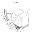
- Figs. 1A and 1B are perspective views illustrating the entire configuration of the sample processing apparatus according to the embodiment.
- the sample processing apparatus 1 according to the embodiment is a multiple blood cell analyzing apparatus which detects blood cells, such as the white blood cells, the red blood cells, and platelets which are included in a blood sample, and counts each blood cell.
- the sample processing apparatus 1 is provided with a first measurement unit 2, a second measurement unit 3, a sample transport unit 4, and an information processing unit 5 which can control the first measurement unit 2, the second measurement unit 3, and the sample transport unit 4.
- the sample transport unit 4 is disposed on a front side surface of the first measurement unit 2 and the second measurement unit 3.
- Fig. 2 is a perspective view illustrating an appearance of the sample container containing the sample.
- the sample container T is formed in a tubular shape, and the upper end is opened.
- a blood sample gathered from a patient is contained in the sample container, and the opening on the upper end is sealed by a cap section CP.
- the sample container T is made of a transparent glass or a transparent synthetic resin, so that the blood sample therein is visible.
- the bar-code label BL1 is attached to the side surface of the sample container T.
- a bar-code indicating the sample ID is printed on the bar-code label BL1.
- Fig. 3 is a perspective view illustrating an appearance of the sample rack holding the plural sample containers. As shown in Fig.
- the sample rack L can arrange and hold 10 sample containers T. Each sample container T is held in a vertical state (upright state) in the sample rack L.
- a bar-code label BL2 is attached on the side surface of the sample rack L.
- a bar-code indicating the rack ID is printed on the bar-code label BL2.
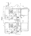
- Fig. 4 is a block diagram illustrating the configuration of the measurement unit. As shown in Fig. 4 , the first measurement unit 2 is disposed on the upstream side (right side in the paper) in a transport direction (X direction) of the sample of the sample transport unit 4. The second measurement unit 3 is disposed on the downstream side (left side in the paper) in the transport direction (X direction).
- the first measurement unit 2 includes a sample aspirating section 21 which aspirates blood as the sample from the sample container (blood collection tube) T, a sample preparing section 22 which prepares a measuring sample to be used in measuring of blood components, such as blood cells, from the blood aspirated by the sample aspirating section 21, and a detecting section 23 which detects (measures) the blood cells from the measuring sample prepared by the sample preparing section 22.
- the first measurement unit 2 further includes a take-in port 24 (see Figs.
- an aspiration tube is provided at the tip end of the sample aspirating section 21.
- the sample aspirating section 21 is configured to be able to move vertically and downward, so that the aspiration tube penetrates into the cap section CP of the sample container T transported to the aspirating position so as to aspirate the blood in the sample container.
- the sample preparing section 22 is provided with plural reaction chambers.
- the sample preparing section 22 is connected to a reagent container, and can supply a reagent, such as a staining reagent, a hemolytic agent, or a diluting fluid, to the reaction chamber.
- the sample preparing section 22 is also connected to the aspiration tube of the sample aspirating section 21, and can supply the blood sample aspirated by the aspiration tube to the reaction chamber.
- the sample preparing section 22 mixes and stirs the sample in the reaction chamber with the reagent, and prepares the sample (measuring sample) for measuring by the detecting section 23.
- the detecting section 23 can detect the red blood cells (RBC) and the platelets (PLT) by using a sheath flow DC detection method.
- RBC red blood cells
- PLT platelets
- a sheath flow DC detection method a measurement sample in which a sample and a diluting fluid are mixed is measured, and measurement data obtained in this manner is analyzed and processed by the information processing unit 5 so as to obtain numerical data of the RBCs and PLTs.
- the detecting section 23 is configured to detect hemoglobin (HGB) by using a SLS-hemoglobin method and detect white blood cells (WBC), neutrophils (NEUT), lymphocytes (LYMPH), eosinophils (EO), basophil (BASO) and monocytes (MONO) by using a flow cytometry method using semiconductor lasers.
- WBC white blood cells
- NEUT neutrophils
- LYMPH lymphocytes
- EO eosinophils
- BASO basophil
- CMS monocytes
- the detecting section 23 performs different detection methods for the WBC detection not involving detection of the five classifications of white blood cells, the detection of NEUT, LYMPH, EO, BASO, and MONO, and WBC detection involving the five classifications of white blood cells detection.
- the measuring sample in which the sample, the hemolytic agent, and the diluting fluid are mixed is measured, and the information processing unit 5 analyses and processes the obtained measurement data so as to obtain the numerical data of the WBC.
- the measuring sample in which the staining reagent, the hemolytic agent, and the diluting fluid for the five types of white blood cells are mixed is measured, the information processing unit 5 analyses and processes the obtained measurement data so as to obtain the numerical data of the NEUT, LYMPH, EO, BASO, MONO, and WBC.
- the above-mentioned WBC, RBC, PLT, and HGB are included in a measurement item referred to as a CBC item.
- the WBC, RBC, PLT, HGB, NEUT, LYMPH, EO, BASO, and MONO are included in a measurement item referred to as a CBC+DIFF item.
- the CBC+DIFF item is a measurement item which can be commonly measured in the first measurement unit 2 and the second measurement unit 3, and is a basic item which is measured on all the samples.
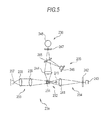
- Fig. 5 shows the outline configuration of an optical detecting section for detecting WBC/DIFF (white blood cells of five classifications) which is provided in the detecting section 23.
- the optical detecting section 23a is configured to send the measuring sample into a flow cell 231, generate a liquid current in the flow cell 231, and perform measuring by irradiating the blood cells included in the liquid current passing through the flow cell 231 with a semiconductor laser light.
- the optical detecting section includes a sheath flow system 232, a beam spot forming system 233, a forward-scattered light receiving system 234, a side-scattered light receiving system 235, and a side-fluorescence light receiving system 236.
- the sheath flow system 232 is configured such that the sample flows in the flow cell 231 in a state of being surrounded by a sheath fluid and in a state where the blood cells are aligned in a single line, so that the accuracy and reproducibility of the blood cell counting can be improved.
- the beam spot forming system 233 is configured such that light irradiated from a semiconductor laser 237 passes through a collimator lens 238 and a capacitor lens 239 so as to irradiate the flow cell 231.
- the beam spot forming system 233 is provided with a beam stopper 240.
- the forward-scattered light receiving system 234 is configured such that the forward-scattered light is condensed by a forward-condensing lens 241, and the light passing through a pin hole 242 is received by a photo diode (forward-scattered light receiving section) 243.
- the side-scattered light receiving system 235 is configured such that the side-scattered light is condensed by a side-condensing lens 244, and a part of the light is reflected on a dichroic mirror 245 so as to be received by a photo diode (side-scattered light receiving section) 246.
- Light scattering is a phenomenon occurring such that the particles of the blood cells act as an obstacle in terms of the traveling direction of light, and the light changes its traveling direction.
- information on the size or the material of the particles can be obtained.
- the information on the size of the particles (blood cells) can be obtained from the forward-scattered light.
- the information on the content of the particles can be obtained from the side-scattered light.
- the side-scattered light intensity depends on the complexity of the inside of the cell (shape, size, density, or granulated amount of nucleus). Therefore, using the characteristics of the side-scattered light intensity, the measurement of the white blood cell classification and the other measurements can be carried out.
- the side-fluorescence light receiving system 236 is configured such that the light which has passed through the dichroic mirror 245 further passes through a spectral filter 247 and is received by an avalanche photodiode (fluorescence light receiving system) 248.
- the sample container transport section 25 is provided with a hand section 25a which can grasp the sample container T.
- the hand section 25a is provided with a pair of grasping members which are disposed so as to face each other. The grasping members can be moved closer to or moved away from each other. The grasping members can grasp the sample container T by being moved closer to each other in a state where the sample container T is interposed therebetween.
- the sample container transport section 25 can move the hand section 25a in a vertical direction and in a backward or forward direction (Y direction), and can also oscillate the hand section 25a.
- the sample container T which is contained in the sample rack L and positioned at a first sample container take-out/returning position 43a is grasped by the hand section 25a.
- the hand section 25a moves upward, so that the sample container T is pulled out of the sample rack L, and the hand section 25a is oscillated, so that the sample in the sample container T can be stirred.
- the sample container transport section 25 is provided with a sample container setting section 25b which incudes a hole section through which the sample container T can be inserted.
- the sample container T grasped by the above-mentioned hand section 25a moves after the stirring is completed. Then, the grasped sample container T is inserted into the hole section of the sample container setting section 25b. Thereafter, the grasping members are moved away from each other, so that the sample container T is released from the hand section 25a, and the sample container T is set in the sample container setting section 25b.
- the sample container setting section 25b can horizontally move in the Y direction by a driving force of the stepping motor.
- a bar-code reading section 26 is provided in the first measurement unit 2.
- the sample container setting section 25b can move to a bar-code reading position 26a near the bar-code reading section 26 and a aspirating position 21a at which aspiration is carried out by the sample aspirating section 21.
- the sample container setting section 25b moves to the bar-code reading position 26a, the set sample container T is horizontally rotated by a rotation mechanism and the sample bar-code is read by the bar-code reading section 26.
- the bar-code label BL1 of the sample container T can face the bar-code reading section 26 by rotating the sample container T and the bar-code reading section 26 can read the sample bar-code.
- the sample container setting section 25b is moved to the aspirating position, the sample is aspirated from the set sample container T by the sample aspirating section 21.
- the configuration of the second measurement unit 3 is the same as that of the first measurement unit 2.
- the second measurement unit 3 includes a sample aspirating section 31, a sample preparing section 32 which prepares a measuring sample to be used in measuring of the blood components, such as blood cells, from the blood aspirated by the sample aspirating section 31, and a detecting section 33 which detects the blood cells from the measuring sample prepared by the sample preparing section 32.
- the second measurement unit 3 further includes a take-in port 34 (see Figs.
- sample container transport section 35 which loads the sample container T from the sample rack L into the second measurement unit 3 and transports the sample container T up to an aspirating position by the sample aspirating section 31.
- the configurations of the sample aspirating section 31, the sample preparing section 32, the detecting section 33, the take-in port 34, the sample container transport section 35, and the bar-code reading section 36 are the same as those of the sample aspirating section 21, the sample preparing section 22, the detecting section 23, the take-in port 24, and the sample container transport section 25, so that the descriptions thereof will be omitted.
- the second measurement unit 3 can perform the measurement of the sample regarding each of the measurement items, such as WBC which is the above-mentioned CBC+DIFF item, RBC, PLT, HGB, NEUT, LYMPH, EO, BASO, and MONO.
- WBC which is the above-mentioned CBC+DIFF item
- RBC the above-mentioned CBC+DIFF item
- PLT the above-mentioned CBC+DIFF item
- HGB the above-mentioned CBC+DIFF item
- NEUT HE
- LYMPH EO
- BASO BASO
- MONO MONO
- the first measurement unit 2 and the second measurement unit 3 can take in the sample container T containing another sample while a measuring sample prepared from one sample is measured by the detecting sections 23 and 33.
- the sample transport unit 4 is disposed in front of the first measurement unit 2 and the second measurement unit 3 of the sample processing apparatus 1.
- the sample transport unit 4 can transport the sample rack L in order to supply the sample to the first measurement unit 2 and the second measurement unit 3.
- Fig. 6 is a plan view illustrating the configuration of the sample transport unit 4.
- the sample transport unit 4 is provided with a before-analysis rack holding section 41, an after-analysis rack holding section 42, the rack transport section 43, a bar-code reading section 44, and a sample container sensor 45 (see Fig. 4 ) which detects the existence of the sample container T.
- the before-analysis rack holding section 41 can temporarily hold the plural sample racks L which hold the sample containers T which have yet to be subjected to the analysis.
- the after-analysis rack holding section 42 can temporarily hold the plural sample racks L which hold the sample container T in which the sample has been aspirated by the first measurement unit 2 and the second measurement unit 3.
- the rack transport section 43 horizontally moves the sample rack L in a straight line in the arrow direction X in order to supply the sample to the first measurement unit 2 or the second measurement unit 3. Then, the rack transport section transports the sample rack L received from the before-analysis rack holding section 41 to the after-analysis rack holding section 42.
- the before-analysis rack holding section 41 has a quadrangular shape in plan view, and its width is slightly larger than the width of the sample rack L.
- the before-analysis rack holding section 41 is formed to be lower by one stage than the surrounding surface, and on an upper face thereof, the before-analysis sample racks L are held.
- rack sending sections 41 b are provided in both faces of the before-analysis rack holding section 41 so as to protrude inward. The rack sending sections 41 b protrude, and thus the sample rack L comes into contact with the rack sending sections 41 b. In this state, the rack sending sections are moved backward (a direction so as to be closer to the rack transport section 43) and thus the sample rack L is moved backward.
- the rack sending sections 41 b are configured to be driven by a stepping motor which is provided below the before-analysis rack holding section 41.
- the rack transport section 43 can move the sample rack L sent by the before-analysis rack holding section 41 in the X direction as described above.
- the rack transport section 43 on the transport path of the sample rack L by the rack transport section 43, there are the first sample container take-out/returning position 43a at which the sample container containing the sample as an aspiration subject of the first measurement unit 2 is taken out from the sample rack L, and second sample container take-out/returning position 43b at which the sample container containing the sample as an aspiration subject of the second measurement unit 3 is taken out from the sample rack L.
- the hand section 25a or a hand section 35a of the corresponding measurement unit grasps the transported sample container T and takes out the sample container T from the sample rack L so as to supply the sample to the first measurement unit 2 or the second measurement unit 3.
- the hand section 25a or 35a grasping the sample container T enters into the housing of the first measurement unit 2 or the second measurement unit 3 as described above, and thereby the sample is taken into the first measurement unit 2 or the second measurement unit 3.
- the rack transport section 43 can transport the sample rack L also while the sample is being taken in the first measurement unit 2 or the second measurement unit 3. Therefore, since another sample cannot be taken into the measurement unit while one of the first measurement unit 2 and the second measurement unit 3 is being taken in with the sample, the sample rack L can be transported to the other measurement unit so as to take in the sample.
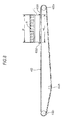
- the rack transport section 43 has two independently operable belts, that is, a first belt 431 and a second belt 432.
- Width b1 in a direction of the arrow Y of the first belt 431 and the second belt 432 is equal to or greater than half of a width B in the direction of the arrow Y of the sample rack L.
- the first belt 431 and the second belt 432 are disposed in parallel so as not to protrude from the width B of the sample rack L when the rack transport section 43 transports the sample rack L.
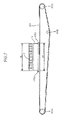
- Fig. 7 is a front view illustrating the configuration of the first belt 431, and Fig.
- FIG. 8 is a front view illustrating the configuration of the second belt 432.
- the first belt 431 and the second belt 432 are annularly formed.
- the first belt 431 is disposed so as to surround rollers 431 a to 431 c and the second belt 432 is disposed so as to surround rollers 432a to 432c.
- two protrusions 431 d are provided so as to have an inner width w1 slightly larger (for example, 1 mm) than a width W in the X direction of the sample rack L, and similarly as shown in Fig.
- the first belt 431 is configured such that the sample rack L held inside of the two protrusions 431 d is moved in the direction of the arrow X by being moved along the outer peripheries of the rollers 431 a to 431c by a stepping motor.
- the second belt 432 is configured such that the sample rack L held inside of the two protrusions 432d is moved in the direction of the arrow X by being moved along the outer peripheries of the rollers 432a to 432c by a stepping motor.
- the first belt 431 and the second belt 432 are configured so as to move the sample rack L independently of each other. Therefore, the rack transport section 43 can transport the sample rack L such that the sample is transported up to the first sample container take-out/returning position 43a, the second sample container take-out/returning position 43b, and a reading position 43d for reading the bar-code printed on the bar-code label BL1 of the sample container T by the bar-code reading section 44.
- the bar-code reading section 44 is configured to read the bar-code printed on the bar-code label BL1 of the sample container T shown in Fig. 5 , and to read the bar-code printed on the bar-code label BL2 which is attached to the sample rack L.
- the bar-code reading section 44 is configured to read the bar-code of the sample container T while the sample container T of the subject accommodated in the sample rack L is being rotated in the horizontal direction by a rotation apparatus. Therefore, even when the bar-code of the sample container T is attached to an opposite side with respect to the bar-code reading section 44, by rotating the sample container T, the bar-code can face the bar-code reading section 44.
- the bar-code printed on the bar-code label BL2 of the sample rack L is uniquely assigned to each rack and used to manage the analysis result of the sample.
- the sample container sensor 45 is a contact sensor and has a contact piece, a light-emitting element for emitting light, and a light-receiving element.
- the sample container sensor 45 is configured such that the contact piece is bent when brought into contact with a substance to be detected which is a detection object and the light emitted from the light-emitting element is thus reflected by the contact piece and enters the light-receiving element. Accordingly, while the sample container T which is a detection object accommodated in the sample rack L passes under the sample container sensor 45, the contact piece is bent by the sample container T and the sample container T can be detected.
- the sample container sensor 45 is provided at the bar-code reading position 43d. Therefore, the existence of the sample container T at the bar-code reading position 43d can be detected by the sample container sensor 45.
- a rack delivery section 46 is provided in the rear side of the after-analysis rack holding section 42.
- the rack delivery section 46 is configured to horizontally move in a straight line in the direction of the arrow Y by a driving force of the stepping motor. Therefore, when the sample rack L is transported to a position 461 (hereinafter, referred to as "after-analysis rack delivery position") between the after-analysis rack holding section 42 and the rack delivery section 46, the sample rack L can be moved into the after-analysis rack holding section 42 by moving the rack delivery section 46 toward the after-analysis rack holding section 42.
- the after-analysis rack holding section 42 has a quadrangular shape in plan view, and its width is slightly larger than the width of the sample rack L.
- the after-analysis rack holding section 42 is formed to be lower by one stage than the surrounding surface, and on an upper face thereof, the analyzed sample racks L are held.
- the after-analysis rack holding section 42 is connected to the above-mentioned rack transport section 43 and, as described above, sends the sample rack L from the rack transport section 43 by the rack delivery section 46.
- the sample transport unit 4 moves the sample rack L held on the before-analysis rack holding section 41 to the rack transport section 43, and the sample rack is further transported by the rack transport section 43 so that the sample can be supplied to the first measurement unit 2 or the second measurement unit 3.
- the sample rack L accommodating the samples which are completely aspirated is moved to the after-analysis rack delivery position 461 by the rack transport section 43, and delivered to the after-analysis rack holding section 42 by the rack delivery section 46.
- the sample racks L accommodating the samples which are completely analyzed are sequentially delivered to the after-analysis rack holding section 42 by the rack delivery section 46.
- the plural sample racks L are stored in the after-analysis rack holding section 42.
- the information processing unit 5 is composed of a computer.
- Fig. 9 is a block diagram illustrating the configuration of the information processing unit 5.
- the information processing unit 5 is realized by a computer 5a.
- the computer 5a includes a main body 51, an image display section 52 and an input section 53.
- the main body 51 includes a CPU 51 a, a ROM 51 b, a RAM 51 c, a hard disk 51 d, a reading device 51 e, an I/O interface 51f, a communication interface 51 g and an image output interface 51 h.
- the CPU 51a, ROM 51b, RAM 51c, hard disk 51d, reading device 51e, I/O interface 51f, communication interface 51 g and image output interface 51 h are connected to each other by a bus 51j.
- the CPU 51 a can execute a computer program loaded to the RAM 51 c.
- the CPU 51 a executes a computer program 54a for analyzing a sample and controlling the first measurement unit 2, the second measurement unit 3, and the sample transport unit 4, which will be described later, so that the computer 5a functions as the information processing unit 5.
- the ROM 51 b is composed of a mask ROM, a PROM, an EPROM, an EEPROM or the like and the computer program executed by the CPU 51a and data used for the computer program are recorded in the ROM.
- the RAM 51c is composed of a SRAM, a DRAM or the like.
- the RAM 51c is used to read the computer program 54a recorded in the hard disk 51 d.
- the RAM is used as an operating area of the CPU 51 a when the CPU 51 a executes a computer program.
- measurement unit state data areas S1 and S2 showing the states of the first measurement unit 2 and the second measurement unit 3 are provided.
- the measurement unit state data areas S1 and S2 any one of "Sample Take-in Possible", “Sample Take-in/Returning Impossible", and “Sample Returning Possible” is stored as data.
- the state of the measurement unit becomes "Sample Take-in Possible”.
- the state of the measurement unit becomes "Sample Take-in/Returning Impossible”.
- the state of the measurement unit becomes "Sample Returning Possible”.
- the measurement unit measures the measuring sample by the detecting sections 23 and 33 (that is, detecting the blood cell) and the returning of the sample container T is completed, the state of the measurement unit becomes "Sample Take-in Possible” in which a new sample can be taken in.
- the RAM 51c areas of state queues Q1 and Q2 in which the state data of the first measurement unit 2 and the second measurement unit 3 is stored are provided.
- the state queues Q1 and Q2 receive the state data of the first measurement unit 2 and the second measurement unit 3 in real time, and store the state data in a FIFO list structure.
- various computer programs for execution by the CPU 51a such as an operating system and an application program, and data which is used to execute the computer programs, are installed.
- the computer program 54a to be described later is also installed in the hard disk 51 d.
- the reading device 51 e is composed of a flexible disk drive, a CD-ROM drive, a DVD-ROM drive or the like and can read the computer program or data recorded in a portable recording medium 54.
- the computer program 54a for prompting the computer to function as the information processing unit 5 is stored.
- the computer 5a can read the computer program 54a from the portable recording medium 54 and install the computer program 54a in the hard disk 51d.
- the computer program 54a is provided by the portable recording medium 54 and can be also provided from an external device, which is connected to the computer 5a by an electric communication line (which may be wired or wireless) to communicate therewith, through the electric communication line.
- the computer program 54a is stored in a hard disk of a server computer on the internet and the computer 5a accesses the server computer to download the computer program and install the computer program in the hard disk 51d.
- the hard disk 51d for example, a multitasking operating system such as Windows (registered trade name), which is made and distributed by Microsoft corporation in America, is installed.
- Windows registered trade name
- the computer program 54a according to this embodiment operates on the above operating system.
- the I/O interface 51f is composed of, for example, a serial interface such as USB, IEEE1394 or RS-232C, a parallel interface such as SCSI, IDE or IEEE1284, and an analog interface including a D/A converter and an A/D converter.
- the input section 53 composed of a keyboard and a mouse is connected to the I/O interface 51f and the user uses the input section 53 so as to input data to the computer 5a.
- the I/O interface 51f is connected to the first measurement unit 2, the second measurement unit 3, and the sample transport unit 4. Therefore, the information processing unit 5 can control the first measurement unit 2, the second measurement unit 3, and the sample transport unit 4.
- the communication interface 51 g is an Ethernet (registered trade name) interface.
- the communication interface 51g is connected to a host computer 6 via a LAN.
- the computer 5a can send and receive data to and from the host computer 6 connected to the LAN by using a predetermined communication protocol.
- the image output interface 51h is connected to the image display section 52 composed of a LCD or a CRT so as to output a picture signal corresponding to the image data provided from the CPU 51 a to the image display section 52.
- the image display section 52 displays an image (screen) in accordance with an input picture signal.
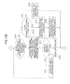
- Figs. 10A and 10B are flowcharts illustrating the flow of the sample transport controlling process carried out by the information processing unit 5 of the sample processing apparatus 1.
- An operator places the sample rack L accommodating the plural sample containers T, which contain samples, on the before-analysis rack holding section 41. In this state, the operator operates the input section 53 so as to instruct the information processing unit 5 to perform the sample measuring.
- the CPU 51a of the information processing unit 5 receives the instruction of performing the sample measuring, and then performs the following sample transport controlling process.
- the CPU 51 a secures an area for sample processing table which is used to measure the sample by the RAM 511c (Step S102).
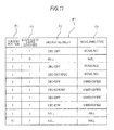
- a sample processing table PT is a table for securing each piece of the information on, such as, the holding position of each sample in the sample rack L, the existence of the sample container, the measuring order, and the measuring state of the sample, for each sample rack L.
- the sample processing table PT is composed of 10 rows, and each row corresponds to the sample which is accommodated to the sample rack L.
- a field (column) F1 of the holding position of the sample rack L, a field F2 of the existence of the sample, a field F3 of the measuring order, and a field F4 of the measuring state are provided in the sample processing table PT.
- the field F1 information of "1" to “10" showing the holding positions of the sample in the sample rack L is stored.
- the field F2 when there is the sample container T at the corresponding holding position, "1" is stored, and when there is no sample container T at the corresponding holding position, "0" is stored.
- the field F3 information of the measurement item showing the measuring order is stored.
- the CBC+DIFF item includes each item of WBC, RBC, PLT, HGB, NEUT, LYMPH, EO, BASO, and MONO, the respective pieces of the information of the measurement items may be individually stored in the field F3 and, as shown in Fig. 11 , the information representing the "CBC+DIFF" may be stored in the field F3.
- any one of four type information that is, "Unmeasured”, "Take-in Sample (first measurement unit)", “Take-in Sample (second measurement unit)", and "Measured” is stored as information indicating measuring state.
- Step S102 all the respective cells are in a state of being filled with a blank (NULL is stored) excepting the field F1 of the sample processing table PT.
- NULL NULL is stored
- all the samples of the sample rack L corresponding to one sample processing table PT is processed, and the following processes are carried out on the one sample processing table PT as a subject until the samples are transported to the after-analysis rack holding section 42, and then the following processes are carried out on the other sample processing table PT.
- the CPU 51a refers to the state queues Q1 and Q2 so as to store the data showing the state of the first measurement unit 2 and the second measurement unit 3 at this point of time in the measurement unit state data areas S1 and S2 (Step S103).
- the plural state data may be stored.
- the CPU 51 a sequentially reads out the state data from the state queues Q1 and Q2, and stores the finally-read data in the measurement unit state data areas S1 and S2.
- the data which is finally read from the state queues Q1 and Q2 shows the final state of the first measurement unit 2 and the second measurement unit 3, that is, the state of the first measurement unit 2 and the second measurement unit 3 at this point of time.
- initial values of the state queues Q1 and Q2 are "Sample Take-in Possible".
- the CPU 51a determines whether or not the sample rack L can be discharged (Step S104).
- the CPU 51a refers to the sample processing table PT so as to store any one of "0" and "1" to the field F2 with respect to all the holding positions (that is, there is no cell filled with "NULL").
- "Measured” is stored in the field F4 in all the records in which "1" is stored in the field F2
- there is no sample container T which is necessary to be subjected to the process in the sample container T accommodated to the sample rack L so that the sample rack L can be discharged.
- Step S104 when the sample rack L cannot be discharged (NO in Step S104), the CPU 51 a determines whether or not there is a necessity-for-process sample with reference to the sample processing table PT (Step S105).
- the "Necessity-For-Process Sample” indicates a sample which is confirmed of the measuring order and is not measured. That is, in the sample processing table PT, a sample in which the information of the measuring order is stored in the field F3 and the information of the "Unmeasured" is stored in the field F4 corresponds to the "Necessity-For-Process Sample".
- Step S105 when there is a necessity-for-process sample (YES in Step S105), the CPU 51a performs a sample transport destination determining process (Step S106).
- Fig. 12 is a flowchart illustrating the procedure of the sample transport destination determining process.
- the CPU 51a first refers to the sample processing table PT so as to select a necessity-for-process sample of which the holding position number is minimized (Step S201).
- the CPU 51a refers to the measurement unit state data area S1 of the RAM 51 c so as to determine whether or not the state of the first measurement unit 2 is "Sample Take-in Possible" (Step S202).
- Step S202 when the state of the first measurement unit 2 is "Sample Take-in Possible" (YES in Step S202), the CPU 51a determines the first measurement unit 2 to the transport destination (Step S203), and returns the process to an invoked address of the sample transport destination determining process.
- Step S202 when the state of the first measurement unit 2 is "Sample Take-in/Returning Impossible" or “Sample Returning Possible” (NO in Step S202), the CPU 51a refers to the measurement unit state data area S2 of the RAM 51 c so as to determine whether or not the state of the second measurement unit 3 is "Sample Take-in Possible” (Step S204).
- Step S204 when the state of the second measurement unit 3 is "Sample Take-in Possible" (YES in Step S204), the CPU 51 a determines the second measurement unit 3 to the transport destination (Step S205), and returns the process to an invoked address of the sample transport destination determining process.
- Step S204 when the state of the second measurement unit 3 is "Sample Take-in/Returning Impossible" or “Sample Returning Possible” (NO in Step S204), the CPU 51a determines the transport destination as "NO" (Step S206), and returns the process to an invoked address of the sample transport destination determining process.
- the CPU 51 a determines whether the determined transport destination is the first measurement unit 2 or the second measurement unit 3 (Step S107).
- the CPU transports the sample selected in the sample transport destination determining process to the transport destination (Step S108). Further, in this process, when the transport destination is the first measurement unit 2, the CPU 51 a controls the sample transport unit 4 to position the selected sample at the first sample container - take-out/returning position 43a.
- the CPU controls the sample transport unit 4 to position the selected sample at the second sample container takeout/returning position 43b.
- the CPU 51 a inputs "Sample Take-in/Returning Impossible" to the state queue corresponding to the measurement unit of the transport destination (Step S109). In addition, the CPU 51a changes the measuring state in the sample processing table PT of the sample to "Sample Take-in (first measurement unit)" in order to except the sample from the necessity-for-process sample, so that the sample process table PT is updated (Step S110).
- the CPU 51 a controls the sample container transport section of the measurement unit of the transport destination and pulls out the sample container T positioned at the sample container take-out/returning position from the sample rack L (Step S111). Thereafter, the CPU 51a performs a sample take-in process and a sample measuring process to be described later. Therefore, the selected sample container T is taken in the first measurement unit 2 or the second measurement unit 3, and the sample is aspirated from the sample container T. Since the sample take-in process takes tens of seconds, after the process of Step S111 described above is completed, the CPU 51 a returns the process to Step S103, and performs the subsequent processes of Step S103 in parallel to the sample take-in process.
- Step S105 when there is no necessity-for-process sample (NO in Step S105), or when the transport destination determined by the sample transport destination determining process in Step S107 is "NO" (NO in Step S107), the CPU 51a refers to the measurement unit state data areas S1 and S2 so as to determine whether or not there is a measurement unit of which the apparatus state is "Sample Returning Possible” (Step S112).
- the CPU 51a transports the sample rack L to the one of which the state information is "Sample Returning Possible” among the first measurement unit 2 and the second measurement unit 3 (Step S113).
- the CPU 51 a refers to the sample processing table PT, and transport the sample rack L such that the holding position corresponding to the record of which the field F4 is stored with "Sample take-in (first measurement unit)" is changed to the first sample container take-out/returning position 43a.
- the CPU 51 a refers to the sample processing table PT and transports the sample rack L such that the holding position corresponding to the record of which the field F4 is stored with "Sample Take-in (second measurement unit)" is changed to the second sample container take-out/returning position 43b.
- the CPU 51 a transports the sample rack L by setting the first measurement unit 2 to the transport destination.
- Step S114 the CPU 51a performs the sample returning process.
- one of the first measurement unit 2 and the second measurement unit 3, which is in the state of "Sample Returning Possible” is controlled, so that the sample container T is discharged from the measurement unit and returns to the sample rack L.
- the measuring state in the sample processing table PT of the returned sample is changed to "Measured", so that the sample processing table PT is updated. The details of the sample returning process will be described later.
- the CPU 51 a returns the process to Step S103.
- Step S112 when "Sample Returning Possible” is not stored in both the measurement unit state data areas S1 and S2 (NO in Step S112), the CPU 51a refers to the sample processing table PT so as to determine whether or not there is a holding position for which the measuring order is not confirmed, that is, a holding position for which the information "0" indicating no sample is not stored in the field F2 in the sample processing table PT and the information of the measuring order is not stored in the field F3 (see Fig. 10B , Step S115).
- Step S115 when there is a holding position for which the measuring order is not confirmed (YES in Step S115), the CPU 51 a controls the sample transport unit 4 so as to transport the sample rack L, and positions one at a holding position of the sample rack L, for which the measuring order is not confirmed in the holding position of the corresponding sample rack L, to the reading position 43d in front of the bar-code reading section 44 (Step S116).
- being positioned at the reading position 43d is to be positioned at a holding position (a holding position on the downstream end side in the transport direction of the sample rack L) with a smallest number in the holding positions for which "0" is not stored in the field F2 in the sample processing table PT and the information of the measuring order is not stored in the field F3.
- the holding position "1" is selected, and the sample rack L is transported such that the holding position "1" becomes the reading position 43d.
- the holding position "2" is selected, and the sample rack L is transported such that the holding position "2" becomes the reading position 43d. Therefore, the sample rack is positioned at the reading position 43d in the order increasing the number thereof.
- Step S117 When the sample rack L is transported such that the selected holding position becomes the reading position 43d, the CPU 51 a determines whether or not the sample container T is detected by the sample container sensor 45 (Step S117). Here, when the sample container T is detected (YES in Step S117), the sample ID is read from the sample bar-code of the sample container T by the bar-code reading section 44 (Step S118).
- the CPU 51 a performs the measuring order obtaining process as to be described later.
- the CPU 51a obtains the measuring order of the sample.
- the measuring order obtaining process is performed in parallel with the sample transport controlling process by a multitasking process. Therefore, while the measuring order obtaining process is performed, the transportation of the sample rack L becomes possible.
- Step S11T when the sample container T is not detected (NO in Step S117), the CPU 51 a stores "0" in the cell corresponding to the holding position of the field F2 in the sample processing table PT (Step S119), and returns the process to Step S115.
- Step S115 when there is no holding position for which the measuring order is not confirmed (NO in Step S115), the CPU 51a determines whether or not a new sample rack L can be sent to the rack transport section 43 (Step S120).
- Step S120 the CPU 51a can transport a new sample rack L when the sample rack L held on the before-analysis rack holding section 41 is detected by a sensor, the fields F2 of all the holding positions before a predetermined holding position (for example, the holding position "7") are stored with any one of "0" and "1" in the sample processing table PT relating to the sample rack L which is being currently transported by the rack transport section 43 (that is, there is no cell set with "NULL"), and "Measured" is stored in the fields F4 in all the records of which the fields F2 are stored with "1".
- Step S120 when a new sample rack L can be transported (YES in Step S120), the CPU 51 a secures an area for a new sample processing table in the RAM 51c (Step S121). Further, the CPU 51a controls the rack sending sections 41 b, so that a new sample rack L is moved by the before-analysis rack holding section 41 so as to be sent to the rack transport section 43 (Step S122). At this time, the CPU performs a transport control on the transport section 43 in order not to occur interference between the current transported sample rack L and a newly sent sample rack L with each other, and thus the new sample rack L is sent to the rack transport section 43. After completing the process of Step S122, the CPU 51 a returns the process to Step S103.
- Step S120 when a new sample rack L cannot be transported (NO in Step S120), the CPU 51a stands by for a predetermined period of time (for example, 1 sec) (Step S123), and then returns the process to Step S103.
- the CPU refers to the state queues Q1 and Q2 so as to store data showing the state of the first measurement unit 2 and the second measurement unit 3 at this point of time in the measurement unit state data areas S1 and S2 (Step S103).
- Step S104 when the measuring states of all the samples are "Measured" in the sample processing table PT (YES in Step S104), the CPU 51 a controls the sample transport unit 4 such that the sample rack L (the left sample rack L when two sample racks L are on the rack transport section 43) is transported to the after-analysis holding section 42 by the rack transport section 43 (see Fig. 10A , Step S124).
- the CPU releases an area of the sample processing table PT corresponding to the sample rack L, in the RAM 51 c (Step S125), and returns the process to Step S103.
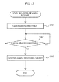
- FIG. 13 is a flowchart illustrating the flow of the measuring order obtaining process carried out by the information processing unit 5 of the sample processing apparatus 1.
- the CPU 51a first makes an inquiry to the host computer 6 for the measuring order corresponding to the sample ID (Step S301).
- the inquiry is carried out by transmitting measuring order request data including the sample ID to the host computer 6 which is connected via a network.
- the CPU 51a stands by to receive the measuring order (NO in Step S302).
- the CPU When receiving the measuring order (YES in Step S302), the CPU stores "1" in the cell of field F2 which indicates the existence of the sample container corresponding to the holding position, stores the measuring order in the cell of field F3 of the measuring order, and stores the information of the "Unmeasured” in the field F4 of the measuring state in the sample processing table PT, so that the sample processing table PT is updated (Step S303) and the measuring order obtaining process is completed.
- the above-mentioned measuring order obtaining process is performed, in parallel with the sample transport controlling process by a multitasking process. Therefore, while the measuring order obtaining process is performed, the transportation of the sample rack L becomes possible.
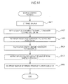
- FIG. 14 is a flowchart illustrating the flow of the sample take-in process carried out by the information processing unit 5 of the sample processing apparatus 1.
- the sample take-in process carried out by the first measurement unit 2 is described, and the sample take-in process carried out by the second measurement unit 3 is also similar thereto.
- the sample take-in process by the first measurement unit 2 is performed by the CPU 51a.
- the CPU 51 a first controls the hand section 25a to oscillate the sample container T, and thus the sample therein is stirred for a predetermined period of time (Step S401). The stirring of the sample takes a time about tens of seconds.
- the CPU 51 a controls the hand section 25a so as to set the sample container T to the sample container setting section 25b (Step S402), and further controls the sample container transport section 25 so as to transport the sample container T to the aspirating position (Step S403). Further, the CPU 51a refers to the measuring order of the sample to calculate a sample amount required for the measuring from the measurement items (Step S404). Next, the CPU 51a controls the sample aspirating section 21 so as to aspirate an amount necessary for the sample from the sample container T (Step S405).
- Step S405 since the first measurement unit 2 is in a state capable of returning the sample, the CPU 51a inputs the information of the "Sample Returning Possible" in the state queue Q1 (Step S406), and completes the process.
- the above-mentioned sample take-in process is performed in parallel with the sample transport controlling process by a multitasking process. Therefore, while the sample take-in process is performed, the transportation of the sample rack L becomes possible.
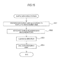
- FIG. 15 is a flowchart illustrating the flow of the sample measuring process carried by the information processing unit 5 of the sample processing apparatus 1.
- the sample measuring process carried out by the first measurement unit 2 is described, and the sample measuring process carried out by the second measurement unit 3 is also similar thereto.
- the CPU 51a performs the sample measuring process.
- the CPU 51a first controls the sample preparing section 22 so as to prepare the measuring samples corresponding to the measurement items (Step S501).
- the CPU 51a supplies the measuring sample to the detecting section 23 so as to carry out the measurement of the sample regarding each measurement item included in the measuring order by the detecting section 23 (Step S502). Therefore, the CPU 51 a obtains measurement data output from the detecting section 23.
- the CPU 51a performs a cleaning operation for cleaning a flow path used for the measurement and a reaction chamber (Step S503).
- the CPU 51 a performs an analysis process of the measurement data (Step S504) so as to obtain the analysis result of the numerical values including, such as, RBC, PLT, HGB,WBC, NEUT, LYMPH, EO, BASO, and MONO. After the process of Step S504 is completed, the CPU 51 a completes the process.
- the above-mentioned sample measuring process is performed in parallel with the sample transport controlling process by a multitasking process. Therefore, while the sample measuring process is performed, the transportation of the sample rack L becomes possible.
- FIG. 16 is a flowchart illustrating the flow of the sample returning process carried out by the information processing unit 5 of the sample processing apparatus 1.
- the sample returning process carried out by the first measurement unit 2 is described, and the sample returning process carried out by the second measurement unit 3 is also similar thereto.
- the CPU 51 a first controls the sample container transport section 25 and moves the sample container setting section 25b from the aspirating position to be transported up to a position where the sample container T can be grasped by the hand section 25a (Step S601).
- the CPU 51a controls the hand section 25a so as to grasp the sample container T by the hand section 25a, and then pulls out the sample container T from the sample container setting section 25b (Step S602).
- the CPU 51 a controls the hand section 25a so as to insert the grasped sample container T to the holding position of the sample rack L of the first sample container take-out/returning position 43a (Step S603).
- the CPU 51 a inputs "Sample Take-in Possible” in the state queue Q1 of the RAM 51 c (Step S604). Furthermore, the CPU 51 a changes the measuring state in the sample processing table PT of the sample, returned to the sample rack L to "Measured" (Step S605). After the process of Step S605 is completed, the CPU 51 a returns the process to an invoked address of the sample returning process.
- sample processing apparatus 1 Next, the operation of the above-mentioned sample processing apparatus 1 will be described using a specific example. In the following, the operation of the sample processing apparatus 1 will be described in a case where the sample rack L holding the samples of which the measurement items include the CBC+DIFF item at the holding positions 1 to 10 is put into the sample processing apparatus 1.
- Fig. 17 is a timing chart illustrating the operations of the first measurement unit 2 and the second measurement unit 3 of the sample processing apparatus 1 when the sample rack L is put into the sample processing apparatus 1.
- the sample rack L is put into the before-analysis rack holding section 41, and when the information processing unit 5 is instructed to perform the sample measuring by an operator, the sample rack L held on the before-analysis rack holding section 41 is detected (Step S101 in Fig. 10A ), and an area of the sample processing table PT in the information processing unit 5 is secured (Step S102).
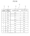
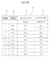
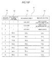
- Figs. 18A to 18G are diagrams schematically illustrating the state of the sample processing table PT.
- the state of the sample processing table PT in this point of time is shown in Fig. 18A .
- the sample processing table PT is in a state where all cells are filled with NULL data excepting the field F1.
- the CPU 51a refers to the state queues Q1 and Q2, the finally input data in the state queues Q1 and Q2 is stored in the measurement unit state data areas S1 and S2 (Step S103).
- the initial value of "Sample Take-in Possible” is input in both state queues Q1 and Q2
- “Sample Take-in Possible” is stored in the respective measurement unit state data areas S1 and S2.
- Step S104 the CPU 51 a determines whether or not the sample rack L can be discharged. However, since all the fields F2 showing the existence of the sample container of the sample processing table PT are stored with "NULL" (NO in Step S104), the process of the CPU 51a moves to Step S105. In addition, it is determined whether or not there is a necessity-for-process sample in Step S105. However, since there is no necessity-for-process sample in the sample processing table PT (NO in Step S105), the process of the CPU 51a moves to Step S112.
- Step S112 the CPU 51 a determines whether or not there is a measurement unit of which the apparatus state is "Sample Returning Possible” (Step S112).
- Step S112 the process of the CPU 51 a moves to Step S115.
- the CPU 51a determines whether or not there is a holding position for which the measuring order is not confirmed (Step S115).
- the sample processing table PT there is no record in which the information on the measuring order is stored in the field F3 of the measuring order. That is, there is only samples for which the measuring order is confirmed (YES in Step S115). Therefore, the CPU 51a moves the process to Step S116.
- Step S116 one of the samples accommodated in the sample rack L, its the holding position for which the measuring order is not confirmed, is transported up to the reading position 43d in front of the bar-code reading section 44 (Step S116).
- the sample rack L is transported until the holding position 1 becomes the reading position 43d. Since the sample container T is held at the holding position 1 of the sample rack L, the sample container T is detected by the sample container sensor 45 (YES in Step S117). Therefore, the sample ID is read from the bar-code of the sample positioned at the holding position 1 by the bar-code reading section 44 (Step S118), and the measuring order obtaining process is performed.
- the measuring order of the sample at the holding position 1, that is, the measuring order including the CBC+DIFF item is obtained from the host computer 6 by the CPU 51a (Steps S301 and S302).
- the sample processing table PT is updated (Step S303).
- the state of the sample processing table PT at this point of time is shown in Fig. 18B .
- "1" is stored in the field F2 showing the existence of the sample container T in the row of the holding position 1 of the sample processing table PT
- the information representing the "CBC+DIFF” is stored in the field F3 of the measuring order
- the information representing the "Unmeasured” is stored in the field F4 of the measuring state.
- the sample transport controlling process is performed continuously. That is, the CPU 51a performs the process of Step S103 again.
- the CPU 51 a refers to the state queues Q1 and Q2, and the finally input data in the state queues Q1 and Q2 is stored in the measurement unit state data areas S1 and S2 (Step S103).
- the data of the measurement unit state data areas S1 and S2 is not changed. That is, "Sample Take-in Possible" is stored in each of the measurement unit state data areas S1 and S2.
- Step S104 It is determined whether or not the sample rack L can be discharged, but since the sample rack L cannot be discharged (NO in Step S104), it is determined whether or not there is a necessity-for-process sample in Step S105.
- the sample at the holding position 1 is the necessity-for-process sample because there is information on the measuring order in the sample processing table PT and the measuring state is "Unmeasured". Therefore, the sample transport destination determining process S106 is performed by the CPU 51 a.
- the CPU 51a selects the necessity-for-process sample of which the number of the holding position is smallest in the sample processing table PT (Step S201). Therefore, the sample at the holding position 1 is selected, and it is determined whether or not the first measurement unit 2 is in the state where the sample can be taken in from the measurement unit state data area S1 of the RAM 51 c (Step S202).
- the information of the "Sample Take-in Possible” is stored in both of the measurement unit state data areas S1 and S2. Therefore, it is determined that the first measurement unit 2 can take in the sample (YES in Step S202), the first measurement unit 2 is determined as the transport destination (Step S203), and the process is returned to an invoked address of the sample transport destination determining process S106.
- the CPU 51 a determines whether the determined transport destination is the first measurement unit 2 or the second measurement unit 3 (Step S107). Since the transport destination is determined as the first measurement unit 2 (YES in Step S107), the sample at the holding position 1 is transported to the first sample container take-out/returning position 43a (Step S108).
- Step S109 the CPU 51a inputs "Sample Take-in/Returning Impossible" in the state queue Q1 of the RAM 51c (Step S109), and the measuring state of the holding position 1 of the sample processing table PT is changed so as to be "Sample Take-in (first measurement unit)" (Step S110).
- Step S110 the sample container T at the holding position 1, which is positioned at the first sample container take-out/returning position 43a, is pulled out of the sample rack L (Step S111).
- the state of the sample processing table PT at this point of time is shown in Fig. 18C .
- the sample take-in process is performed by the first measurement unit 2, and the sample container T is taken in the first measurement unit 2 (Steps S401 to S405).
- Step S103 the information of the “Sample Take-in/Returning Impossible” is stored in the measurement unit state data area S1 (Step S103).
- Step S104 since "NULL" is stored in the field F2 of the holding positions 2 to 10, the sample rack L cannot be discharged (NO in Step S104), there is not necessity-for-process sample (NO in Step S105), and there is no measurement unit of which the apparatus state is "Sample Returning Possible” (NO in Step S112).
- Step S115 since there is a holding position for which the measuring order is not confirmed (YES in Step S115), the holding position 2 of which the number of the holding position for which the measuring order is not confirmed is smallest becomes the reading position 43d (Step S116). Since the sample container T is held at the holding position 2, the sample container T is detected by the sample container sensor 45 (YES in Step S117). Therefore, the sample ID is read from the bar-code of the sample at the holding position 2 by the bar-code reading section 44 (Step S118), and the measuring order obtaining process is performed.
- the measuring order of the sample at the holding position 2 that is, the measuring order including the CBC+DIFF item is obtained from the host computer 6 by the CPU 51a (Steps S301 and S302).
- the sample processing table PT is updated (Step S303).
- the state of the sample processing table PT at this point of time is shown in Fig. 18D .
- "1" is stored in the field F2 showing the existence of the sample container T in the row of the holding position 2 of the sample processing table PT
- the information representing the "CBC+DIFF" is stored in the field F3 of the measuring order
- the information representing the "Unmeasured” is stored in the field F4 of the measuring state.
- the sample transport controlling process is continuously performed. That is, the CPU 51a performs the process of Step S103 again.
- the data in the measurement unit state data areas S1 and S2 are not changed in the process of Step S103. That is, “Sample Take-in/Returning Impossible” is stored in the measurement unit state data area S1, and “Sample Take-in Possible” is stored in the measurement unit state data area S2.
- Step S104 since "NULL" is stored in the field F2 of the holding positions 3 to 10, the sample rack L cannot be discharged (NO in Step S104), and it is determined whether or not there is a necessity-for-process sample in Step S105.
- the sample at the holding position 2 is the necessity-for-process sample. Therefore, the sample transport destination determining process S106 is performed by the CPU 51a.
- the CPU 51a selects the necessity-for-process sample of which the number of the holding position is smallest in the sample processing table PT (Step S201). Therefore, the sample at the holding position 2 is selected, and it is determined whether or not the first measurement unit 2 is in the state where the sample can be taken in from the measurement unit state data area S1 of the RAM 51 c (Step S202).
- the information of the "Sample Loading/Returning Impossible" is stored in the measurement unit state data area S1.
- Step S204 it is determined whether or not the second measurement unit 3 is in a state where the sample can be taken in from the measurement unit state data area S2 of the RAM 51 c.
- the information of the "Sample Loading Possible" is stored in the measurement unit state data area S2. Therefore, it is determined that the second measurement unit 3 can take in the sample (YES in Step S204), the second measurement unit 3 is determined as the transport destination (Step S205), and the process is returned to an invoked address of the sample transport destination determining process S106.
- the CPU 51 a determines whether the determined transport destination is the first measurement unit 2 or the second measurement unit 3 (Step S107). Since the transport destination is determined as the second measurement unit 3 (YES in Step S107), the sample at the holding position 2 is transported to the second sample container take-out/returning position 43b (Step S108).
- Step S109 the CPU 51 a inputs "Sample Take-in/Returning Impossible" in the state queue Q2 of the RAM 51 c (Step S109), and the measuring state of the holding position 2 of the sample processing table PT is changed so as to be "Sample Take-in (second measurement unit)" (Step S110). Then, the sample container T at the holding position 2, which is positioned at the second sample container take-out/returning position 43b, is pulled out of the sample rack L (Step S111). The state of the sample processing table PT at this point of time is shown in Fig. 18E .
- the sample take-in process is performed by the second measurement unit 3, and the sample container T is taken in the second measurement unit 3 (Steps S401 to S405). Further, as shown in Fig. 17 , the above-mentioned sample obtaining process of the sample container T at the holding position 1 is also performed in parallel therewith.
- the CPU 51a keeps on the sample transport controlling process during the above-mentioned sample take-in process is performed on the sample at the holding positions 1 and 2. In addition, when the sample take-in is completed, the sample measuring process is performed. The sample measuring process is also performed in parallel with the sample transport controlling process.
- the CPU 51 a performs the subsequent processes of Step S103 again during the sample take-in process is performed by the first measurement unit 2 and the second measurement unit 3.
- the finally input data in the state queue Q2 is "Sample Take-in/Returning Impossible”
- the information of the "Sample Take-in/Returning Impossible” is stored in the measurement unit state data area S2.
- the data stored in the measurement unit state data area S1 remains in "Sample Take-in/Returning Impossible", and is not changed (Step S103).
- Step S104 since the information representing the existence of the sample container T at the holding positions 3 to 10 in the sample processing table PT is "NULL", the sample rack L cannot be discharged (NO in Step S104). Since there is no necessity-for-process sample (NO in Step S105) and the measuring order of the sample at the holding positions 3 to 10 is not confirmed (YES in Step S115), the holding position 3 of which the number of the holding position for which the measuring order is not confirmed is smallest becomes the reading position 43d (Step S116). Since the sample container T is held on the holding position 3, the sample container T is detected by the sample container sensor 45 (YES in Step S117). Therefore, the sample ID is read from the bar-code of the sample at the holding position 3 by the bar-code reading section 44 (Step S118), and the measuring order obtaining process is performed.
- the measuring order of the sample at the holding position 3 that is, the measuring order including the CBC+DIFF item is obtained from the host computer 6 by the CPU 51a (Steps S301 and S302).
- the sample processing table PT is updated (Step S303).
- the state of the sample processing table PT at this point of time is shown in Fig. 18F .
- "1" is stored in the field F2 showing the existence of the sample container T in the row of the holding position 3 of the sample processing table PT
- the information representing the "CBC+DIFF" is stored in the field F3 of the measuring order
- the information representing the "Unmeasured” is stored in the field F4 of the measuring state.
- the sample transport controlling process is continuously performed. That is, the CPU 51a performs the process of Step S103 again.
- the data of the measurement unit state data areas S1 and S2 is not changed in the process of Step S103. That is, "Sample Take-in/Returning Impossible" is stored in each of the measurement unit state data areas S1 and S2.
- Step S105 since the information representing the existence of the sample container T at the holding positions 4 to 10 becomes "NULL" (NO in Step S104), it is determined whether or not there is a necessity-for-process sample in Step S105.
- the sample at the holding position 3 is the necessity-for-process sample because there is information on the measuring order in the sample processing table PT and the measuring state is "Unmeasured". Therefore, the sample transport destination determining process S106 is performed by the CPU 51 a.
- the CPU 51a selects the necessity-for-process sample of which the number of the holding position is smallest in the sample processing table PT (Step S201). Therefore, the sample at the holding position 3 is selected, and it is determined whether or not the first measurement unit 2 is in the state where the sample can be taken in from the measurement unit state data area S1 of the RAM 51 c (Step S202).
- the information of the "Sample Take-in/Returning Impossible" is stored in the measurement unit state data areas S1.
- Step S204 it is determined that the first measurement unit 2 cannot take in the sample (NO in Step S202), it is determined whether or not the second measurement unit 3 is in a state where the sample can be taken in from the measurement unit state data area S2 of the RAM 51 c (Step S204).
- the information of the "Sample Take-in/Returning Impossible" is stored in the measurement unit state data area S2. Therefore, the CPU 51a determines that the second measurement unit 3 cannot take in the sample (NO in Step S204), determines that the transport destination is "NO" (S206), and returns the process to an invoked address of the sample transport destination determining process.
- the CPU 51 a determines whether the determined transport destination is the first measurement unit 2 or the second measurement unit 3 (Step S107). Since the determined transport destination is "NO" (NO in Step S107), the CPU determines whether or not there is a measurement unit of which the apparatus state is "Sample Returning Possible” (Step S112). Here, since “Sample Take-in/Returning Impossible” is stored in both the measurement unit state data areas S1 and S2 (NO in Step S112), the CPU 51 a refers to the sample processing table PT so as to determine whether or not there is a holding position for which the measuring order is not conformed (Step S115).
- Step S115 since the measuring orders of the holding positions 4 to 10 are not confirmed (YES in Step S115), the holding position 4 with the smallest number among the holding positions for which the measuring order is not confirmed is positioned at the reading position 43d (Step S116). Since the sample container T is held on the holding position 4, the sample container T is detected by the sample container sensor 45 (YES in Step S117). Therefore, the sample ID is read from the bar-code of the sample at the holding position 4 by the bar-code reading section 44 (Step S118), and the measuring order obtaining process is performed.
- the measuring order of the sample at the holding position 4 that is, the measuring order including the CBC+DIFF item is obtained from the host computer 6 by the CPU 51 a (Steps S301 and S302).
- the sample processing table PT is updated (Step S303).
- "1" is stored in the field F2 showing the existence of the sample container T in the row of the holding position 4 of the sample processing table PT
- the information representing the "CBC+DIFF” is stored in the field F3 of the measuring order
- the information representing the "Unmeasured” is stored in the field F4 of the measuring state.
- Step S103 the sample transport controlling process is continuously performed.
- the subsequent processes of Step S103 are repeatedly performed, and the measuring orders of the sample at the other holding positions 5 to 10 are obtained (Steps S103 to S118 and S301 to S303).
- the updated sample processing table PT is shown in Fig. 18G .
- the sample container T is returned to the holding position 1 (or 2) of the sample rack L.
- the reading of the sample bar-code is restarted, and the sample bar-codes of the samples at the other holding positions are read.
- Step S405 the process of Step S405 is completed on the sample container T at the holding position 1
- the CPU 51a input the information of the "Sample Returning Possible” in the state queue Q1 (Step S406). Further, the CPU 51a stores the information of the "Sample Returning Possible", which is finally input in the state queue Q1, in the measurement unit state data area S1 (Step S103).
- the sample rack L cannot be discharged (NO in Step S104).
- the samples of the holding positions 3 to 10 are the necessity-for-process samples because there is information on the measuring order in the sample processing table PT and the measuring state is "Unmeasured" (YES in Step S105). Therefore, the sample transport destination determining process S106 is performed by the CPU 51 a.
- Step S201 the CPU 51a selects the sample at the holding position 3.
- the information of the "Sample Returning Possible” is stored in the measurement unit state data area S1 of the RAM 51 c, and the information of the "Sample Take-in/Returning Impossible” is stored in the measurement unit state data area S2. Therefore, it is determined that both the first measurement unit 2 and the second measurement unit 3 cannot take in the sample (NO in Steps S202 and S204), "NO" is determined as the transport destination (Step S206), and the process is returned to an invoked address of the sample transport destination determining process S106.
- the CPU 51a determines whether the determined transport destination is the first measurement unit 2 or the second measurement unit 3 (Step S107). Since the determined transport destination is "NO" (NO in Step S107), the CPU determines whether or not there is a measurement unit of which the apparatus state is "Sample Returning Possible” (Step S112). Here, since “Sample Returning Possible” is stored in the measurement unit state data area S1 (YES in Step S112), the CPU 51 a refers to the sample processing table PT so as to transport the sample rack L such that the holding position 1 corresponding to the record in which "Sample Take-in (first measurement unit)" is stored in the field F4 becomes the first sample container take-out/returning position 43a (Step S113).
- the CPU 51 a performs the sample returning process by the first measurement unit 2 (Step S114). Therefore, the first measurement unit 2 is controlled, so that the accommodated sample container T is discharged from the first measurement unit 2 and returned to the sample rack L (Steps S601 to S603).
- the CPU 51a inputs "Sample Take-in Possible” in the state queue Q1 of the RAM 51c (Step S604), and changes the data of the measuring state corresponding to the holding position 1 in the sample processing table PT with "Measured" (Step S605). Thereafter, the CPU 51 a returns the process to an invoked address of the sample returning process.
- the CPU 51a performs the process of Step S103 again.
- the finally input data in the state queue Q1 is "Sample Take-in Possible", so that in Step S103, the information of the "Sample Take-in Possible” is stored in the measurement unit state data area S1. That is, “Sample Take-in Possible” is stored in the measurement unit state data area S1, and “Sample Take-in/Returning Impossible” is stored in the measurement unit state data area S2.
- the data of the measuring state corresponding of the holding position 2 is "Sample Take-in", and the sample rack L cannot be discharged because the data of the measuring states of the holding positions 3 to 10 are "Unmeasured” (NO in Step S104).
- the samples at the holding positions 3 to 10 are the necessity-for-process samples because there is information on the measuring order in the sample processing table PT and the measuring state is "Unmeasured” (YES in Step S105). Therefore, the sample transport destination determining process S106 is performed by the CPU 51a.
- Step S201 the CPU 51a selects the sample at the holding position 3.
- the information of the "Sample Take-in Possible" is stored in the measurement unit state data area S1. Therefore, it is determined that the first measurement unit 2 can take in the sample (YES in Step S202), the first measurement unit 2 is determined as the transport destination (Step S203), and the process is returned to an invoked address of the sample transport destination determining process S106.
- the CPU 51 a determines whether the determined transport destination is the first measurement unit 2 or the second measurement unit 3 (Step S107). Since the transport destination is determined as the first measurement unit 2 (YES in Step S107), the sample at the holding position 3 is transported to the first sample container take-out/returning position 43a (Step S108).
- the CPU 51 a inputs "Sample Take-in/Returning Impossible" in the state queue Q1 of the RAM 51 c (Step S109), and changes the measuring state of the holding position 3 in the sample processing table PT with "Sample Take-in (first measurement unit)" (Step S110). Then, the sample container T of the holding position 3 at the first sample container take-out/returning position 43a is pulled out from the sample rack L (Step S111). Thereafter, the sample take-in process is performed by the first measurement unit 2, and the sample container T is taken in the first measurement unit 2 (Steps S401 to S405). Further, as shown in Fig. 17 , the above-mentioned sample obtaining process of the sample container T at the holding position 2 is also performed in parallel therewith.
- Step S406 the CPU 51a inputs the information of the "Sample Returning Possible” in the state queue Q2 (Step S406), and performs the sample measuring process. Further, the CPU 51 a stores the information of the "Sample Returning Possible” which is finally input in the state queue Q2 in the measurement unit state data area S1 (Step S103).
- the data of the measuring states corresponding of the holding positions 2 and 3 is "Sample Take-in"
- the data of the measuring states of the holding positions 4 to 10 is "Unmeasured”
- the sample rack L cannot be discharged (NO in Step S104).
- the samples at the holding positions 4 to 10 are the necessity-for-process samples because there is information on the measuring order in the sample processing table PT and the measuring state is "Unmeasured" (YES in Step S105). Therefore, the sample transport destination determining process S106 is performed by the CPU 51 a.
- the CPU 51 a selects the sample at the holding position 4 in Step S201.
- the information of the "Sample Take-in/Returning Impossible” is stored in the measurement unit state data area S1 of the RAM 51c, and the information of the "Sample Returning Possible” is stored in the measurement unit state data area S2. Therefore, it is determined that both the first measurement unit 2 and the second measurement unit 3 cannot take in the sample (NO in Steps S202 and S204), and "NO" is determined as the transport destination (Step S206), and the process is returned to an invoked address of the sample transport destination determining process S106.
- the CPU 51a determines whether the determined transport destination is the first measurement unit 2 or the second measurement unit 3 (Step S107). Since the determined transport destination is "NO" (NO in Step S107), the CPU determines whether or not there is a measurement unit of which the apparatus state is "Sample Returning Possible” (Step S112). Here, since “Sample Returning Possible” is stored in the measurement unit state data area S2 (YES in Step S112), the CPU 51 a refers to the sample processing table PT so as to transport the sample rack L such that the holding position 2 corresponding to the record in which "Sample Take-in (second measurement unit)" is stored in the field F4 becomes the second sample container take-out/returning position 43b (Step S113).
- the CPU 51a performs the sample returning process by the second measurement unit 3 (Step S114). Therefore, the second measurement unit 3 is controlled, so that the accommodated sample container T is discharged from the second measurement unit 3 and returned to the sample rack L (Steps S601 to S603).
- the CPU 51 a inputs "Sample Take-in Possible” in the state queue Q2 of the RAM 51 c (Step S604), and changes the data of the measuring state corresponding to the holding position 2 in the sample processing table PT with "Measured" (Step S605). Thereafter, the CPU 51 a returns the process to an invoked address of the sample returning process.
- the sample rack L is transported, and the processes such as returning of another sample container T, detecting the existence of another sample container T whose sample bar-code is a subject to be read, reading the sample bar-code by the bar-code reader 44, and taking another sample container T in the second measurement unit 3 (or the first measurement unit 2) can be performed.
- the processes such as returning the another sample container T, detecting the existence of the another sample container T, reading the sample bar-code of the another sample container T by the bar-code reader 44, and taking the another sample container T in the second measurement unit 3 (or the first measurement unit 2) can be performed.
- the bar-code reading position 43d and the second sample container take-out/returning position 43b (or the first sample container take-out/returning position 43a) can be freely disposed with respect to the first sample container take-out/returning position 43a (or the second sample container take-out/returning position 43b for taking the sample container T in the second measurement unit 3) for taking the sample container T in the first measurement unit 2, and the flexibility in design of the sample processing apparatus 1 is significantly increased.
- a time is not wasted but carrying out the take-in of the first measurement unit 2, the second measurement unit 3 and the sample; the returning of the sample container T; the detecting of the sample container T; the reading of the sample bar-code; or the measuring of the sample during the first measurement unit 2 starts to take in the sample at the holding position 1 and then until the measuring of the sample at the holding position 10 is completed by the second measurement unit 3, so that the measurement of the sample is efficiently carried out.
- the sample processing apparatus 1 is configured to carry out the detecting of the sample container T and the reading of the sample bar-code with respect to the plural holding positions of the sample rack L while carrying out the take-in of one sample by the first measurement unit 2 (or the second measurement unit 3). Therefore, compared with the configuration in which the reading of the identification information (sample ID) only with respect to the sample container which is positioned at a predetermined position from the position of the sample while one sample is taken in as in the related art, the process of the sample can be carried out with efficiency.
- the first sample container take-out/returning position 43a and the second sample container take-out/returning position 43b for taking the sample container T in respect to the first measurement unit 2 and the second measurement unit 3 also serve as the positions for returning the sample container T from the first measurement unit 2 and the second measurement unit 3 to the sample rack L. For this reason, there is no need to provide the position for taking in the sample container T separately from the position for returning the sample container T, so that the sample processing apparatus 1 can be compactly configured.
- the sample processing apparatus 1 is configured such that after the information processing unit 5 determines whether or not the first measurement unit 2 or the second measurement unit 3 is in the state where it can take in the sample, the sample rack L is transported to the measurement unit which is in the state where it can take in the sample, and the sample container T can be taken in the measurement unit. Therefore, after the sample rack L is transported to the measurement unit, there is no need to stand by until the measurement unit comes to be in the state where it can take in the sample, so that the sample can be more efficiently processed.
- the sample processing apparatus 1 is configured such that while the sample container T is taken in the first measurement unit 2 or the second measurement unit 3, the sample container is oscillated in the first measurement unit 2 or the second measurement unit 3 so as to stir the sample. Since the stirring of the sample takes a time about tens of seconds, while the sample take-in process including the stirring process of the sample as described above is being performed by the first measurement unit 2 or the second measurement unit 3, the sample processing apparatus 1 can carry out the process of the sample with efficiency by transporting the sample rack L and performing the process on another sample container T which is held on the sample rack L.
- the sample processing apparatus 1 has been configured to be provided with two measurement units, that is, the first measurement unit 2 and the second measurement unit 3.
- the present invention is not limited thereto.
- the sample processing apparatus may be configured such that three or more measurement units are provided, and the sample rack L is transported so as to process another sample container while carrying out the take-in the sample in at least one of the plural measurement units.
- the sample processing apparatus may be configured to be provided with a single measurement unit.
- the sample processing apparatus 1 has been described as the multiple blood cell analyzing apparatus.
- the present invention is not limited thereto.
- a biological sample processing apparatus other than the multiple blood cell analyzing apparatus such as a blood coagulation measuring apparatus, an immune assay analyzing apparatus, a urine material component analyzing apparatus, a urine qualitative analyzing apparatus, or a blood cell smear slide preparing apparatus
- another sample container in the sample rack may be processed while the sample container T is being taken in the apparatus.
- the example has been described in which when the sample container T of the sample rack L at the first sample container take-out/returning position 43a is taken-out, the sample rack L is transported to the second sample container take-out/returning position 43b, and as a process for another sample container T accommodated in the sample rack L, the reading of the bar-code label BL1, the detecting of the existence of the sample container T, and take-out of the sample container T for aspirating the sample by the second measurement unit 3 are performed.
- the present invention is not limited thereto.
- the present invention may be applied to a case where the first measurement unit 2 is configured to measure the blood cells similarly to the above-mentioned embodiment, the second measurement unit 3 is configured to measure the coagulation and fibrinolytic ability of the blood, and the sample container measured by the first measurement unit 2 and the sample container measured by the second measurement unit 3 are mixed in the sample rack L.
- the sample processing apparatus 1 may be configured such that when the sample container T of the sample rack L which is positioned at the first sample container take-out/returning position 43a is taken out, the sample rack L is transported to the second sample container take-out/returning position 43b, and as a process for another sample container T accommodated in the sample rack L, the sample container T is not taken out from the sample rack L but an aspiration pipette is inserted into the sample container T so as to aspirate the sample.
- the configuration has been described such that the single computer 5a performs all the processes of the computer program 54a.
- the present invention is not limited thereto.
- the configuration may employ a distributed system in which the process similar to the above-mentioned computer program 54a is distributed by plural apparatuses (computers) so as to be performed.
- the present invention is not limited thereto.
- it may be configured such that two independent measuring apparatuses, in which the sample transport units are provided respectively, are provided, the sample transport units are connected to each other so as to form one transport line, and while the sample container is being taken in at least one measuring apparatus, the sample rack is transported to each measuring apparatus by the transport line, and the sample rack L is transported so as to carry out the process on the other sample container.
- the information processing unit 5 performs the obtaining process of the measuring order of the sample and the sample transport controlling process of the sample processing unit 4.
- the present invention is not limited thereto.
- the obtaining process of the measuring order of the sample and the sample transport controlling process of the sample processing unit 4 may be performed by separated controlling sections.
- the sample container which is taken out from the sample rack L for the aspiration at the sample container take-out/returning position is returned to the sample rack L at the sample container take-out/returning position.
- the present invention is not limited thereto.
- the returning position of the sample container which is taken out from the sample rack L may be a different position from the sample container take-out/returning position. Therefore, the take-out of the sample container from the same sample rack L can be performed in parallel with the returning of the sample container to the sample rack L, so that the sample processing capability can be further increased.
- the sample container which is taken out from the sample rack L for the aspiration at the sample container take-out/returning position is returned to the same sample rack L.
- the present invention is not limited thereto.
- the sample container which is taken out from the sample rack L may be returned to a different sample rack L.
- the take-out of the sample container from the sample rack L and the returning of the sample container to the sample rack L is performed by the same mechanism.
- the present invention is not limited thereto.
- the take-out and the returning may be performed by plural mechanisms different from each other (for example, an take-out hand and a returning hand).
Landscapes
- Chemical & Material Sciences (AREA)
- Physics & Mathematics (AREA)
- Health & Medical Sciences (AREA)
- Life Sciences & Earth Sciences (AREA)
- Analytical Chemistry (AREA)
- Biochemistry (AREA)
- General Health & Medical Sciences (AREA)
- General Physics & Mathematics (AREA)
- Immunology (AREA)
- Pathology (AREA)
- Chemical Kinetics & Catalysis (AREA)
- Automatic Analysis And Handling Materials Therefor (AREA)
Applications Claiming Priority (1)
| Application Number | Priority Date | Filing Date | Title |
|---|---|---|---|
| JP2009087712A JP5322737B2 (ja) | 2009-03-31 | 2009-03-31 | 検体処理装置 |
Publications (2)
| Publication Number | Publication Date |
|---|---|
| EP2237046A2 true EP2237046A2 (de) | 2010-10-06 |
| EP2237046A3 EP2237046A3 (de) | 2015-05-06 |
Family
ID=42357517
Family Applications (1)
| Application Number | Title | Priority Date | Filing Date |
|---|---|---|---|
| EP20100157502 Withdrawn EP2237046A3 (de) | 2009-03-31 | 2010-03-24 | Probenverarbeitungsvorrichtung und Probenverarbeitungsverfahren |
Country Status (4)
| Country | Link |
|---|---|
| US (1) | US9134333B2 (de) |
| EP (1) | EP2237046A3 (de) |
| JP (1) | JP5322737B2 (de) |
| CN (1) | CN101852809B (de) |
Cited By (1)
| Publication number | Priority date | Publication date | Assignee | Title |
|---|---|---|---|---|
| WO2020226969A3 (en) * | 2019-05-03 | 2020-12-17 | Gen-Probe Incorporated | Receptacle transport system for an analytical system |
Families Citing this family (13)
| Publication number | Priority date | Publication date | Assignee | Title |
|---|---|---|---|---|
| JP5580636B2 (ja) * | 2010-03-30 | 2014-08-27 | シスメックス株式会社 | 検体分析装置 |
| JP5872209B2 (ja) * | 2011-08-26 | 2016-03-01 | シスメックス株式会社 | 検体分析装置 |
| JP5963631B2 (ja) * | 2012-09-28 | 2016-08-03 | シスメックス株式会社 | 標本収納装置、標本収納方法、及び、収納具 |
| JP6016560B2 (ja) | 2012-09-28 | 2016-10-26 | シスメックス株式会社 | 標本搬送装置及び標本撮像システム |
| JP6392586B2 (ja) * | 2014-08-27 | 2018-09-19 | シスメックス株式会社 | 検体分析装置 |
| JP6563681B2 (ja) * | 2015-05-08 | 2019-08-21 | シスメックス株式会社 | 検体分析装置、血液凝固分析装置、検体分析方法、及びコンピュータプログラム |
| CN104833813B (zh) * | 2015-05-12 | 2017-03-29 | 江苏英诺华医疗技术有限公司 | 一种同时具有血液常规和生化检测功能的分析仪 |
| US10399048B2 (en) * | 2017-08-03 | 2019-09-03 | Agilent Technologies, Inc. | Sample processing apparatus with integrated heater, shaker and magnet |
| EP3765832A1 (de) | 2018-03-16 | 2021-01-20 | inveox GmbH | Probenverarbeitungssystem und verfahren zur automatischen verarbeitung histologischer proben |
| US20220196688A1 (en) * | 2019-04-12 | 2022-06-23 | Lsi Medience Corporation | Transport mechanism and analyzing device |
| USD917063S1 (en) | 2019-11-20 | 2021-04-20 | Agilent Technologies, Inc. | Sample processing apparatus |
| USD914231S1 (en) | 2019-11-20 | 2021-03-23 | Agilent Technologies, Inc. | Sample processing apparatus |
| CN117550221A (zh) * | 2023-03-14 | 2024-02-13 | 北京铂茵生物科技有限公司 | 一种样本架调度方法以及调度系统 |
Citations (2)
| Publication number | Priority date | Publication date | Assignee | Title |
|---|---|---|---|---|
| JPH0572212A (ja) | 1991-09-18 | 1993-03-23 | Hitachi Ltd | 自動分析装置 |
| JP2004226065A (ja) * | 2003-01-17 | 2004-08-12 | Sysmex Corp | 試料検査システム |
Family Cites Families (19)
| Publication number | Priority date | Publication date | Assignee | Title |
|---|---|---|---|---|
| JP3047571B2 (ja) * | 1991-11-20 | 2000-05-29 | 株式会社日立製作所 | 臨床検査用装置 |
| DE4236886C2 (de) * | 1992-10-31 | 1997-11-20 | Klocke Verpackungs Service | Behälter zur Aufnahme von aromatischen Substanzen |
| JPH07239333A (ja) * | 1994-02-28 | 1995-09-12 | Matsushita Electric Ind Co Ltd | 検体検査システム |
| JP3032159B2 (ja) * | 1996-09-24 | 2000-04-10 | 株式会社日立製作所 | 分析システム |
| JP3336894B2 (ja) * | 1997-01-29 | 2002-10-21 | 株式会社日立製作所 | 自動分析装置 |
| EP0984285B1 (de) * | 1998-08-31 | 2004-01-07 | Sysmex Corporation | Probenansauger mit zwei zusammenarbeitenden Handhabungseinheiten |
| JP3175729B2 (ja) * | 1999-03-10 | 2001-06-11 | 株式会社日立製作所 | 自動分析装置 |
| JP2001174468A (ja) * | 1999-12-15 | 2001-06-29 | Petroleum Energy Center | 自動試験システム |
| JP4733315B2 (ja) * | 2001-08-23 | 2011-07-27 | シスメックス株式会社 | 検体検査システム及び搬送制御装置並びに方法 |
| US7487061B2 (en) * | 2002-05-23 | 2009-02-03 | Sysmex Corporation | Sample analyzer |
| JP2004317269A (ja) * | 2003-04-16 | 2004-11-11 | Hitachi High-Technologies Corp | 自動分析装置 |
| JP4225852B2 (ja) | 2003-07-17 | 2009-02-18 | シスメックス株式会社 | 分析システム |
| JP4152351B2 (ja) * | 2004-06-17 | 2008-09-17 | シスメックス株式会社 | 臨床検体処理装置および臨床検体処理システム |
| JP4448769B2 (ja) * | 2004-12-15 | 2010-04-14 | 株式会社日立ハイテクノロジーズ | 自動分析装置 |
| JP4768409B2 (ja) * | 2005-11-15 | 2011-09-07 | シスメックス株式会社 | 試料分析装置、試料分析本体装置、及び試料容器供給装置 |
| US20080113440A1 (en) * | 2006-10-06 | 2008-05-15 | Leica Biosystems Melbourne Pty Ltd | Method and Apparatus for Tissue Sample Processing |
| JP5192263B2 (ja) * | 2008-03-07 | 2013-05-08 | シスメックス株式会社 | 分析装置および検体の搬送方法 |
| EP2251697B1 (de) * | 2008-03-07 | 2020-07-29 | Sysmex Corporation | Analysegerät |
| JP5341492B2 (ja) * | 2008-12-17 | 2013-11-13 | シスメックス株式会社 | 検体処理システム、検体処理方法およびコンピュータプログラム |
-
2009
- 2009-03-31 JP JP2009087712A patent/JP5322737B2/ja active Active
-
2010
- 2010-03-24 EP EP20100157502 patent/EP2237046A3/de not_active Withdrawn
- 2010-03-25 CN CN2010101321726A patent/CN101852809B/zh active Active
- 2010-03-30 US US12/750,176 patent/US9134333B2/en active Active
Patent Citations (2)
| Publication number | Priority date | Publication date | Assignee | Title |
|---|---|---|---|---|
| JPH0572212A (ja) | 1991-09-18 | 1993-03-23 | Hitachi Ltd | 自動分析装置 |
| JP2004226065A (ja) * | 2003-01-17 | 2004-08-12 | Sysmex Corp | 試料検査システム |
Cited By (10)
| Publication number | Priority date | Publication date | Assignee | Title |
|---|---|---|---|---|
| WO2020226969A3 (en) * | 2019-05-03 | 2020-12-17 | Gen-Probe Incorporated | Receptacle transport system for an analytical system |
| CN118125056A (zh) * | 2019-05-03 | 2024-06-04 | 简·探针公司 | 用于分析系统的容器输送系统 |
| US12210031B2 (en) | 2019-05-03 | 2025-01-28 | Gen-Probe Incorporated | Puck and receptacle delivery system |
| US12210030B2 (en) | 2019-05-03 | 2025-01-28 | Gen-Probe Incorporated | Receptacle transport system for an analytical system |
| US12210028B2 (en) | 2019-05-03 | 2025-01-28 | Gen-Probe Incorporated | Receptacle delivery system |
| US12216135B2 (en) | 2019-05-03 | 2025-02-04 | Gen-Probe Incorporated | Receptacle delivery system |
| US12392792B2 (en) | 2019-05-03 | 2025-08-19 | Gen-Probe Incorporated | Receptacle transport system for an analytical system |
| US12392791B2 (en) | 2019-05-03 | 2025-08-19 | Gen-Probe Incorporated | Receptacle delivery system |
| US12546794B2 (en) | 2019-05-03 | 2026-02-10 | Gen-Probe Incorporated | Receptacle transport system for an analytical system |
| EP4699699A3 (de) * | 2019-05-03 | 2026-04-29 | Gen-Probe Incorporated | Behältertransportsystem für ein analytisches system |
Also Published As
| Publication number | Publication date |
|---|---|
| US9134333B2 (en) | 2015-09-15 |
| JP5322737B2 (ja) | 2013-10-23 |
| US20100248292A1 (en) | 2010-09-30 |
| CN101852809A (zh) | 2010-10-06 |
| CN101852809B (zh) | 2013-05-15 |
| JP2010237155A (ja) | 2010-10-21 |
| EP2237046A3 (de) | 2015-05-06 |
Similar Documents
| Publication | Publication Date | Title |
|---|---|---|
| EP2244092B1 (de) | Probenanalysegerät und Probenanalyseverfahren | |
| US9134333B2 (en) | Sample processing apparatus and sample processing method | |
| EP2249165B1 (de) | Prüflingsverarbeitungsvorrichtung | |
| US9535079B2 (en) | Sample processing system and controlling method of the same | |
| US8333123B2 (en) | Sample processing apparatus and sample information display apparatus | |
| US8641969B2 (en) | Sample testing apparatus with controled sample transport mechanism capable of transport in two opposing directions | |
| US8383411B2 (en) | Specimen processing system and specimen conveyance method | |
| JP5208675B2 (ja) | 検体処理装置 | |
| CN103185776B (zh) | 血细胞分析装置、血细胞分析方法及信息处理装置 | |
| JP5815917B2 (ja) | ラック搬送装置 | |
| EP2365339B1 (de) | Probenanalysegerät und Probentransportverfahren | |
| JP5166208B2 (ja) | 検体分析装置、検体分析装置の校正方法及びコンピュータプログラム | |
| JP5372734B2 (ja) | 検体処理システム及び検体搬送ユニット | |
| JP5208848B2 (ja) | 検体処理装置 | |
| JP5249152B2 (ja) | 検体処理装置 |
Legal Events
| Date | Code | Title | Description |
|---|---|---|---|
| PUAI | Public reference made under article 153(3) epc to a published international application that has entered the european phase |
Free format text: ORIGINAL CODE: 0009012 |
|
| AK | Designated contracting states |
Kind code of ref document: A2 Designated state(s): AT BE BG CH CY CZ DE DK EE ES FI FR GB GR HR HU IE IS IT LI LT LU LV MC MK MT NL NO PL PT RO SE SI SK SM TR |
|
| AX | Request for extension of the european patent |
Extension state: AL BA ME RS |
|
| PUAL | Search report despatched |
Free format text: ORIGINAL CODE: 0009013 |
|
| AK | Designated contracting states |
Kind code of ref document: A3 Designated state(s): AT BE BG CH CY CZ DE DK EE ES FI FR GB GR HR HU IE IS IT LI LT LU LV MC MK MT NL NO PL PT RO SE SI SK SM TR |
|
| AX | Request for extension of the european patent |
Extension state: AL BA ME RS |
|
| RIC1 | Information provided on ipc code assigned before grant |
Ipc: G01N 35/02 20060101AFI20150401BHEP Ipc: G01N 35/00 20060101ALI20150401BHEP |
|
| 17P | Request for examination filed |
Effective date: 20151007 |
|
| RBV | Designated contracting states (corrected) |
Designated state(s): AT BE BG CH CY CZ DE DK EE ES FI FR GB GR HR HU IE IS IT LI LT LU LV MC MK MT NL NO PL PT RO SE SI SK SM TR |
|
| STAA | Information on the status of an ep patent application or granted ep patent |
Free format text: STATUS: EXAMINATION IS IN PROGRESS |
|
| 17Q | First examination report despatched |
Effective date: 20180103 |
|
| GRAP | Despatch of communication of intention to grant a patent |
Free format text: ORIGINAL CODE: EPIDOSNIGR1 |
|
| STAA | Information on the status of an ep patent application or granted ep patent |
Free format text: STATUS: GRANT OF PATENT IS INTENDED |
|
| INTG | Intention to grant announced |
Effective date: 20210527 |
|
| STAA | Information on the status of an ep patent application or granted ep patent |
Free format text: STATUS: THE APPLICATION IS DEEMED TO BE WITHDRAWN |
|
| 18D | Application deemed to be withdrawn |
Effective date: 20211007 |