EP2237301B1 - Schaltkammer mit beweglichem Kontakt und unabhängig davon beweglicher Blasdüse, Bypass HVDC Leistungsschalter und Substation mit HVDC Wandler mit einer solchen Schaltkammer - Google Patents
Schaltkammer mit beweglichem Kontakt und unabhängig davon beweglicher Blasdüse, Bypass HVDC Leistungsschalter und Substation mit HVDC Wandler mit einer solchen Schaltkammer Download PDFInfo
- Publication number
- EP2237301B1 EP2237301B1 EP10158757.4A EP10158757A EP2237301B1 EP 2237301 B1 EP2237301 B1 EP 2237301B1 EP 10158757 A EP10158757 A EP 10158757A EP 2237301 B1 EP2237301 B1 EP 2237301B1
- Authority
- EP
- European Patent Office
- Prior art keywords
- piston
- nozzle
- chamber
- contacts
- volume
- Prior art date
- Legal status (The legal status is an assumption and is not a legal conclusion. Google has not performed a legal analysis and makes no representation as to the accuracy of the status listed.)
- Active
Links
Images

Classifications
-
- H—ELECTRICITY
- H01—ELECTRIC ELEMENTS
- H01H—ELECTRIC SWITCHES; RELAYS; SELECTORS; EMERGENCY PROTECTIVE DEVICES
- H01H33/00—High-tension or heavy-current switches with arc-extinguishing or arc-preventing means
- H01H33/70—Switches with separate means for directing, obtaining, or increasing flow of arc-extinguishing fluid
- H01H33/7015—Switches with separate means for directing, obtaining, or increasing flow of arc-extinguishing fluid characterised by flow directing elements associated with contacts
- H01H33/7023—Switches with separate means for directing, obtaining, or increasing flow of arc-extinguishing fluid characterised by flow directing elements associated with contacts characterised by an insulating tubular gas flow enhancing nozzle
-
- H—ELECTRICITY
- H01—ELECTRIC ELEMENTS
- H01H—ELECTRIC SWITCHES; RELAYS; SELECTORS; EMERGENCY PROTECTIVE DEVICES
- H01H33/00—High-tension or heavy-current switches with arc-extinguishing or arc-preventing means
- H01H33/70—Switches with separate means for directing, obtaining, or increasing flow of arc-extinguishing fluid
- H01H33/88—Switches with separate means for directing, obtaining, or increasing flow of arc-extinguishing fluid the flow of arc-extinguishing fluid being produced or increased by movement of pistons or other pressure-producing parts
- H01H33/90—Switches with separate means for directing, obtaining, or increasing flow of arc-extinguishing fluid the flow of arc-extinguishing fluid being produced or increased by movement of pistons or other pressure-producing parts this movement being effected by or in conjunction with the contact-operating mechanism
- H01H33/91—Switches with separate means for directing, obtaining, or increasing flow of arc-extinguishing fluid the flow of arc-extinguishing fluid being produced or increased by movement of pistons or other pressure-producing parts this movement being effected by or in conjunction with the contact-operating mechanism the arc-extinguishing fluid being air or gas
Definitions
- the invention relates to a current breaking chamber.
- HVDC High Voltage Direct Current in English
- An HVDC conversion substation aims to convert a high voltage direct current, typically greater than 200 kVDC, into an alternating current also under high voltage.
- the object of the invention is then to overcome the aforementioned drawbacks and to propose a solution that makes it possible to obtain an HVDC bypass switch with reduced space and cost.
- the inventors have not only succeeded in decoupling the HVDC voltage withstand and the DC cut-off, but, moreover, they have managed to achieve these performances by using a single breaking chamber thanks to the separation mechanics of the contacts and the insulating blowing nozzle in the same chamber.
- the tubular nozzle according to the invention is held in position substantially in its confinement position, which makes it possible to confine the arc in the zone, the insulating gas polluted by any arc and to evacuate it easily outside the electrical contact zone.
- the removal of the insulating tubular nozzle in a dielectrically unconstrained zone is according to the invention carried out only after cutting off any current.
- a bypass switch comprising a single breaking chamber according to the invention performs the functions of confining all the current arcs likely to occur and to maintain the voltage recovery voltage (Voltage Recovery Volage) .
- the nozzle is maintained, during an opening maneuver, in its position of confinement by pneumatic thrust of the insulating gas from the chamber on the nozzle.
- the pneumatic thrust is advantageously performed on a part integral with the nozzle and shaped as a piston, said piston being slidably mounted around one of the movable contacts in a fixed part constituting the contact holder.
- the displacement of the nozzle towards its retracted position of the insulating space is realized after a period of time determined with respect to the time of complete opening of the contacts made.
- This period of time is preferably determined so as to be able to perform a closing maneuver of (es) movable contact (s) when the nozzle is maintained in its confinement position and that there always remains a current to be cut.
- the lapse of time is of the order of 100 ms. This time is chosen so that a suitable electronics can verify that any current has been interrupted. Thus, if there is still a current, the closure of the contacts is still possible while the tubular blowing nozzle has remained substantially in its initial confinement position.
- the displacement of the nozzle towards its position of withdrawal of the insulating space is achieved by a compression spring whose one end is fixed and the other is connected to a part itself integral with the movable nozzle, the expansion of the spring to the position of withdrawal of the nozzle being performed after the determined lapse.
- the withdrawal of the nozzle to its withdrawn position can be achieved solely by the energy stored by the spring in the compressed state.
- the compression spring is advantageously arranged in a variable volume V1 defined between the piston and the contact holder. Also preferably, one of its ends bearing against the contact door while its other end is secured to the piston.
- pneumatic leakage is understood here and in the context of the invention, the leakage of the insulating gas between the parts of the interrupting chamber concerned.
- the two contacts are movable, transmission means between contacts for mutually separating the contacts being provided in the chamber.
- the invention also relates to a high-voltage switch comprising a breaking chamber as mentioned above.
- the switch may be a circuit breaker or bar disconnect or earthing switch.
- bypass switch HVDC comprising in a preferred embodiment a single breaking chamber.
- Such a HVDC bypass switch with a single interrupting chamber can cut a current of up to 100A or even 1000A with a voltage to be held by said chamber can reach at least 400kV DC.
- the invention finally relates to an HVDC conversion substation comprising at least one HVDC bypass switch as described above.
- the axis of the interrupter chamber of the switch is substantially vertical.
- Such an arrangement is advantageous, in particular because it makes it possible to collect the polluted particles resulting from the cuts solely by gravity at the bottom of the chamber (s) and that it allows a simpler assembly of the nonreturn valves used. according to the invention for the evacuation of gas by the piston.
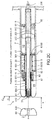
- FIGS. Figures 2B and 2C The interruption position of a single interrupting chamber of an HVDC bypass switch according to the invention is shown in FIGS. Figures 2B and 2C .
- the current to be cut is relatively low since up to 100A or even 1000A.
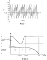
- FIG. 1 is shown the representative curve of the voltage of an HVDC system likely to be present at the terminals of an HVDC bypass switch according to the invention once the interruption of the current carried out.
- the current flowing through the switch has a similar periodicity.
- the inventors propose a new kinematic of a cutoff chamber for the removal of the blast nozzle from the insulating space between fumes in a dielectrically unconstrained area only when any arc has been cut.
- the blowing nozzle must remain substantially in place in its confinement position for the duration of an opening maneuver, which makes it possible to ensure that any arc has been cut.
- the breaking chamber 1 according to the invention shown in FIGS. FIGS. 2A to 2C extends along a longitudinal axis XX 'and is filled with an insulating gas, such as SF6, nitrogen, CF4 or CO2 or a SF6 + nitrogen mixture ...
- the chamber 1 comprises all firstly a single pair of contacts 2, 3.
- One of the contacts 2 is fixed and has a solid rod shape.
- the other of the contacts 3 is movable along the axis XX 'and has a tulip shape. More exactly, the movable contact 3 comprises a tube internally hollow 30 coupled directly to an actuating rod in translation at a fastener 300. At the free end, the tube 30 is connected to the actual contact part 31 in the form of a tulip of inner shapes complementary to those 2.
- the hollow tube 30 also has a narrowing of external shapes by defining a shoulder 301.
- a flange 302 forming a piston (as explained later) is fixed in s' extending radially to the axis XX '.
- the hollow tube is pierced with one or more openings 303 opening at the rear of this flange 302 (that is to say, the side closest to the fastener 300 with the operating rod).
- the hollow tube 30 finally comprises a narrowing 304 of internal diameter or in other words a narrowing of the gas passage section as detailed by the .suite.
- This interrupting chamber 1 further comprises a pair of corona shields 40, 41 whose primary function is to cancel at least reduce the peak effect at the contacts (or the tip of the contacts): level, the electric field tends to tend to infinity, which can contribute to the ionization of the gas and thus the initiation of a possible electric arc.
- the respective endpieces 400, 410 of each cap delimiting circular openings and are spaced a fixed distance e.
- the fixed bow rod 2 is arranged in the circular opening of the endpiece 400, while the movable contact in the form of a tulip 3, 30 and 31 is arranged in the circular opening of the other endpiece 410 regardless of its position ( Figures 2A to 2c ).
- the interrupting chamber also comprises an arc-blowing nozzle 5 of insulating material of tubular general shape and movable in translation along the longitudinal axis XX '.
- the inner diameter 0 of the nozzle 5 is preferably adjusted to the outer diameter of the hollow tube 30 of the movable contact 3.
- the radial height, ie the outside diameter of the tubular nozzle 5 is advantageously chosen in a minimal manner to achieve effective dielectric confinement and ensuring optimum dielectric coordination between corona shields 40, 41 and electrical contacts 2, 3.
- the nozzle 5 is integral with a piston member 6 which is slidably mounted around the movable contact 3, 30 away from the latter and in a fixed part 7 constituting the contact holder.
- the piston 6 comprises a tubular portion 60 hollow internally with several different diameters in continuity with one another.
- An end 600 of this piston tube 60 has an inside diameter for the inner fixing of the nozzle 5 and a guide of the hollow tube 30 of the movable contact 3 when sliding inside.
- the other end 601 of the piston tube 60 has a diameter greater than that of the hollow tube 30 of the moving contact by delimiting a space whose function will be described later.
- This end 601 is integral with the head portion 61 of the piston 6 and is pierced with at least one through hole 6010.
- the head 61 of the piston 6 has an internal diameter for guiding the hollow tube 30 of the movable contact 3 and is pierced with another opening hole 6100.
- the two holes opening 6010 and 6100 can communicate with each other by the volume defined by the remote arrangement of the hollow tube 30 with the end 601 of the tube of diameter greater than the end 600 supporting the tubular nozzle 5.
- the head 61 of the piston 6 is moreover shaped to make a mechanical stop with the shoulder 301 of the tube 3.
- the contact holder 7 is of homothetic internal shapes with those outside the piston 6 to allow their relative sliding with interlocking. Seals 67 are provided between the piston and the contact holder 7. Between the piston 6 and the contact holder 7 is defined a variable volume V1 of insulating gas which accommodates a compression spring 8 constituted by a coil spring whose turns are wound around the tube portion 60, 600, 601 as explained later.
- the function of this compression spring 8 is the return of the piston 6 and thus of the nozzle 5 secured to the latter between its confinement position ( Figures 2A and 2B ) to its withdrawal position ( Figure 2C ), when no mechanical force by mechanical stop between said piston 6 and the shoulder 301 of the hollow tube 30 or a pneumatic force of the insulating gas prevailing in the chamber oppose it.
- the helical spring 8 advantageously has in the illustrated embodiment an end in permanent support against the bottom 70 of liner 7 and the other end also in permanent support against the head 61 of the piston 6 regardless of the relative position of the latter in the contact door ( FIGS. 2A to 2C ).
- the hollow tube 30 of the movable contact 3 is mounted in the contact holder 7 so that the piston flange 302 is guided as tightly as possible inside said sleeve 7. Even if this is not shown, this flange piston 302 houses at its periphery an electrical contact in the form of a metal braid or sliding type. This contact ensures the passage of electric current from the terminal to which the switch is connected by the liner 7 and to the movable contact 3 in the form of a tulip.
- an electrical contact is chosen which is flexible because it does not have to provide mechanical guiding of the tube 30.
- variable volume V2 of insulating gas At the rear of the piston head 61, that is to say between the piston head 61 and the piston flange 302 is defined a variable volume V2 of insulating gas.
- a ring 9 which also guides in the most tight manner possible the hollow tube 30.
- the mechanical guide points of the contact tube 30 are made by the inner diameter of the joke 9 and the piston head 61.
- the piston tube 60 is mechanically guided by the segments 67 also ensuring the sealing function
- valves 91, 92 On the ring 9 are mounted two valves 91, 92. Each valve consists of a plate bearing against the ring 9 at a channel opening. One of the valves 91 has the function, when it is open, of allowing the volume V3 to be filled by the insulating gas coming from the rear of the ring 9, that is to say on the fastener side 300. The other function of the valves 92 is, when open to allow the unloading of a portion of the gas present in the volume V3 as explained later.
- the setting springs of the pads 91, 92 against the ring 9 are not shown in FIG. Figures 2A, 2B , 2C . Only the pin or pin 910 for deflection of the filling valve 91 is represented in FIG. FIGS. 2A to 2C .
- the horn cover 41 arranged around the movable contact 3 regardless of its position is fixed to the contact holder 7 by defining, to the pneumatic leakage of insulating gas near between the piston 6 or the tubular nozzle 5 and the nozzle 410, a volume of substantially fixed insulating gas V4.
- the contact carrier 7 is pierced with a channel 71 opening on the one hand on the variable volume V1 in which is housed the piston 6 and secondly on the volume V4 delimited by the corona cover 41 and the contact holder 7 to which it is attached.
- a non-return valve 10 On this outlet channel 71 is mounted a non-return valve 10 so as to evacuate the insulating gas present in the volume V1 to the volume V4 as explained below.
- the non-return valve 10 consists of a plate bearing against the contact holder 7 at the opening channel 71 via a set of three identical pins 11 and arranged at 120 ° from each other when no gas from V1 exerts pressure.
- the support of the plate 10 against the contact holder 7 is made by weakly calibrated springs surrounded individually around each rod.
- the piston flange 302 then reduces the volume V3 and there is shown a pressure of the gas volume which extends from the ring 9 to the internal narrowing 304 of the hollow tube 30 of the movable contacts 3, that is to say ie, corresponding substantially to the initial volume V3 (from the space between the piston flange 302 and the ring 9 fixed in the contact holder 7 to the inner volume of the hollow tube 30, that is to say until the shrinkage of gas passage section 304 through the inside of the tube 30).
- the arrows referenced GI in Figure 2B indicate the passage of the insulating gas which rises in pressure from the volume V3 which is reduced to the narrowing 304 of passage section in the hollow tube 30.
- the choice of the location of the passage section narrowing 304 and the pressure in the volume V3 are judiciously chosen. Indeed, the inventors started from the observation that a decrease in the density of the insulating gas was harmful insofar as the dielectric strength decreases with the density of gas. However, during an opening maneuver the blowing volume to the smallest gas passage section increases in pressure. However, at the outlet of this volume, if the overpressure exceeds a critical value there may be a drop in gas density, that is to say from the smallest section of gas passage. If this decrease is too important and it occurs at the level of the actual contact part 31 (tulip), the dielectric withstand of the latter at the transient recovery voltage (TTR) immediately after the interruption of the current may not be ensured. Indeed, the electrical gradients after cutting that take place in this portion tulip 31 are particularly high.
- This narrowing 304 is of flow section smaller than that of the tulip and may be an integral part of the hollow tube 304 or be constituted by a piece reported for example by screwing at the end of hollow tube.
- the critical pressure not to be exceeded according to the invention is that to which, despite the implantation of the narrowing 304 upstream of the tulip 31, a low gas density zone could be established between the narrowing 304 and the immediately in the vicinity of the end of the tulip 31.
- the relief valve 92 is thus adjusted so that it opens to its maximum at the critical pressure and therefore, under these conditions , the low density value of the gas is limited in the dielectrically stressed zone.
- the load shedding valve 92 has in the application according to the invention, namely the interruption in bypass HVDC, an additional function. Indeed, during a maneuver opening of a bypass switch HVDC provided with a chamber according to the invention and in the event of a switching fault, the power thyristors equipping the HVDC current conversion substation, a current arc of the order of a few tens of kA may appear between the arcing contacts 2, 3. A rise in pressure can then occur in the space e and by therefore, in the volume V3 in a direction opposite to the direction of blow (that is to say from left to right on the FIGS. 2A to 2C ). The extreme risk of this rise in pressure is therefore an unexpected closure of the contacts 2,3. To avoid this reclosing, the relief valve 92 must be calibrated to be opened early enough during the opening maneuver and therefore open at a relatively low pressure.
- the pneumatic leaks present between the piston 6 and the contact holder 7 on the one hand and the nonreturn valve 10 and the contact holder 7 on the other hand can then act and recess in a position slightly offset from its original position of the Figure 2A .
- the pressure prevailing in the volume V2 compensates for the thrust force of the compressed spring 8 against the piston 6, 61 for a determined lapse of time ⁇ T beyond the time T1 set to reach the open position of the contacts 2, 3.
- the pressure in the volume V2 remains unchanged and substantially equal to the insulating gas filling pressure of the entire switch including the interrupting chamber.
- one or more opening holes are formed in the contact holder 7, which allows a balancing of the pressures between the volume V2 and the rest of the filling volume of the high voltage apparatus provided with the chamber cut.
- the shoulder 301 abuts against the piston head 61 and the spring 8 is compressed: the gas present in the volume V1 is discharged via the channel opening 71 and the non-return valve 10.
- the piston 6 thus moves slowly until the hole 6010 has passed the place where the seal 67 is arranged.
- the pressure p1 then becomes equal to the pressure p2, there are no more pressure forces which oppose to the spring force of the spring 8: the piston 6 accelerates strongly and moves until it abuts against the shoulder 301.
- FIG. 3 there is shown for a breaking chamber 1 according to the FIGS. 2A to 2C , the respective translation strokes of the movable contact 3 and the tubular nozzle 5.
- T1 duration of about 100 ms
- a slight withdrawal of the nozzle 5 once the displacement of the contact 3 started (passage from the confinement position C to C0) until the balance of the forces of pressure on either side of the head 61 of the piston 6 that constitute the spring 8 and the pressures p1 and p2 respectively prevailing in the volumes V1 and V2.
- the nozzle 5 is removed simply because of pneumatic leakage, at a slow speed (about 1 cm / s): the nozzle 5 thus remains substantially close to its confinement position C, C 0 in which allows the gas polluted by arc extinction (s) to be confined and discharged outside the electrical contact zone.
- the hole 6010 of the tube 60 passes below one of the seals 67 interposed between the piston tube 60 and the jacket 7 to reach a position corresponding to a position slightly to the right of that represented in figure 2b .
- the seal 67 under which the hole 6010 passes is the leftmost one on the Figures 2A, 2B and 2C ; it is also smaller in diameter than the one on the right in these figures.
- the seal 67 shown furthest to the right is the one that seals at the level of the piston head 61.
- this mechanical thrust by the spring 8 makes it possible to reach the withdrawal position R of the tubular nozzle 5 very quickly.
- This also enables the HVDC control system to go up to full voltage more quickly, typically at least 400 kVDC for a chamber. according to the invention.
- a closing maneuver takes place in a strictly symmetrical manner ( FIG. 2C to FIG. 2A ).
- a thrust of the hollow tube 30 of the movable contact is made by the operating rod, which also pushes synchronously by mechanical stop 301, 61 the piston 6 blowing nozzle support 5.
- This maneuver compresses the gas present in the volume V1 which escapes through the nonreturn valve 10 in the volume V4.
- the volume V1 is reduced to just necessary to accommodate the return spring 8 in position of the piston 6 and the nozzle 5 it supports.
- the interrupting chamber allows by pneumatic delay of the piston supporting the nozzle (that is to say a maintenance of the nozzle substantially of the nozzle in its confinement position C) to achieve a time ⁇ T of the order of 50ms.
- a time ⁇ T of the order of 50ms.
- Those skilled in the art will easily adapt this latency of movement of the nozzle 5 once the open position reached according to the needs and in particular according to the technological means of verifying the effective breaking of the current.
- the lapse of time will be determined in such a way that it can be ascertained by ad hoc means that the current has not possibly been cut and to close the HVDC bypass switch equipped with the breaking chamber according to the 'invention.
- the shrinkage 304 of the passage section of the insulating gas allowing the pressure rise of the insulating gas during the opening from the inside of the hollow tube 30 is provided substantially close to the connection between the hollow tube 30 and the tulip contact part 3 itself, that is to say the part of complementary shapes with the fixed arc contact rod 2.
- the covers corona represented generally have a cylindrical shape with their tips bent internally delimiting a circular opening in which the tubular nozzle according to the invention is slidably mounted closer to the diameter of said opening.
- Other geometrical shapes of screeds are quite conceivable: the insulating space of length e delimited between these covers of other shapes must be sufficient and the blowing nozzle must be able to be moved from a confinement position in which it confines the gas in an area dielectrically constrained to its retracted position in which it is removed from this space.
- the illustrated embodiment represents a breaking chamber with a single moving contact (the tulip contact 3) it is quite possible to envisage carrying out the invention with a double movement of the contacts, it is that is to say make them separable mutually in the breaking chamber.
- the assembly adopted in the embodiment illustrated for the nonreturn valve 10 is made by a system of pins-spring bearing a ring against the contact door, it can also be considered to simplify the assembly when the chamber cutoff according to the invention must be arranged vertically, to place only a ring on the channel opening, the return of its open position to its position in support against the door contact of the ring is then made by fallout by gravity.
Landscapes
- Circuit Breakers (AREA)
Claims (17)
- Schaltkammer (1), die sich in einer Längsachse (XX') erstreckt und enthält:- ein einziges Paar von Kontaktstücken (2, 3), von denen zumindest eines (3) durch die Einwirkung eines Betätigungsstifts translatorisch in der Längsachse (XX') verschiebbar ist,- eine isolierende Lichtbogenlöschdüse (5) in Röhrenform, die auch translatorisch in der Längsachse (XX') verschiebbar ist,- wobei das/die bewegliche(n) Kontaktstück(e) und die rohrförmige Düse (5) unabhängig voneinander beweglich sind,- wobei die Schaltkammer dadurch gekennzeichnet ist, dass- ein Paar von Entladungsschutzkappen (40, 41), die mit ihren jeweiligen Endstücken (400, 410) um einen gegebenen, festen Abstand e in der Längsachse (XX') voneinander getrennt angeordnet sind und dabei einen Isolierraum definieren und einzeln um jedes der Kontaktstücke des einzigen Kontaktpaares angeordnet sind, und zwar unabhängig von ihrer Position, und wobei das/die bewegliche(n) Kontaktstück(e) und die rohrförmige Düse (5) unabhängig voneinander beweglich sind, so dass :- in der Schließstellung der Kontaktstücke die rohrförmige Düse in einer sogenannten Umhüllungsposition (C) ist, in welcher sie sich zumindest in dem Isolierraum mit der Länge e zwischen den Kontaktstücken (2, 3) und den Endstücken (400, 410) der Entladungschutzkappen (40, 41) erstreckt,- während einer Öffnungsbetätigung die rohrförmige Düse (5) im Wesentlichen in ihrer Umhüllungsposition gehalten bleibt, zumindest solange, bis das/die bewegliche(n) Kontaktstück(e) die Öffnungsposition (O) erreicht hat/haben,- nach erfolgter Öffnungsbetätigung und Stromabschaltung die rohrförmige Düse (5) in eine sogenannte Rückzugsposition (R) verlagert wird, in welcher sie von dem Isolierraum zurückgezogen ist,in welcher die Düse während einer Öffnungsbetätigung durch pneumatische Schubkraft des Isoliergases aus der Kammer auf die Düse in ihrer Umhüllungsposition gehalten wird.
- Schaltkammer (1) nach Anspruch 1, wobei die pneumatische Schubkraft auf ein fest mit der Düse (5) verbundenes und als Kolben ausgebildetes Teil (6) aufgebracht wird, wobei der Kolben (6) um eines der beweglichen Kontaktstücke (3, 30) herum in einem festen Teil (7) gleitbeweglich gelagert ist, das den Kontaktträger bildet.
- Schaltkammer (1) nach einem der Ansprüche 1 oder 2, wobei die Verlagerung der Düse (5) in ihre vom Isolierraum zurückgezogene Position (R) nach einem bestimmten Zeitraum bezogen auf den Zeitpunkt des vollständigen Öffnens der Kontaktstücke (2, 3) erfolgt.
- Schaltkammer (1) nach Anspruch 3, wobei der Zeitraum so bestimmt ist, dass eine Schließbetätigung des/der beweglichen Kontaktstücks / Kontaktstücke (3) dann durchgeführt werden kann, wenn die Düse (5) in ihrer Umhüllungsposition (C) gehalten wird und weiterhin ein abzuschaltender Strom besteht.
- Schaltkammer (1) nach Anspruch 4, wobei der Zeitraum in der Größenordnung von 100 ms liegt.
- Schaltkammer (1) nach einem der Ansprüche 3 bis 5, wobei die Verlagerung der Düse in ihre vom Isolierraum zurückgezogene Position über eine Druckfeder (8) erfolgt, von welcher ein Ende fest und das andere mit einem Teil (6) verbunden ist, das seinerseits fest mit der beweglichen Düse (5) verbunden ist, wobei das Entspannen der Feder (8) bis in die Rückzugsposition (R) der Düse (5) nach dem bestimmten Zeitraum erfolgt.
- Schaltkammer (1) nach einem der Ansprüche 2 bis 6, wobei die Druckfeder (8) in einem veränderlichen Raumvolumen V1 angeordnet ist, das zwischen dem Kolben (6) und dem Kontaktträger (7) definiert ist.
- Schaltkammer (1) nach Anspruch 7, wobei eines der beweglichen Kontaktstücke (3, 30) eine Schulter (301) aufweist und wobei der Kontaktträger (7) im Bereich des Raumvolums V1 einen durchgehenden Kanal (71) aufweist, an dem ein Rückschlagventil (10) angebracht ist, wobei das in dem Raumvolumen V1 vorhandene Isoliergas- bei einer Schließbetätigung unter der Wirkung des Kolbens (6) in mechanischem Anschlag an der Schulter (301) des beweglichen Kontaktstücks (3) durch den Kanal (71) und das Rückschlagventil (10) in freigegebener Position des Kanals abgeleitet wird, so dass das Raumvolumen V1 auf das Minimum vermindert wird, um die Feder im zusammengedrückten Zustand aufzunehmen,- bei einer Öffnungsbetätigung zumindest für den bestimmten Zeitraum und bis auf Druckluftlecks gehalten wird, die zwischen dem Kolben und dem Kontaktträger einerseits und zwischen dem Rückschlagventil und dem Kontaktträger andererseits vorhanden sind, und zwar unter der Wirkung des herrschenden Drucks in einem Raumvolumen V2, das zwischen dem Kontaktträger (7) und dem beweglichen Kontaktstück (3) auf der Kolbenseite definiert ist, die derjenigen entgegengesetzt ist, wo die Feder angeordnet ist, wobei mit der Druckdifferenz zwischen diesen in den Raumvolumina V1 und V1 herrschenden Druckwerten die Schubkraft der zusammengedrückten Feder (8) gegen den Kolben (6, 61) für den bestimmten Zeitraum kompensiert wird.
- Schaltkammer (1) nach Anspruch 8, wobei- der Rohrabschnitt (60, 601) des Kolbens (6), der dessen Kopf (61) mit der Düse (5) verbindet, im Abstand von dem beweglichen Kontaktstück angeordnet ist und eine Durchgangslochung (6010) aufweist,- der Kopfabschnitt (61) des Kolbens zwischen dem beweglichen Kontakt (3) und dem Rohr (60, 601) des Kolbens eine weitere Durchgangslochung (6100) zwischen den Raumvolumina V1 und V2 aufweist, wobei die Durchgangslochung (6010) des Kolbenrohrs (60) so angeordnet ist, dass nach dem bestimmten Zeitraum der Kolben (6) aufgrund von Druckluftlecks in eine Position gebracht wird, in der es dem Gas aus dem Raumvolumen V2 möglich ist, über die Durchgangslochungen (6010, 6100) in das Raumvolumen V1 einzuströmen, wodurch die Verlagerung der fest mit dem Kolben (6) verbunden Düse (5) in ihre Rückzugsposition beschleunigt wird.
- Schaltkammer nach einem der vorangehenden Ansprüche, wobei die beiden Kontaktstücke beweglich sind und Übertragungseinrichtungen zwischen den Kontaktstücken zum gegenseitigen Trennen der Kontaktstücke in der Schaltkammer vorgesehen sind.
- Hochspannungsschalter mit einer Schaltkammer nach einem der vorangehenden Ansprüche.
- Schalter nach Anspruch 11, wobei er einen Leistungsschalter oder einen Sammelschienen-Trennschalter oder einen Erdungstrenner bildet.
- Schalter mit einer Schaltkammer (1) nach einem der vorangehenden Ansprüche, wobei er einen HVDC-Bypass-Schalter bildet.
- HVDC-Bypass-Schalter nach Anspruch 13, enthaltend eine einzige Schaltkammer (1).
- HVDC-Schalter nach Anspruch 14, wobei der mit der Kammer abzuschaltende Strom bis zu mehrere 100 A bzw. 1000 A erreichen kann und die mit der Kammer zu haltende Spannung zumindest 400 kV bei Gleichstrom (CC) erreichen kann.
- HVDC-Umwandlungs-Unterstation, enthaltend zumindest einen HVDC-Bypass-Schalter nach einem der Ansprüche 13 bis 15.
- HVDC-Umwandlungs-Unterstation nach Anspruch 16, wobei die Achse der Schaltkammer des Schalters im Wesentlichen vertikal verläuft.
Applications Claiming Priority (1)
| Application Number | Priority Date | Filing Date | Title |
|---|---|---|---|
| FR0952173A FR2944135B1 (fr) | 2009-04-03 | 2009-04-03 | Chambre de coupure de courant a contact mobile et buse de soufflage mobile manoeuvres independamment, interrupteur by pass hvdc et sous station de conversion hvdc comprenant une telle chambre. |
Publications (2)
| Publication Number | Publication Date |
|---|---|
| EP2237301A1 EP2237301A1 (de) | 2010-10-06 |
| EP2237301B1 true EP2237301B1 (de) | 2016-08-17 |
Family
ID=41128266
Family Applications (1)
| Application Number | Title | Priority Date | Filing Date |
|---|---|---|---|
| EP10158757.4A Active EP2237301B1 (de) | 2009-04-03 | 2010-03-31 | Schaltkammer mit beweglichem Kontakt und unabhängig davon beweglicher Blasdüse, Bypass HVDC Leistungsschalter und Substation mit HVDC Wandler mit einer solchen Schaltkammer |
Country Status (3)
| Country | Link |
|---|---|
| EP (1) | EP2237301B1 (de) |
| CN (1) | CN101901721B (de) |
| FR (1) | FR2944135B1 (de) |
Families Citing this family (2)
| Publication number | Priority date | Publication date | Assignee | Title |
|---|---|---|---|---|
| FR2989013B1 (fr) * | 2012-04-04 | 2014-04-11 | Air Liquide | Buse laser avec element mobile a profil externe ameliore |
| EP3361488A1 (de) | 2017-02-14 | 2018-08-15 | General Electric Technology GmbH | Bypass-schalter und bypass-verfahren |
Family Cites Families (6)
| Publication number | Priority date | Publication date | Assignee | Title |
|---|---|---|---|---|
| DE829916C (de) * | 1949-04-12 | 1952-01-31 | August Hofmann | Fluessigkeitsschalter |
| DE928534C (de) * | 1952-08-23 | 1955-06-02 | Licentia Gmbh | Elektrischer Schalter mit einem stroemenden Medium als Loeschmittel |
| US3914569A (en) * | 1974-05-02 | 1975-10-21 | Ite Imperial Corp | Puffer interrupter with downstream initiated arc |
| SE417880B (sv) * | 1977-02-28 | 1981-04-13 | Licentia Gmbh | Autopneumatisk tryckgas-effektbrytare |
| JPS63211532A (ja) * | 1987-02-26 | 1988-09-02 | 三菱電機株式会社 | ガス開閉器 |
| CN101297469B (zh) | 2006-01-18 | 2011-05-11 | Abb技术有限公司 | 传输系统及其控制方法 |
-
2009
- 2009-04-03 FR FR0952173A patent/FR2944135B1/fr active Active
-
2010
- 2010-03-31 EP EP10158757.4A patent/EP2237301B1/de active Active
- 2010-04-02 CN CN201010156562.7A patent/CN101901721B/zh not_active Expired - Fee Related
Also Published As
| Publication number | Publication date |
|---|---|
| FR2944135A1 (fr) | 2010-10-08 |
| CN101901721A (zh) | 2010-12-01 |
| EP2237301A1 (de) | 2010-10-06 |
| CN101901721B (zh) | 2015-01-07 |
| FR2944135B1 (fr) | 2011-06-10 |
Similar Documents
| Publication | Publication Date | Title |
|---|---|---|
| EP1271590B1 (de) | Hybridleistungsschalter für Hoch- oder Mittelspannung mit Vakuum und Gas | |
| EP1369888B1 (de) | Hybridleistungsschalter für Hoch- oder Mittelspannung mit Vakuum und Gas | |
| EP1580783B1 (de) | Steuervorrichtung für die coordinierte Betätigung mindestens zweier Schaltgeräte, wovon eines ein Vakuumschalter ist | |
| EP2402969B1 (de) | Unterbrechungskammer eines Schutzschalters für Hoch- und Mittelspannung mit reduzierter Bedienungsenergie | |
| EP1583124B1 (de) | Hybrider Hochspannungsschutzschalter | |
| EP2237301A1 (de) | Schaltkammer mit beweglichem Kontakt und unabhängig davon beweglicher Blasdüse, Bypass HVDC Leistungsschalter und Substation mit HVDC Wandler mit einer solchen Schaltkammer | |
| FR2748597A1 (fr) | Disjoncteur a haute tension avec insertion de resistance a la fermeture | |
| EP2237300B1 (de) | Schaltkammer mit beweglichem Kontakt und Lichtbogenbeblasung darin, Bypass-HVDC Leistungsschalter und Substation mit HVDC-Wandler mit einer solchen Schaltkammer | |
| EP3073504B1 (de) | Unterbrechungsschalter für ein dreiphasennetz | |
| EP3251140B1 (de) | Schutzschalter mit ausziehbarer auslassabdeckung | |
| EP0759629B1 (de) | Lastschalter mit Einschaltwiderstand und Einfügungsvorrichtung | |
| EP0785562A1 (de) | Lastschalter mit Kontakten mit Doppelbewegung | |
| EP0456025B1 (de) | Hochspannungsschalter mit Hilfslichtbogen in Reihe | |
| EP2402970B1 (de) | Unterbrechungskammer eines Schutzschalters für Hoch- und Mittelspannung mit reduzierter Bedienungsenergie und kleineren Abmessungen | |
| EP2735012B1 (de) | Trennschalter für eine gasisolierte anlage mit einer vakuumröhre | |
| FR3003078A1 (fr) | Disjoncteur ht avec dispositif de regeneration des contacts electriques en bout | |
| FR2949170A1 (fr) | Chambre de coupure pour disjoncteur a moyenne ou haute tension a energie de manœuvre reduite | |
| FR2839193A1 (fr) | Dispositif interrupteur a haute tension a coupure mixte par vide et gaz | |
| CH688702A5 (fr) | Disjoncteur à haute tension ayant une chambre de coupure à volume de soufflage variable. | |
| CH689473A5 (fr) | Disjoncteur à grande tension d'arc. | |
| FR2737937A1 (fr) | Disjoncteur a double mouvement avec resistance de fermeture | |
| EP3142134A1 (de) | Assistenzsystem zur detektion einer störung eines trennschalters, das an mittel- und hochspannungen angepasst ist | |
| FR2705494A1 (fr) | Disjoncteur à manÓoeuvre assistée par voie électrodynamique. |
Legal Events
| Date | Code | Title | Description |
|---|---|---|---|
| PUAI | Public reference made under article 153(3) epc to a published international application that has entered the european phase |
Free format text: ORIGINAL CODE: 0009012 |
|
| AK | Designated contracting states |
Kind code of ref document: A1 Designated state(s): AT BE BG CH CY CZ DE DK EE ES FI FR GB GR HR HU IE IS IT LI LT LU LV MC MK MT NL NO PL PT RO SE SI SK SM TR |
|
| AX | Request for extension of the european patent |
Extension state: AL BA ME RS |
|
| 17P | Request for examination filed |
Effective date: 20110324 |
|
| RAP1 | Party data changed (applicant data changed or rights of an application transferred) |
Owner name: ALSTOM GRID SAS |
|
| RAP1 | Party data changed (applicant data changed or rights of an application transferred) |
Owner name: ALSTOM TECHNOLOGY LTD |
|
| GRAP | Despatch of communication of intention to grant a patent |
Free format text: ORIGINAL CODE: EPIDOSNIGR1 |
|
| INTG | Intention to grant announced |
Effective date: 20160315 |
|
| RAP1 | Party data changed (applicant data changed or rights of an application transferred) |
Owner name: GENERAL ELECTRIC TECHNOLOGY GMBH |
|
| GRAS | Grant fee paid |
Free format text: ORIGINAL CODE: EPIDOSNIGR3 |
|
| GRAA | (expected) grant |
Free format text: ORIGINAL CODE: 0009210 |
|
| AK | Designated contracting states |
Kind code of ref document: B1 Designated state(s): AT BE BG CH CY CZ DE DK EE ES FI FR GB GR HR HU IE IS IT LI LT LU LV MC MK MT NL NO PL PT RO SE SI SK SM TR |
|
| REG | Reference to a national code |
Ref country code: GB Ref legal event code: FG4D Free format text: NOT ENGLISH |
|
| REG | Reference to a national code |
Ref country code: CH Ref legal event code: EP Ref country code: CH Ref legal event code: NV Representative=s name: BOVARD AG, CH |
|
| REG | Reference to a national code |
Ref country code: IE Ref legal event code: FG4D Free format text: LANGUAGE OF EP DOCUMENT: FRENCH |
|
| REG | Reference to a national code |
Ref country code: AT Ref legal event code: REF Ref document number: 821779 Country of ref document: AT Kind code of ref document: T Effective date: 20160915 |
|
| REG | Reference to a national code |
Ref country code: DE Ref legal event code: R096 Ref document number: 602010035530 Country of ref document: DE |
|
| REG | Reference to a national code |
Ref country code: SE Ref legal event code: TRGR |
|
| REG | Reference to a national code |
Ref country code: NL Ref legal event code: MP Effective date: 20160817 |
|
| REG | Reference to a national code |
Ref country code: LT Ref legal event code: MG4D |
|
| REG | Reference to a national code |
Ref country code: AT Ref legal event code: MK05 Ref document number: 821779 Country of ref document: AT Kind code of ref document: T Effective date: 20160817 |
|
| PG25 | Lapsed in a contracting state [announced via postgrant information from national office to epo] |
Ref country code: IT Free format text: LAPSE BECAUSE OF FAILURE TO SUBMIT A TRANSLATION OF THE DESCRIPTION OR TO PAY THE FEE WITHIN THE PRESCRIBED TIME-LIMIT Effective date: 20160817 Ref country code: FI Free format text: LAPSE BECAUSE OF FAILURE TO SUBMIT A TRANSLATION OF THE DESCRIPTION OR TO PAY THE FEE WITHIN THE PRESCRIBED TIME-LIMIT Effective date: 20160817 Ref country code: HR Free format text: LAPSE BECAUSE OF FAILURE TO SUBMIT A TRANSLATION OF THE DESCRIPTION OR TO PAY THE FEE WITHIN THE PRESCRIBED TIME-LIMIT Effective date: 20160817 Ref country code: LT Free format text: LAPSE BECAUSE OF FAILURE TO SUBMIT A TRANSLATION OF THE DESCRIPTION OR TO PAY THE FEE WITHIN THE PRESCRIBED TIME-LIMIT Effective date: 20160817 Ref country code: NO Free format text: LAPSE BECAUSE OF FAILURE TO SUBMIT A TRANSLATION OF THE DESCRIPTION OR TO PAY THE FEE WITHIN THE PRESCRIBED TIME-LIMIT Effective date: 20161117 Ref country code: NL Free format text: LAPSE BECAUSE OF FAILURE TO SUBMIT A TRANSLATION OF THE DESCRIPTION OR TO PAY THE FEE WITHIN THE PRESCRIBED TIME-LIMIT Effective date: 20160817 |
|
| PG25 | Lapsed in a contracting state [announced via postgrant information from national office to epo] |
Ref country code: PL Free format text: LAPSE BECAUSE OF FAILURE TO SUBMIT A TRANSLATION OF THE DESCRIPTION OR TO PAY THE FEE WITHIN THE PRESCRIBED TIME-LIMIT Effective date: 20160817 Ref country code: PT Free format text: LAPSE BECAUSE OF FAILURE TO SUBMIT A TRANSLATION OF THE DESCRIPTION OR TO PAY THE FEE WITHIN THE PRESCRIBED TIME-LIMIT Effective date: 20161219 Ref country code: LV Free format text: LAPSE BECAUSE OF FAILURE TO SUBMIT A TRANSLATION OF THE DESCRIPTION OR TO PAY THE FEE WITHIN THE PRESCRIBED TIME-LIMIT Effective date: 20160817 Ref country code: GR Free format text: LAPSE BECAUSE OF FAILURE TO SUBMIT A TRANSLATION OF THE DESCRIPTION OR TO PAY THE FEE WITHIN THE PRESCRIBED TIME-LIMIT Effective date: 20161118 Ref country code: ES Free format text: LAPSE BECAUSE OF FAILURE TO SUBMIT A TRANSLATION OF THE DESCRIPTION OR TO PAY THE FEE WITHIN THE PRESCRIBED TIME-LIMIT Effective date: 20160817 Ref country code: AT Free format text: LAPSE BECAUSE OF FAILURE TO SUBMIT A TRANSLATION OF THE DESCRIPTION OR TO PAY THE FEE WITHIN THE PRESCRIBED TIME-LIMIT Effective date: 20160817 |
|
| REG | Reference to a national code |
Ref country code: FR Ref legal event code: PLFP Year of fee payment: 8 |
|
| PG25 | Lapsed in a contracting state [announced via postgrant information from national office to epo] |
Ref country code: EE Free format text: LAPSE BECAUSE OF FAILURE TO SUBMIT A TRANSLATION OF THE DESCRIPTION OR TO PAY THE FEE WITHIN THE PRESCRIBED TIME-LIMIT Effective date: 20160817 Ref country code: RO Free format text: LAPSE BECAUSE OF FAILURE TO SUBMIT A TRANSLATION OF THE DESCRIPTION OR TO PAY THE FEE WITHIN THE PRESCRIBED TIME-LIMIT Effective date: 20160817 |
|
| PGFP | Annual fee paid to national office [announced via postgrant information from national office to epo] |
Ref country code: FR Payment date: 20170327 Year of fee payment: 8 |
|
| REG | Reference to a national code |
Ref country code: DE Ref legal event code: R097 Ref document number: 602010035530 Country of ref document: DE |
|
| PG25 | Lapsed in a contracting state [announced via postgrant information from national office to epo] |
Ref country code: DK Free format text: LAPSE BECAUSE OF FAILURE TO SUBMIT A TRANSLATION OF THE DESCRIPTION OR TO PAY THE FEE WITHIN THE PRESCRIBED TIME-LIMIT Effective date: 20160817 Ref country code: BG Free format text: LAPSE BECAUSE OF FAILURE TO SUBMIT A TRANSLATION OF THE DESCRIPTION OR TO PAY THE FEE WITHIN THE PRESCRIBED TIME-LIMIT Effective date: 20161117 Ref country code: SM Free format text: LAPSE BECAUSE OF FAILURE TO SUBMIT A TRANSLATION OF THE DESCRIPTION OR TO PAY THE FEE WITHIN THE PRESCRIBED TIME-LIMIT Effective date: 20160817 Ref country code: SK Free format text: LAPSE BECAUSE OF FAILURE TO SUBMIT A TRANSLATION OF THE DESCRIPTION OR TO PAY THE FEE WITHIN THE PRESCRIBED TIME-LIMIT Effective date: 20160817 Ref country code: CZ Free format text: LAPSE BECAUSE OF FAILURE TO SUBMIT A TRANSLATION OF THE DESCRIPTION OR TO PAY THE FEE WITHIN THE PRESCRIBED TIME-LIMIT Effective date: 20160817 |
|
| PLBE | No opposition filed within time limit |
Free format text: ORIGINAL CODE: 0009261 |
|
| STAA | Information on the status of an ep patent application or granted ep patent |
Free format text: STATUS: NO OPPOSITION FILED WITHIN TIME LIMIT |
|
| 26N | No opposition filed |
Effective date: 20170518 |
|
| PG25 | Lapsed in a contracting state [announced via postgrant information from national office to epo] |
Ref country code: SI Free format text: LAPSE BECAUSE OF FAILURE TO SUBMIT A TRANSLATION OF THE DESCRIPTION OR TO PAY THE FEE WITHIN THE PRESCRIBED TIME-LIMIT Effective date: 20160817 |
|
| GBPC | Gb: european patent ceased through non-payment of renewal fee |
Effective date: 20170331 |
|
| PG25 | Lapsed in a contracting state [announced via postgrant information from national office to epo] |
Ref country code: MC Free format text: LAPSE BECAUSE OF FAILURE TO SUBMIT A TRANSLATION OF THE DESCRIPTION OR TO PAY THE FEE WITHIN THE PRESCRIBED TIME-LIMIT Effective date: 20160817 |
|
| REG | Reference to a national code |
Ref country code: IE Ref legal event code: MM4A |
|
| PG25 | Lapsed in a contracting state [announced via postgrant information from national office to epo] |
Ref country code: LU Free format text: LAPSE BECAUSE OF NON-PAYMENT OF DUE FEES Effective date: 20170331 |
|
| PG25 | Lapsed in a contracting state [announced via postgrant information from national office to epo] |
Ref country code: IE Free format text: LAPSE BECAUSE OF NON-PAYMENT OF DUE FEES Effective date: 20170331 Ref country code: GB Free format text: LAPSE BECAUSE OF NON-PAYMENT OF DUE FEES Effective date: 20170331 |
|
| REG | Reference to a national code |
Ref country code: BE Ref legal event code: MM Effective date: 20170331 |
|
| PG25 | Lapsed in a contracting state [announced via postgrant information from national office to epo] |
Ref country code: BE Free format text: LAPSE BECAUSE OF NON-PAYMENT OF DUE FEES Effective date: 20170331 |
|
| PG25 | Lapsed in a contracting state [announced via postgrant information from national office to epo] |
Ref country code: MT Free format text: LAPSE BECAUSE OF FAILURE TO SUBMIT A TRANSLATION OF THE DESCRIPTION OR TO PAY THE FEE WITHIN THE PRESCRIBED TIME-LIMIT Effective date: 20160817 |
|
| PG25 | Lapsed in a contracting state [announced via postgrant information from national office to epo] |
Ref country code: FR Free format text: LAPSE BECAUSE OF NON-PAYMENT OF DUE FEES Effective date: 20180331 |
|
| PG25 | Lapsed in a contracting state [announced via postgrant information from national office to epo] |
Ref country code: HU Free format text: LAPSE BECAUSE OF FAILURE TO SUBMIT A TRANSLATION OF THE DESCRIPTION OR TO PAY THE FEE WITHIN THE PRESCRIBED TIME-LIMIT; INVALID AB INITIO Effective date: 20100331 |
|
| PG25 | Lapsed in a contracting state [announced via postgrant information from national office to epo] |
Ref country code: CY Free format text: LAPSE BECAUSE OF NON-PAYMENT OF DUE FEES Effective date: 20160817 |
|
| PG25 | Lapsed in a contracting state [announced via postgrant information from national office to epo] |
Ref country code: MK Free format text: LAPSE BECAUSE OF FAILURE TO SUBMIT A TRANSLATION OF THE DESCRIPTION OR TO PAY THE FEE WITHIN THE PRESCRIBED TIME-LIMIT Effective date: 20160817 |
|
| PG25 | Lapsed in a contracting state [announced via postgrant information from national office to epo] |
Ref country code: TR Free format text: LAPSE BECAUSE OF FAILURE TO SUBMIT A TRANSLATION OF THE DESCRIPTION OR TO PAY THE FEE WITHIN THE PRESCRIBED TIME-LIMIT Effective date: 20160817 |
|
| PG25 | Lapsed in a contracting state [announced via postgrant information from national office to epo] |
Ref country code: IS Free format text: LAPSE BECAUSE OF FAILURE TO SUBMIT A TRANSLATION OF THE DESCRIPTION OR TO PAY THE FEE WITHIN THE PRESCRIBED TIME-LIMIT Effective date: 20161217 |
|
| P01 | Opt-out of the competence of the unified patent court (upc) registered |
Effective date: 20230522 |
|
| REG | Reference to a national code |
Ref country code: DE Ref legal event code: R082 Ref document number: 602010035530 Country of ref document: DE Representative=s name: KANDLBINDER, MARKUS, DIPL.-PHYS., DE |
|
| PGFP | Annual fee paid to national office [announced via postgrant information from national office to epo] |
Ref country code: CH Payment date: 20250401 Year of fee payment: 16 |
|
| REG | Reference to a national code |
Ref country code: CH Ref legal event code: U11 Free format text: ST27 STATUS EVENT CODE: U-0-0-U10-U11 (AS PROVIDED BY THE NATIONAL OFFICE) Effective date: 20260401 |
|
| PGFP | Annual fee paid to national office [announced via postgrant information from national office to epo] |
Ref country code: SE Payment date: 20260219 Year of fee payment: 17 |
|
| PGFP | Annual fee paid to national office [announced via postgrant information from national office to epo] |
Ref country code: DE Payment date: 20260219 Year of fee payment: 17 |