EP2237587A1 - Système et procédé de radiocommunications, dispositif station de base, et dispositif passerelle - Google Patents
Système et procédé de radiocommunications, dispositif station de base, et dispositif passerelle Download PDFInfo
- Publication number
- EP2237587A1 EP2237587A1 EP08871880A EP08871880A EP2237587A1 EP 2237587 A1 EP2237587 A1 EP 2237587A1 EP 08871880 A EP08871880 A EP 08871880A EP 08871880 A EP08871880 A EP 08871880A EP 2237587 A1 EP2237587 A1 EP 2237587A1
- Authority
- EP
- European Patent Office
- Prior art keywords
- base station
- gateway
- origination
- radio communication
- information
- Prior art date
- Legal status (The legal status is an assumption and is not a legal conclusion. Google has not performed a legal analysis and makes no representation as to the accuracy of the status listed.)
- Withdrawn
Links
- 238000004891 communication Methods 0.000 title claims abstract description 157
- 238000000034 method Methods 0.000 title claims description 93
- 230000005540 biological transmission Effects 0.000 claims description 136
- 230000004044 response Effects 0.000 claims description 60
- 230000008859 change Effects 0.000 claims description 23
- 238000012546 transfer Methods 0.000 claims description 20
- 238000001514 detection method Methods 0.000 claims 2
- 241000760358 Enodes Species 0.000 description 353
- 230000008569 process Effects 0.000 description 61
- 238000010586 diagram Methods 0.000 description 8
- 238000013461 design Methods 0.000 description 5
- 230000000694 effects Effects 0.000 description 5
- 230000006870 function Effects 0.000 description 5
- 230000004075 alteration Effects 0.000 description 4
- 238000009434 installation Methods 0.000 description 4
- 238000005259 measurement Methods 0.000 description 4
- MWRWFPQBGSZWNV-UHFFFAOYSA-N Dinitrosopentamethylenetetramine Chemical compound C1N2CN(N=O)CN1CN(N=O)C2 MWRWFPQBGSZWNV-UHFFFAOYSA-N 0.000 description 3
- 230000035755 proliferation Effects 0.000 description 2
- 230000009467 reduction Effects 0.000 description 2
- 238000012795 verification Methods 0.000 description 2
- 238000013459 approach Methods 0.000 description 1
- 230000003190 augmentative effect Effects 0.000 description 1
- 238000012217 deletion Methods 0.000 description 1
- 230000037430 deletion Effects 0.000 description 1
- 230000007774 longterm Effects 0.000 description 1
- 238000012986 modification Methods 0.000 description 1
- 230000004048 modification Effects 0.000 description 1
- 230000005641 tunneling Effects 0.000 description 1
Images








Classifications
-
- H—ELECTRICITY
- H04—ELECTRIC COMMUNICATION TECHNIQUE
- H04L—TRANSMISSION OF DIGITAL INFORMATION, e.g. TELEGRAPHIC COMMUNICATION
- H04L63/00—Network architectures or network communication protocols for network security
- H04L63/12—Applying verification of the received information
- H04L63/126—Applying verification of the received information the source of the received data
-
- H—ELECTRICITY
- H04—ELECTRIC COMMUNICATION TECHNIQUE
- H04W—WIRELESS COMMUNICATION NETWORKS
- H04W12/00—Security arrangements; Authentication; Protecting privacy or anonymity
- H04W12/10—Integrity
- H04W12/106—Packet or message integrity
-
- H—ELECTRICITY
- H04—ELECTRIC COMMUNICATION TECHNIQUE
- H04W—WIRELESS COMMUNICATION NETWORKS
- H04W36/00—Hand-off or reselection arrangements
- H04W36/0005—Control or signalling for completing the hand-off
- H04W36/0011—Control or signalling for completing the hand-off for data sessions of end-to-end connection
-
- H—ELECTRICITY
- H04—ELECTRIC COMMUNICATION TECHNIQUE
- H04W—WIRELESS COMMUNICATION NETWORKS
- H04W36/00—Hand-off or reselection arrangements
- H04W36/0005—Control or signalling for completing the hand-off
- H04W36/0055—Transmission or use of information for re-establishing the radio link
- H04W36/0061—Transmission or use of information for re-establishing the radio link of neighbour cell information
-
- H—ELECTRICITY
- H04—ELECTRIC COMMUNICATION TECHNIQUE
- H04W—WIRELESS COMMUNICATION NETWORKS
- H04W88/00—Devices specially adapted for wireless communication networks, e.g. terminals, base stations or access point devices
- H04W88/08—Access point devices
Definitions
- the present invention relates to a radio communication system, a base station, a gateway, and a radio communication method.
- EUTRAN Evolved UMTS Terrestrial Radio Access network
- UMTS Universal Mobile Telecommunication System
- EPC Evolved Packet Core
- FIG. 1 LTE (Long Term Evolution) for which standardization is advancing in the 3GPP (3 rd Generation Partnership Projects) (see 4.2.1 of Non-Patent Document 1 and FIG. 4 of Non-Patent Document 2).
- LTE Long Term Evolution
- SAE System Architecture Evolution
- EUTRAN together with EPC being referred to as an EPS (Evolved Packet System).
- EPS Evolved Packet System
- eNode B (evolved Node B) 10, which are base stations, are provided on the EUTRAN side.
- MME Mobility Management Entity
- S-GW Serving Gateway
- P-GW Packet Data Network Gateway
- HSS Home Subscriber Server
- eNode B 10 are connected to UE (User Equipment) 60 that is a radio communication apparatus by way of a radio interface.
- MME 20 is a node equipped with the mobility management (location updating) function and handover control function of UE 60, and the selection function and bearer management function of S-GW 30 and P-GW 40 (4.4.2 of Non-Patent Document 1).
- S-GW 30 is a node that transfers packet data of the user plane between eNode B 10 and P-GW 40.
- P-GW 40 is a node that transfers transmission packet data from its own network (Home PLMN, where PLMN is a Public Land Mobile Network) to an outside network (Visit PLMN) and received packet data from an outside network to its own network.
- HSS 50 is a server that holds user information that is used in the authentication of UE 60.
- S-GW 30 In order to ensure the security of a radio communication system, S-GW 30 must know the origination address of eNode B 10 to verify the safety of uplink packet data from eNode B 10.
- the origination address of eNode B 10 is set in S-GW 30 by the manual operation of an operator beforehand.
- setting by manual operation of an operator is extremely tedious and may entail the problem of an increase in OPEX (Operation Expenditure) when a large number of eNode B 10 are to be installed.
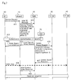
- eNode B 10 of the movement origin of UE 60 at the time of handover is referred to as Source eNode B 10-S and the movement destination of eNode B 10 is referred to as Target eNode B 10-T (identical hereinbelow).
- UE 60 has moved from the area of Source eNode B 10-S to the area of Target eNode B 10-T, whereby Source eNode B 10-S is assumed to have made a handover decision (HO decision) in Step 2301.
- HO decision handover decision
- Source eNode B 10-S then transmits a message (Handover Request message) requesting handover to Target eNode B 10-T in Step 2302.
- Target eNode B 10-T After setting radio resources in Step 2303, Target eNode B 10-T next transmits a response message (Handover Response Message) to the Handover Request message to Source eNode B 10-S in Step 2304.
- Source eNode B 10-S transmits a message (Handover Command message) commanding handover to UE 60.
- UE 60 transmits uplink packet data in Step 2307.
- S-GW 30 receives packet data from Target eNode B 10-T, S-GW 30 does not know the origination address of Target eNode B 10-T and therefore ignores security and, without verifying the origination address of Target eNode B 10-T, transmits the received packet data without alteration to P-GW 40.
- Ignoring security in this way raises the potential for the occurrence of serious problems such as system failures caused by proliferation within the network of illegal packet data that carry the danger of an attack in which the transmission of a large volume of packet data paralyzes the radio communication system and prevents the continuation of service, i.e., the danger of a DoS attack (Denial of Service attack).
- DoS attack Delivery of Service attack
- Target eNode B 10-T transmits a message (Path Switch Request message) requesting path switching to MME 20 in Step 2309, and MME 20 transmits a message (User Plane Update Request message) requesting updating of the user plane to S-GW 30 in Step 2310.
- S-GW 30, having received this message, carries out path switching of downlink from Source eNode B 10-S to Target eNode B 10-T in Step 2311.
- S-GW 30 then transmits a response message (User Plane Update Response message) to the User Plane Update Request message to MME 20 in Step 2312.
- MME 20 transmits a response message (Path Switch Request Acknowledgement message) to the path switch request message to Target eNode B 10-T in Step 2313, and Target eNode B 10-T transmits a message (Release Resource message) indicating the release of resources in Step 2314.
- S-GW 30 the safety of packet data received in S-GW 30 from Target eNode B 10-T must be verified even when handover occurs to ensure the security of a radio communication system, and to this end, S-GW 30 must know the origination address of Target eNode B 10-T.
- setting the origination address of eNode B 10 in S-GW 30 by the manual operation of an operator has the potential of leading to an increase in OPEX.
- eNode B 10, MME 20, and S-GW 30 are provided in the outside network of the roaming destination of UE 60 (Visit PLMN).
- S-GW 30 of the outside network and P-GW 40 of the home network are normally connected by way of a public network.
- the public network is, for example, a public Internet network.
- P-GW 40 must collate the origination address of the packet data that were received from the public network with the origination address of S-GW 30 that transmitted in these packet data, and, after verifying safety, transfer the received packet data into its own network.
- P-GW 40 must know the origination address of S-GW 30, but in the event of handover that accompanies change of S-GW 30 in a roaming environment, P-GW 40 cannot learn the origination address of S-GW 30 after the change.
- ensuring the security of a radio communication system requires the verification of the safety of packet data received in P-GW 40 of the home network from S-GW 30 of the outside network that is the roaming destination of UE 60 even in the event of handover that accompanies change of S-GW 30 in a roaming environment, and for this purpose, P-GW 40 must know the origination address of S-GW 30 following a change.
- setting of the origination address of S-GW 30 in P-GW 40 by the manual operation of an operator has the potential to increase OPEX.
- the first radio communication system of the present invention is a radio communication system having a base station, a mobility management node, and a gateway, wherein:
- the second radio communication system of the present invention is a radio communication system that has a base station and a gateway; wherein:
- the third radio communication system of the present invention is a radio communication system that includes a base station, a mobility management node, and a gateway; wherein:
- the fourth radio communication system of the present invention is a radio communication system having a base station, a mobility management node, a gateway that is connected to the base station, and a host gateway that is connected to the gateway; wherein:
- the first base station of the present invention includes a transmission unit that transmits to a gateway by way of a mobility management node information of the origination addresses of neighboring base stations of that base station.
- the second base station of the present invention includes a transmission unit that transmits to a gateway packet data that contain in a header information of the origination addresses of neighboring base stations of that base station.
- the third base station of the present invention includes a transmission unit that transmits to a gateway by way of a mobility management node information of the origination address of a movement destination base station to which a radio communication apparatus has performed handover from the base station.
- the first gateway of the present invention includes a reception unit that receives, from the base station by way of a mobility management node, information of the origination addresses of neighboring base stations of the base station.
- the second gateway of the present invention includes a reception unit that receives from a base station packet data that contain in a header information of the origination addresses of neighboring base stations of the base station.
- the third gateway of the present invention includes a reception unit that receives, from a base station by way of a mobility management node, information of the origination address of a movement destination base station with which a radio communication apparatus has performed handover from the base station.
- the fourth gateway of the present invention is a gateway connected between a base station and a host gateway and includes a transmission unit that, after a decision that a radio communication apparatus is to perform handover that accompanies change to the gateway, transmits to the host gateway information of the origination address of the gateway.
- the host gateway of the present invention is a host gateway connected to a gateway that is connected to a base station; and includes a reception unit that, after a decision that a radio communication apparatus is to perform handover that accompanies a change to the gateway, receives information of the origination address of the gateway from the gateway.
- the first radio communication method of the present invention is a radio communication method realized by a base station and includes a transmission step of transmitting, to a gateway by way of a mobility management node, information of the origination addresses of neighboring base stations of the base station.
- the second radio communication method of the present invention is a radio communication method realized by a base station and includes a transmission step of transmitting to a gateway packet data that contain in a header information of the origination addresses of neighboring base stations of the base station.
- the third radio communication method of the present invention is a radio communication method realized by a base station and includes a transmission step of transmitting, to a gateway by way of a mobility management node, information of the origination address of a movement destination base station with which a radio communication apparatus has performed handover from the base station.
- the fourth radio communication method of the present invention is a radio communication method realized by a gateway and includes a reception step of receiving, from the base station by way of a mobility management node, information of the origination addresses of neighboring base stations of the base station.
- the fifth radio communication method of the present invention is a radio communication method realized by a gateway and includes a reception step of receiving, from the base station, packet data that contain in a header information of the origination addresses of neighboring base stations of the base station.
- the sixth radio communication method of the present invention is a radio communication method realized by a gateway and includes a reception step of receiving, from a base station by way of a mobility management node, information of the origination address of a movement destination base station with which a radio communication apparatus has performed handover from the base station.
- the seventh radio communication method of the present invention is a radio communication method realized by a gateway that is connected between a base station and a host gateway, and includes a transmission step of, after a decision that handover is to be performed that accompanies change to the gateway, transmitting to the host gateway information of the origination address of the gateway.
- the eighth radio communication method of the present invention is a radio communication method realized by a host gateway connected to a gateway that is connected to a base station and includes a reception step of receiving information of the origination address of the gateway from the gateway after a decision that a radio communication apparatus is to perform handover that accompanies change to the gateway.
- a base station is of a configuration that transmits to a gateway information of the origination addresses of neighboring base stations of that base station or information of the origination address of a movement destination base station of handover performed by a radio communication apparatus.
- a gateway can verify the safety of packet data received from the base station despite the occurrence of a handover, whereby the effect of ensuring the security of a radio communication system can be obtained.
- the information of the origination address of a base station is transmitted from the base station to the gateway, whereby the effect of enabling a reduction of manual operations by an operator can be obtained.
- a gateway is of a configuration that, when a radio communication apparatus performs handover that accompanies change to that gateway, transmits to a host gateway information of the origination address of that gateway.
- the host gateway is able to verify the safety of packet data that are received from a gateway despite the occurrence of a handover, whereby the effect of ensuring the security of a radio communication system can be obtained.
- the information of the origination address of a gateway is transmitted from the gateway to the host gateway, whereby the effect of enabling a reduction of manual operations by an operator is obtained.
- the overall configuration itself of the radio communication system is identical to the configuration shown in FIG. 1 .
- eNode B 10 includes transmission unit 11A that transmits to MME 20 messages containing information of the origination addresses of neighboring eNode B 10.
- the information of the origination addresses of neighboring eNode B 10 can conceivably be information that is set in eNode B 10 by the manual operation of an operator beforehand, but is not limited to such information.
- MME 20 includes reception unit 21 A that receives messages from eNode B 10 that contain information of the origination addresses of neighboring eNode B 10 and transmission unit 22A that transmits to S-GW 30 messages that contain information of the origination addresses of neighboring eNode B 10.
- S-GW 30 includes reception unit 31 A that receives messages from MME 20 containing information of the origination addresses of neighboring eNode B 10.
- eNode B 10 includes, in addition to the above-described transmission unit 11A, reception unit 12A and control unit 13A.
- Transmission unit 11A is a component that carries out processes of transmitting messages and packet data to MME 20, one example being carrying out the process of transmitting to MME 20 a message containing information of the origination addresses of neighboring eNode B 10 as described hereinabove.
- Reception unit 12A carries out processes of receiving messages and packet data from MME 20.
- Control unit 13A carries out processes such as generating messages that contain information that is to be transmitted to MME 20.
- transmission and reception of messages and packet data by means of transmission unit 11A, reception unit 12A, and control unit 13A are assumed to be carried out with UE 60, other eNode B 10, and S-GW 30.
- MME 20 includes control unit 23A in addition to the above-described reception unit 21A and transmission unit 22A.
- Reception unit 21A is a component that carries out processes of receiving messages and packet data from eNode B 10 and S-GW 30, one example being the process of receiving a message that contains information of the origination addresses of a neighboring eNode B 10 from eNode B 10 as described hereinabove.
- Transmission unit 22A is a component that carries out processes of transmitting messages and packet data to eNode B 10 and S-GW 30, one example being carrying out a process of transmitting a message containing information of the origination addresses of neighboring eNode B 10 to S-GW 30 as described hereinabove.
- Control unit 23A carries out processes such as generating a message containing information that is to be transmitted to eNode B 10 and S-GW 30.
- S-GW 30 includes, in addition to reception unit 31A described hereinabove, transmission unit 32A, control unit 33A, and memory unit 34A.
- Reception unit 31A carries out processes of receiving messages and packet data from MME 20, one example being the process of receiving a message containing information of the origination address of neighboring eNode B 10 from MME 20 as described hereinabove.
- Transmission unit 32A carries out processes of transmitting messages and packet data to MME 20.
- Control unit 33A carries out processes such as a process of generating a message containing information that is to be transmitted to MME 20, a process of saving in memory unit 34A information of the origination addresses of neighboring eNode B 10, a process of collating the origination address of packet data that are received from MME 20 with origination addresses saved in memory unit 34A to verify the safety of packet data that have been received.
- eNode B 10 transmits information of the origination address of it own eNode B 10 and the origination addresses of neighboring eNode B 10 to S-GW 30 by way of MME 20 at the time of an attach of UE 60.
- "Attach" is the initial access to eNode B 10 of UE 60, and for example, corresponds to the initial access after power is introduced.
- UE 60 is assumed to transmit a message (Attach Request message) requesting an attach to eNode B 10 in Step 301.
- Step 302 transmission unit 11A of eNode B 10 then transmits to MME 20 an attach start message (Initial UE Message) to start the attach procedure that contains information of the origination address of its own eNode B 10, the origination addresses of neighboring eNode B 10, and the information of the Attach Request message.
- an attach start message (Initial UE Message) to start the attach procedure that contains information of the origination address of its own eNode B 10, the origination addresses of neighboring eNode B 10, and the information of the Attach Request message.
- transmission unit 22A of MME 20 transmits to S-GW 30 a message (Create Default Bearer Request message) requesting the generation of a bearer that includes information of the origination address of eNode B 10 and the origination addresses of neighboring eNode B 10 in Step 304.
- S-GW 30 information of the origination address of eNode B 10 and the origination addresses of neighboring eNode B 10 is saved in memory unit 34A by control unit 33A.
- Step 305 transmission unit 32A of S-GW 30 next transmits to P-GW 40 a message (Create Default Bearer Request message) requesting creation of a bearer that includes the origination address of its own S-GW 30 and the origination addresses of neighboring S-GW 30.
- a message Create Default Bearer Request message
- P-GW 40 next transmits to S-GW 30 a response message (Create Default Bearer Response message) to the Create Default Bearer Request message, following which transmission unit 32A of S-GW 30 in Step 307 transmits to MME 20 a response message (Create Default Bearer Response message) to the Create Default Bearer Request message.
- Transmission unit 22A of MME 20 then accepts the attach (Attach Accept) in Step 308 and transmits to eNode B 10 a message (Initial Context Setup Request message) requesting initial context setup of UE 60.
- transmission unit 11A of eNode B 10 next accepts the attach and transmits to UE 60 a message (Radio Bearer Establishment Request message) requesting establishment of a radio bearer.
- Step 310 UE 60 next transmits to eNode B 10 a response message (Radio Bearer Establishment Response message) to the Radio Bearer Establishment Request message.
- transmission unit 11A of eNode B 10 further transmits to MME 20 a response message (Initial UE Context Response message) to the Initial Context Setup Request message.
- S-GW 30 is able to acquire from eNode B 10 by way of MME 20 information of the origination address of this eNode B 10 and the origination addresses of neighboring eNode B 10 that have a potential of becoming Target eNode B 10-T.
- S-GW 30 is able to verify the safety of packet data received from eNode B 10 despite the occurrence of a handover and can thus ensure the security of the radio communication system.
- the information of the origination address of eNode B 10 is transmitted from eNode B 10 to S-GW 30 by way of MME 20, manual operations by an operator can therefore be reduced.
- MME 20 is only required to transfer to S-GW 30 information of the origination addresses of eNode B 10 that were received from eNode B 10 in the present example and therefore does not need to store the information of the origination address of eNode B 10.
- MME 20 is provided with an IP security function and is able to judge whether eNode B 10 is safe or not. In other words, MME 20 is able to judge whether the origination address report is from a safe eNode B 10 or not, and is therefore able to report to S-GW 30 only origination addresses reported from safe eNode B 10 in Step 304 of FIG. 6 .
- eNode B 10 transmits to S-GW 30 by way of MME 20 information of the origination address of its own eNode B 10 and the origination addresses of neighboring eNode B 10 at the time of call origination of UE 60.
- Step 401 UE 60 is assumed to transmit a message (Service Request message) for originating a call to eNode B 10.
- Step 402 transmission unit 11A of eNode B 10 then transmits to MME 20 a message (Initial UE Message) for starting the call origination procedure (Service Request procedure) that includes information of the origination address of its own eNode B 10, the origination addresses of neighboring eNode B 10, and the information of the Service Request message.
- a message (Initial UE Message) for starting the call origination procedure (Service Request procedure) that includes information of the origination address of its own eNode B 10, the origination addresses of neighboring eNode B 10, and the information of the Service Request message.
- transmission unit 22A of MME 20 transmits to eNode B 10 a message (Initial Context Setup Request message) requesting setup of the initial context of UE 60 in Step 404, and transmission unit 11A of eNode B 10 transmits to UE 60 a message (Radio Bearer Establishment message) for establishing a radio bearer in Step 405.
- Step 406 transmission unit 22A of MME 20 transmits to S-GW 30 a message (Update Bearer Request message) requesting updating of the bearer that contains information of the origination address of eNode B 10 and the origination addresses of neighboring eNode B 10.
- S-GW 30 the information of the origination address of eNode B 10 and the origination addresses of neighboring eNode B 10 is saved in memory unit 34A by control unit 33A.
- Transmission unit 32A of S-GW 30 next transmits to MME 20 a response message (Update Bearer Response message) to the Update Bearer Request message in Step 407.
- Step 408 when UE 60 transmits uplink packet data, control unit 33A of S-GW 30 collates the origination address of the packet data that were received from eNode B 10 with origination addresses saved in memory unit 34A. If an origination address that matches the origination address of the received packet data is present in memory unit 34A, control unit 33A judges that the received packet data are safe and uses transmission unit 32A to transfer the data to P-GW 40, but if a matching origination address is not present in memory unit 34A, control unit 33A judges that the received packet data are dangerous and discards the data.
- Transmission unit 11A of eNode B 10 then transmits to MME 20 a response message (Initial Context Response message) to the Initial Context Setup Request message in Step 409.
- a handover sequence (to be explained) is later carried out at the time of handover of UE 60.
- S-GW 30 in the present example is able to acquire, from eNode B 10 by way of MME 20, information of the origination address of that eNode B 10 and origination addresses of the neighboring eNode B 10 that have a potential of becoming Target eNode B 10-T.
- S-GW 30 is able to verify the safety of packet data that are received from eNode B 10 despite the occurrence of handover and can therefore ensure the security of the radio communication system.
- information of the origination address of eNode B 10 is transmitted from eNode B 10 to S-GW 30, whereby manual operation by an operator can be reduced.
- MME 20 is only required to transfer to S-GW 30 information of the origination address of eNode B 10 that is received from eNode B 10 and therefore does not need to store the information of the origination address of eNode B 10.
- eNode B 10 transmits to S-GW 30 by way of MME 20 information of the origination address of its own eNode B 10 and the origination addresses of neighboring eNode B 10 at the time of location updating (TA Update, where TA is Tracking Area) of UE 60.
- Location updating is carried out to assign to UE 60 a TA that is the area in which paging is carried out at the time of call termination (5.3.3.1 of Non-Patent Document 1).
- MME 20 and S-GW 30 are changed by the location updating of UE 60, MME 20 and S-GW 30 before the change being referred to as Source MME 20-S and Source S-GW 30-S, respectively, and MME 20 and S-GW 30 after the change being referred to as Target MME 20-T and Target S-GW 30-T, respectively (identical hereinbelow).
- MME 20 and S-GW 30 before and after the change are determined based on information that is contained in a location update request message (TAU Request message) from UE 60.
- TAU Request message a location update request message
- Step 501 UE 60 is assumed to transmit a TAU Request message for location updating to eNode B 10.
- Transmission unit 11A of eNode B 10 transmits to Target MME 20-T a message (Initial UE Message) to start the TA update procedure that includes information of the origination address of its own eNode B 10 and the origination addresses of neighboring eNode B 10 as well as the information of the TAU Request message.
- a message Initial UE Message
- Transmission unit 22A of Target MME 20-T next transmits to Source MME 20-S a message (Context Request message) requesting context information of UE 60 in Step 503.
- Transmission unit 22A of Source MME 20-S transmits to Target MME 20-T a response message (Context Response message) to the Context Request message in Step 504.
- transmission unit 22A of Target MME 20-T in Step 506 transmits, to Source MME 20-S, a message (Context Acknowledgement message) indicating that the context of UE 60 has become valid in Target MME 20-T, and further, transmits in Step 507 a Create Bearer Request message to Target S-GW 30-T that includes information of the origination address of eNode B 10 and the origination addresses of neighboring eNode B 10.
- Target S-GW 30-T the information of the origination address of eNode B 10 and the origination addresses of neighboring eNode B 10 is saved in memory unit 34A by control unit 33A.
- Step 508 transmission unit 32A of Target S-GW 30-T next transmits to P-GW 40 a message (Update Bearer Request message) containing information of the origination address of Target S-GW 30-T and the origination addresses of neighboring S-GW and requesting that the transfer route of data be switched from Source S-GW 30-S to Target S-GW 30-T.
- a message (Update Bearer Request message) containing information of the origination address of Target S-GW 30-T and the origination addresses of neighboring S-GW and requesting that the transfer route of data be switched from Source S-GW 30-S to Target S-GW 30-T.
- Step 509 P-GW 40 next transmits to Target S-GW 30-T a response message (Update Bearer Response message) to the Update Bearer Request message.
- transmission unit 32A of Target S-GW 30-T transmits to Target MME 20-T a response message (Create Bearer Response message) to the Create Bearer Request message.
- a bearer release process relating to Source S-GW 30-S is next carried out in Step 511.
- Step 512 transmission unit 22A of Target MME 20-T next transmits to eNode B 10 a message (Initial Context Setup Request message) indicating that the location updating is accepted (TAU Accept).
- transmission unit 11A of eNode B 10 transmits to UE 60 a message (Radio Bearer Establishment Request message) including the message (TAU Accept message) indicating acceptance of the location updating and requesting the establishment of a radio bearer.
- Step 514 UE 60 next transmits to eNode B 10 a response message (Radio Bearer Establishment Response message) to the Radio Bearer Establishment Request message.
- transmission unit 11A of eNode B 10 next transmits to Target MME 20-T a response message (Initial Context Setup Response message) to the Initial Context Setup Request message.
- control unit 33A of Target S-GW 30-T collates the origination address of the packet data that were received with the origination addresses saved in memory unit 34A. If an origination address that matches the origination address of the received packet data is present in memory unit 34A, control unit 33A judges that the received packet data are safe and uses transmission unit 32A to transfer the data to P-GW 40, but if a matching origination address is not present in memory unit 34A, control unit 33A judges that the received packet data are dangerous and discards the data.
- a handover sequence (to be described) is later carried out at the time of handover of UE 60.
- Target S-GW 30-T is able to acquire from eNode B 10 by way of Target MME 20-T the origination address of that eNode B 10 and the origination addresses of neighboring eNode B 10 that have the potential of becoming Target eNode B 10-T.
- Target S-GW 30-T is able to verify the safety of packet data that are received from eNode B 10 despite the occurrence of handover and is therefore able to ensure the security of the radio communication system.
- an operator is not required to set the origination address of eNode B 10 to Target S-GW 30-T ⁇ by manual operation, whereby manual operation of an operator can be reduced.
- Target MME 20-T is required only transfer to Target S-GW 30-T the information of the origination address of eNode B 10 that is received from eNode B 10 and does not need to store information of the origination address of eNode B 10.
- eNode B 10 transmits to MME 20 information of the origination addresses of neighboring eNode B 10 at the time of startup of eNode B 10 and saves the information in MME 20.
- eNode B 10 transmits to MME 20 information of the origination address of its own eNode B 10 at times of, for example, attach, call origination, and location updating, and MME 20 transmits to S-GW 30 information of the origination address of eNode B 10 that was received from eNode B 10 together with information of the origination addresses of neighboring eNode B 10 that were saved at the time of start up.
- transmission unit 11A of eNode B 10 in Step 602A transmits to MME 20 a setup message (S1 Setup Request message) that contains information of the origination addresses of neighboring eNode B 10.
- S1 Setup Request message information of the origination addresses of neighboring eNode B 10 is saved in a memory unit (not shown) by control unit 23A.
- Step 603A transmission unit 22A of MME 20 later transmits to eNode B 10 a response message (S1 Setup Response message) to the S1 Setup Request message.
- control unit 13A of eNode B 10 does not need to include information of the origination addresses of neighboring eNode B 10 in an Initial UE Message in Step 302 of FIG. 6 at the time of, for example, a subsequent attach.
- control unit 23A of MME 20 is able to further include information of the origination addresses of neighboring eNode B 10 that was saved in a memory unit in a Create Default Bearer Request message and transmit the information to S-GW 30.
- S-GW 30 is able to acquire from MME 20 the origination addresses of neighboring eNode B 10 that have a potential to become Target eNode B 10-T at the time of an attach, call origination, or location updating.
- S-GW 30 is further able to acquire information of the origination address of eNode B 10 from eNode B 10 by way of MME 20 at, for example, the time of an attach.
- S-GW 30 is able to verify the safety of packet data that are received from eNode B 10 even in the event of a handover, and is thus able to ensure the security of the radio communication system.
- information of the origination address of eNode B 10 is transmitted to S-GW 30 from eNode B 10 by way of MME 20, whereby manual operation by an operator can be reduced.
- information of the origination addresses of neighboring eNode B 10 may be transmitted only once at the time of startup, and the information therefore need not be transmitted with each occurrence of, for example, an attach.
- eNode B 10 transmits to MME 20 information of the origination addresses of neighboring eNode B 10 at the time of startup of its own eNode B 10, but as shown in FIG. 9B , information of the origination addresses of neighboring eNode B 10 that have started up can be transmitted to MME 20 at the time of startup of neighboring eNode B 10.
- transmission unit 11A of eNode B 10 transmits to neighboring eNode B 10 by X2 interface a setup message (X2 Setup Request message) that includes its own origination address in Step 602B.
- a response message (X2 Setup Response message) to the X2 setup Request message is transmitted from neighboring eNode B 10.
- Transmission unit 11A of eNode B 10 then transmits to MME 20 a reconfiguration message (S1 Reconfiguration message) that contains the origination addresses of neighboring eNode B 10 in Step 604B.
- a response message (S1 Reconfiguration Response message) to the S1 Reconfiguration message is next transmitted from MME 20.
- information of the origination addresses of neighboring eNode B 10 is transmitted to MME 20 at the time of startup of eNode B 10.
- the re-startup of eNode B 10 is not absolutely necessary to provide safe and optimal communication service, these objectives being achievable by the installation of more eNode B 10 or the alteration of settings of set data.
- information of the origination address of its own eNode B 10 can be transmitted to MME 20 as shown in FIG. 9C .
- transmission unit 11A of eNode B 10 transmits to MME 20 a reconfiguration message (S1 Reconfiguration message) that contains the origination address of the newly installed interface card in place of S1 Setup in Step 602C.
- a response message (S1 Reconfiguration Response message) to the S1 Reconfiguration message is next transmitted from MME 20.
- Step 601D when, for example, an interface card is additionally installed in Step 601D, transmission unit 11A of eNode B 10 transmits to neighboring eNode B 10 by X2 interface a reconfiguration message (X2 Reconfiguration message) that contains its own origination address in Step 602D.
- a response message (X2 Reconfiguration Response message) to the X2 Reconfiguration message is next transmitted from neighboring eNode B 10, following which transmission unit 11A of eNode B 10 transmits to MME 20 a reconfiguration message (S1 Reconfiguration message) that contains the origination address of neighboring eNode B 10 in Step 604D.
- Step 605D a response message (S1 Reconfiguration Response message) to the S1 Reconfiguration message is next transmitted from MME 20.
- FIG. 10 parts identical to FIG. 2 are given the same reference numbers.
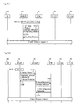
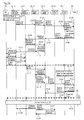
- FIG. 10 it is assumed that the information of the origination address of Source eNode B 10-S and the origination addresses of neighboring eNode B 10 have already been saved in memory unit 34A of S-GW 30 by means of any of the above-described Examples 1-4 of the operation of transmitting the origination address of eNode B 10.
- uplink packet data are received in S-GW 30 from Target eNode B 10-T in Step 2307 through the same processes as in FIG. 2 .
- control unit 33A of S-GW 30 is able to verify the safety of the received packet data without waiting for subsequent messages (Path Switch Request message and User Plane Update Request message) from Target eNode B 10-T by way of MME 20.
- control unit 33A of S-GW 30 collates the origination address of received packet data with origination addresses that are saved in memory unit 34A in Step 701. In this case, an origination address that matches the origination address of the packet data that were received is present in memory unit 34A, whereby control unit 33A judges that the received packet data are safe. In this case, transmission unit 32A transfers the received packet data to P-GW 40 in Step 702.
- transmission unit 11A of Target eNode B 10-T transmits to MME 20 a Path Switch Request message that contains information of the origination addresses of neighboring eNode B 10 in Step 703, and transmission unit 22A of MME 20 transmits to S-GW 30 a User Plane Update Request message that contains information of the origination addresses of neighboring eNode B 10 of Target eNode B 10-T in Step 704.
- S-GW 30 the information of the origination addresses of neighboring eNode B 10 of Target eNode B 10-T is saved in memory unit 34A by control unit 33A.
- S-GW 30 is able to use the information of the origination addresses of neighboring eNode B 10 of Source eNode B 10-S to verify the safety of packet data received from eNode B 10 despite the occurrence of a handover.
- FIG. 11 and FIG. 12 parts that are identical to FIG. 2 and parts common to FIG. 11 and FIG. 12 are given the same reference numbers.
- FIG. 11 and FIG. 12 it is assumed that information of the origination address of Source eNode B 10-S and the origination addresses of neighboring eNode B 10 is saved in memory unit 34A of S-GW 30 by means of any of Examples 1-4 of the operation of transmitting the origination address of eNode B 10 described hereinabove.
- uplink packet data are received in S-GW 30 from Target eNode B 10-T in Step 2307 through the same processes as FIG. 2 .
- control unit 33A of S-GW 30 next collates the origination address of the received packet data with origination addresses that are saved in memory unit 34A. In this case, it is assumed that an origination address that matches the origination address of the received packet data is not present in memory unit 34A, and control unit 33A therefore judges that the received packet data are dangerous.
- control unit 33A of S-GW 30 begins storing the received packet data in a buffer (not shown in the figure) in Step 802, and starts time measurement by means of a timer (not shown) in Step 803.
- transmission unit 11A of Target eNode B 10-T Upon transmission of a Handover Complete message from UE 60 in Step 2308, transmission unit 11A of Target eNode B 10-T transmits to MME 20 a Path Switch Request message that contains information of the origination address of its own eNode B 10 in Step 804. Transmission unit 22A of MME 20 next transmits to S-GW 30 a User Plane Update Request message that contains information of the origination address of eNode B 10 of Target eNode B 10-T in Step 805.
- control unit 33A of S-GW 30 stops the timer and discards the received packet data from the buffer in Step 902.
- control unit 33A of S-GW 30 discards the received packet data without storing it in the buffer in Step 904 and terminates the transfer to P-GW 40 in Step 905.
- S-GW 30 is able to use information of the origination addresses of neighboring eNode B 10 of Source eNode B 10-S and information of the origination address of Target eNode B 10-T itself to verify the safety of packet data received from eNode B 10.
- Target eNode B 10-T individually reports origination addresses and the origination address therefore does not necessarily need to be made identical to the termination address, whereby the degree of freedom of design of the radio communication system can be raised. The reason for this effect is explained hereinbelow.
- S-GW 30 collates the origination address of packet data received from eNode B 10 with the termination address of eNode B 10 that was reported from MME 20 at the time of setting a bearer, and if the addresses do not match, is able to judge the received packet data as dangerous and discard the data.
- a configuration that does not require that the origination address and termination address of eNode B 10 be made identical as in the present example is not only able to raise the degree of freedom in design of the radio communication system but can also further increase the security of the radio communication system.
- the termination address and origination address of eNode B 10 are also made identical in the design of a radio communication system. In this case, when MME 20 receives only one address from Target eNode B 10-T in Step 804, MME 20 is unable to judge whether this address is the origination address or not.
- Target eNode B 10-T is able to include information (Indicator) indicating that the origination address and termination address are equal by adding to a Path Switch Request message.
- MME 20 is able to judge whether the address received from Target eNode B 10-T is an origination address or not in Step 804, whereby the safety of packet data received from eNode B 10 can be verified.
- FIG. 13 and FIG. 14 parts that are identical to FIG. 2 and parts that are common to FIG. 13 and FIG. 14 are given the same reference numbers.
- uplink packet data are received in S-GW 30 from Target eNode B 10-T in Step 2307 through the same processes as FIG. 2 .
- control unit 33A of S-GW 30 next collates the origination address of the received packet data with origination addresses saved in memory unit 34A. In this case, it is assumed that an origination address that matches the origination address of the received packet data is not present in memory unit 34A, and control unit 33A therefore judges that the received packet data are dangerous.
- control unit 33A of S-GW 30 starts time measurement by means of a timer (not shown) in Step 1002, and transmission unit 32A continues to transfer the received packet data to P-GW 40 in Step 1003.
- transmission unit 11A of Target eNode B 10-T transmits to MME 20 a Path Switch Request message that contains information of the origination address of its own eNode B 10 in Step 1004.
- Transmission unit 22A of MME 20 next transmits to S-GW 30 a User Plane Update Request message that contains information of the origination address of eNode B 10 of Target eNode B 10-T in Step 1005.
- control unit 33A of S-GW 30 in Step 1006 next collates the origination address of packet data that were received in Step 2307 with the origination address of Target eNode B 10-T that was received in Step 1005. In this case, the origination address of the received packet data matches the origination address of Target eNode B 10-T, and control unit 33A therefore judges that the received packet data are safe and halts the timer in Step 1007.
- control unit 33A of S-GW 30 stops the timer in Step 1102.
- control unit 33A of S-GW 30 discards the received packet data in Step 1104 and halts the transfer to P-GW 40 in Step 1105.
- S-GW 30 is able to use the information of the origination address of neighboring eNode B 10 of Source eNode B 10-S and the information of the origination address of Target eNode B 10-T itself to verify the safety of packet data that are received from eNode B 10.
- the origination address and termination address of eNode B 10 need not be made identical, whereby both the degree of freedom of design of the radio communication system can be raised and the security of the radio communication system can be augmented.
- Target eNode B 10-T is able to include information indicating that the origination address and termination address are identical by adding to a Path Switch Request message in Step 1104.
- eNode B 10 includes transmission unit 11B that directly transmits to S-GW 30 packet data that contain in a header information of the origination addresses of neighboring eNode B 10.
- the information of the origination addresses of neighboring eNode B 10 can conceivably be set in eNode B 10 by the manual operation of an operator in advance, but the present exemplary embodiment is not limited to this form.
- S-GW 30 includes reception unit 31 B that receives from eNode B 10 packet data that include in a header information of the origination address of neighboring eNode B 10.
- eNode B 10 includes reception unit 12A and control unit 13A in addition to the above-described transmission unit 11A.
- Transmission unit 11 B is a component that carries out processes of transmitting messages and packet data to S-GW 30, an example being a process of transmitting to S-GW 30 packet data that contain in a header information of the origination addresses of neighboring eNode B 10 as described hereinabove.
- Reception unit 12B carries out processes of receiving messages and packet data from S-GW 30.
- Control unit 13B carries out processes such as generating messages that contain information that is to be transmitted to S-GW 30 and packet data that contain this information in a header.
- transmission and reception of messages and packet data by transmission unit 11 B, reception unit 12B, and control unit 13B are assumed to be carried out with UE 60, other eNode B 10, and MME 20.
- S-GW 30 includes transmission unit 32B, control unit 33B and memory unit 34B in addition to the above-described reception unit 31B.
- Reception unit 31 B is a component that carries out processes of receiving messages and packet data from eNode B 10, an example being the process of receiving from eNode B 10 packet data that contain in a header information of the origination addresses of neighboring eNode B 10 as described hereinabove.
- Transmission unit 32B carries out processes of transmitting messages and packet data to eNode B 10.
- Control unit 33B carries out processes such as a process of generating messages that contain information that is to be transmitted to eNode B 10, a process of saving in memory unit 34B information of the origination addresses of neighboring eNode B 10, and a process of collating the origination address of packet data that are received from eNode B 10 with origination addresses that are saved in memory unit 34B to verify the safety of received packet data.
- transmission and reception of messages and packet data by means of transmission unit 32B, reception unit 31B, and control unit 33B are assumed to be carried out with MME 20 and P-GW 40.
- a handover operation of the present exemplary embodiment is next described with reference to FIG. 17 .
- FIG. 17 Because approximately the same handover operation is carried out in FIG. 17 as in FIG. 2 , only characteristic parts of the present exemplary embodiment are shown and other parts are omitted.
- UE 60 moves from the area of Source eNode B 10-S to the area of Target eNode B 10-T, whereby control unit 13B of Source eNode B 10-S has determined a handover in Step 2301.
- control unit 13B of Source eNode B 10-S thereupon includes the origination addresses of neighboring eNode B 10 in the header of the packet data that were received from UE 60 and transmission unit 11B transmits the packet data to S-GW 30.
- GTP GPRS Tunneling Protocol, where GPRS is General Packet Radio Service
- GPRS General Packet Radio Service
- control unit 13B of Source eNode B 10-S includes the origination addresses of neighboring eNode B 10 in the GTP header as shown in FIG. 18 (3GPP TS 29.060, V8.2.0 - 6)
- a portion noting the Type of Extension Header is included in the GTP header as shown in the upper table of FIG. 18 .
- origination addresses of neighboring eNode B 10 that are defined as shown in the central table of FIG. 18 are noted in this portion.
- the notation content at this time is as shown in the lower table of FIG. 18 .
- S-GW 30 information of the origination addresses of neighboring eNode B 10 of Source eNode B 10-S is saved in memory unit 34B by control unit 33B.
- S-GW 30 is able to acquire from Source eNode B 10-S, at the time of deciding handover, the origination addresses of neighboring eNode B 10 that have a potential of becoming Target eNode B 10-T.
- the information of the origination addresses of Source eNode B 10-S can be acquired from Source eNode B 10-S at the time of an attach.
- S-GW 30 is able to verify the safety of packet data that have been received from eNode B 10 even in the event of a handover and is thus able to ensure the security of the radio communication system.
- information of the origination address of eNode B 10 is transmitted to S-GW 30 from eNode B 10 by way of MME 20 or directly from eNode B 10, whereby manual operation by an operator can be reduced.
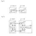
- eNode B 10 includes transmission unit 11C that transmits to MME 20 a message containing information of the origination address of Target eNode B 10-T when UE 60 performs handover that takes its own eNode B 10 as Source eNode B 10-S.
- the information of Target eNode B 10-T is received from Target eNode B 10-T, as will be described hereinbelow.
- MME 20 includes reception unit 21C that receives messages containing information of the origination address of Target eNode B 10-T from eNode B 10 and transmission unit 22C that transmits to S-GW 30 messages containing information of the origination address of Target eNode B 10-T.
- S-GW 30 includes reception unit 31C that receives from MME 20 messages containing information of the origination address of Target eNode B 10-T.
- eNode B 10 includes reception unit 12C and control unit 13C in addition to the above-described transmission unit 11C.
- Transmission unit 11C is a component that carries out the processes of transmitting messages and packet data to MME 20, one example being a process of transmitting to MME 20 a message containing information of the origination address of Target eNode B 10-T as described hereinabove.
- Reception unit 12C carries out processes of receiving messages and packet data from MME 20.
- Control unit 13C carries out processes such as generating messages that contain information that is to be transmitted to MME 20.
- transmission and reception of messages and packet data by means of transmission unit 11C, reception unit 12C, and control unit 13C are assumed to be carried out with UE 60, other eNode B 10, and S-GW 30.
- MME 20 includes control unit 23C in addition to the above-described reception unit 21C and transmission unit 22C.
- Reception unit 21C is a component that carries out processes of receiving messages and packet data from eNode B 10 and S-GW 30, one example being the process of receiving messages that contain information of the origination address of Target eNode B 10-T from eNode B 10, as described hereinabove.
- Transmission unit 22C is a component that carries out processes of transmitting messages and packet data to eNode B 10 and S-GW 30, one example being the process of transmitting to S-GW 30 messages that contain information of the origination address of Target eNode B 10-T, as described hereinabove.
- Control unit 23C carries out processes such as generating messages that contain information that is to be transmitted to eNode B 10 and S-GW 30.
- S-GW 30 includes transmission unit 32C, control unit 33C, and memory unit 34C, in addition to the above-described reception unit 31C.
- Reception unit 31C is a component that carries out processes of receiving messages and packet data from MME 20, one example being a process of receiving messages that contain information of the origination address of Target eNode B 10-T from MME 20, as described hereinabove.
- Transmission unit 32C carries out processes of transmitting messages and packet data to MME 20.
- Control unit 33C carries out a process of generating messages that contain information that is to be transmitted to MME 20, a process of saving in memory unit 34C the information of the origination addresses of neighboring eNode B 10, and a process verifying the safety of received packet data by collating the origination address of packet data received from MME 20 with origination addresses saved in memory unit 34C.
- the handover operation of the present exemplary embodiment is next described with reference to FIG. 21 .
- FIG. 21 parts identical to FIG. 2 are given the same reference numbers.
- FIG. 21 it is here assumed that the origination address of Source eNode B 10-S has already been reported to S-GW 30 and already saved in memory unit 34C of S-GW 30 by any of Examples 1-4 of the operation of transmitting the origination address of eNode B 10 in the above-described first exemplary embodiment.
- transmission unit 11C of Target eNode B 10-T in Step 1801 transmits to Source eNode B 10-S a response message (Handover Response message) to the Handover Request message, in which the response message contains information of the origination address of its own Target eNode B 10-T.
- Step 1802 transmission unit 11C of Source eNode B 10-S transmits to MME 20 a message (Handover Inform message) indicating that handover has occurred and including information of the origination address of Target eNode B 10-T.
- transmission unit 22C of MME 20 transmits to S-GW 30 a message (Pre-User Plane Update Request message) that contains information of the origination address of Target eNode B 10-T.
- transmission unit 32C of S-GW 30 next transmits to MME 20 a response message (Pre-User Plane Update Response message) to the Pre-User Plane Update Request message.
- S-GW 30 information of the origination address of Target eNode B 10-T is saved in memory unit 34C by means of control unit 33C.
- control unit 33C of S-GW 30 is able to verify the safety of received packet data without waiting for a subsequent messages (Path Switch Request message and User Plane Update Request message) from Target eNode B 10-T by way of MME 20.
- control unit 33C of S-GW 30 in Step 1805 collates the origination address of received packet data with the origination addresses saved in memory unit 34C.
- an origination address that matches the origination address of the received packet data is present in memory unit 34C, whereby control unit 33C judges that the received packet data are safe.
- transmission unit 32C transfers the received packet data to P-GW 40 in Step 1806.
- the same processes as FIG. 2 are subsequently carried out.
- the information of the origination address of Source eNode B 10-S can also be acquired from Source eNode B 10-S at the time of an attach by means of any of Examples 1-4 of the operation of transmitting the origination address of eNode B 10 in the above-described first exemplary embodiment.
- S-GW 30 is able to acquire the origination address of Target eNode B 10-T from Source eNode B 10-S at the time of a decision of handover.
- S-GW 30 is able to verify the safety of packet data received from eNode B 10 despite the occurrence of handover, and is able to ensure the security of the radio communication system.
- Source eNode B 10-S transmits information of the origination address of Target eNode B 10-T to S-GW 30 by way of MME 20, whereby S-GW 30 is able to verify the safety from the initial packet data that are received from Target eNode B 10-T.
- the information of the origination address of eNode B 10 is transmitted from eNode B 10 to S-GW 30, and manual operation by an operator can therefore be reduced.
- Source eNode B 10-S transmits information of the origination address of Target eNode B 10-T rather than the origination addresses of neighboring eNode B 10, whereby the amount of information that is transmitted can be reduced compared to a case of transmitting information of the origination addresses of neighboring eNode B 10.
- S-GW 30 includes transmission unit 32D that, in a state in which UE 60 is roaming in an outside network and carries out handover that accompanies a change to its own S-GW 30, transmits a message containing information of the origination address of its own S-GW 30 to P-GW 40 by way of a public network.
- P-GW 40 according to the present exemplary embodiment includes reception unit 41D that receives, from Target S-GW30-T that follows the change by handover, information of the origination address of Target eNode B 10-T by way of a public network.
- S-GW 30 includes reception unit 31D and control unit 3 3D, in addition to the above-described transmission unit 32D.
- Transmission unit 32D is a component that carries out processes of transmitting messages and packet data to P-GW 40, one example being the process of transmitting to P-GW a message containing information of the origination address of its own S-GW 30 as described hereinabove.
- Reception unit 31D carries out processes of receiving messages and packet data from P-GW 40.
- Control unit 33D carries out processes such as generating messages containing information that is to be transmitted to P-GW 40.
- P-GW 40 includes transmission unit 42D, control unit 43D, and memory unit 44D, in addition to the above-described reception unit 41D.
- Reception unit 41D is a component that carries out processes of receiving messages and packet data from S-GW 30, one example being a process of receiving messages that contain information of the origination address of Target S-GW 30-T from Target S-GW 30-T as described hereinabove.
- Transmission unit 42D carries out processes of transmitting messages and packet data to S-GW 30.
- Control unit 43D carries out a process of generating messages containing information that is to be transmitted to S-GW 30, a process of saving in memory unit 34D information of the origination address of Target S-GW 30-T, and a process of verifying the safety of received packet data by collating the origination address of packet data received from Target S-GW 30-T with origination addresses saved in memory unit 34D.
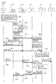
- Step 2101 it is assumed that Source eNode B 10-S has determined in Step 2101 a handover that accompanies change from Source S-GW 30-S to Target S-GW 30-T due to movement of UE 60 that is roaming in an outside network from the area of Source eNode B 10-S to the area of Target eNode B 10-T.
- Step 2102 Source eNode B 10-S thereupon transmits to Source MME 20 a message (Handover Required message) to prepare for the handover, and Source MME 20 in Step 2103 transmits to Target MME 20-T a message (Forward Relocation Request message) to send the Context of UE 60 and the address of P-GW 40.
- Target MME 20-T next transmits to Target S-GW 30-T a message (Create Bearer Request message) to request creation of a bearer
- Target S-GW 30-T in Step 2105 transmits to P-GW 40 a message (Pre-Update Bearer Request message) containing information of the origination address of Target S-GW 30-T.
- P-GW 40 the information of the origination address of Target S-GW 30-T is saved in memory unit 44D by control unit 43D.
- Step 2106 transmission unit 42D of P-GW 40 transmits to Target S-GW 30-T a response message (Pre-Update Bearer Response message) to the Pre-Update Bearer Request message, and transmission unit 32D of Target S-GW 30-T transmits to Target MME 20-T a response message (Create Bearer Response message) to the Create Bearer Request message in Step 2107.
- Target MME 20-T next transmits to Target eNode B 10-T a message (Handover Request message) requesting handover, and Target eNode B 10-T transmits to Target MME 20-T a response message (Handover Request Acknowledgement message) to the handover request in Step 2109.
- Target MME 20-T next transmits to Source MME 20-S a response message (Forward Relocation Response message) to the Forward Relocation Request message, and Source MME 20-S transmits to UE 60 by way of Source eNode B 10-S a message (Handover Command message) commanding handover in Steps 2111 and 2112.
- a response message Forward Relocation Response message
- Source MME 20-S transmits to UE 60 by way of Source eNode B 10-S a message (Handover Command message) commanding handover in Steps 2111 and 2112.
- UE 60 After radio synchronization has been established between UE 60 and Target eNode B 10-T in Step 2113, UE 60 transmits to Target eNode B 10-T a message (Handover Complete message) indicating completion of handover in Step 2114.
- a message (Handover Complete message) indicating completion of handover in Step 2114.
- control unit 43D of P-GW 40 collates the origination address of the received packet data with the origination addresses saved in memory unit 44D in Step 2116.
- an origination address of Target S-GW 30-T that matches the origination address of the received packet data is present in memory unit 44D, and control unit 43D therefore judges that the received packet data are safe.
- transmission unit 42D transfers the received packet data within its own network.
- Target eNode B 10-T next transmits to Target MME 20-T a message (Handover Notify message) reporting that UE 60 is connected to Target eNode B 10-T, in Step 2118 Target MME 20-T transmits to Source MME 20-S a message (Forward Relocation Complete message) reporting that UE 60 has performed handover, and in Step 2119 Source MME 20-S transmits to Target MME 20-T a response message (Forward Relocation Complete Acknowledgement message) to the Forward Relocation Complete message.
- a message Haandover Notify message
- Source MME 20-S transmits to Target MME 20-S a message (Forward Relocation Complete message) reporting that UE 60 has performed handover
- Source MME 20-S transmits to Target MME 20-T a response message (Forward Relocation Complete Acknowledgement message) to the Forward Relocation Complete message.
- Target MME 20-T next transmits to P-GW 40 by way of Target S-GW 30-T a message (Update Bearer Request message) requesting updating of the bearer, and in Steps 2122 and 2123, transmission unit 42D of P-GW 40 transmits a response message (Update Bearer Response message) to the Update Bearer Request message to Target MME 20-T by way of Target S-GW 30-T. Transmission unit 42D of P-GW 40 then transmits to Target S-GW 30-T downlink packet data in Step 2124.
- a message Update Bearer Request message
- Transmission unit 42D of P-GW 40 transmits to Target S-GW 30-T downlink packet data in Step 2124.
- Source MME 20-S in Step 2126 transmits to Source eNode B 10-S a message (Release Resource message) indicating the release of resources.
- Source MME 20-S further transmits to Source S-GW 30-S a message (Delete Bearer Request message) requesting the deletion of the bearer, and transmission unit 32D of Source S-GW 30-S transmits to Source MME 20-S a response message (Delete Bearer Response message) to the Delete Bearer Request message in Step 2128.
- FIG. 24 of the present exemplary embodiment are not limited to a case in which UE 60 is roaming in an outside network.
- P-GW 40 when a handover is performed that accompanies change from Source S-GW 30-S to Target S-GW 30-T, P-GW 40 is able to acquire information of the origination address of Target S-GW 30-T.
- P-GW 40 is able to verify the safety of packet data that are received from S-GW 30 despite the occurrence of handover that accompanies change of S-GW 30, and is therefore able to ensure the security of the radio communication system.
- P-GW 40 receives packet data from S-GW 30 by way of a public network, and the possibility of threat to the security of radio communication system is therefore high.
- verification of the safety of packet data by means of the present exemplary embodiment is even more effective.
- Source S-GW 30-S transmits information of the origination address of Target S-GW 30-T to P-GW 40 by way of MME 20 before UE 60 begins transmission of uplink data (packet data) by way of Target eNode B 10-T (for example, before a Handover Command message to UE 60), whereby P-GW 40 is able to verify the safety from the initial packet data that are received from Target S-GW 30-T.
- an LTE radio communication system has been described by way of example in the foregoing exemplary embodiments, but the present invention is not limited to an LTE radio communication system and can be applied to other radio communication systems equipped with a base station, a mobile management node, and a gateway.
- a radio communication system in which a mobile management node and a gateway are separated was described by way of example, but the present invention can also be applied to a radio communication system in which a mobile management node and gateway are unified.
Landscapes
- Engineering & Computer Science (AREA)
- Computer Security & Cryptography (AREA)
- Computer Networks & Wireless Communication (AREA)
- Signal Processing (AREA)
- Computer Hardware Design (AREA)
- Computing Systems (AREA)
- General Engineering & Computer Science (AREA)
- Mobile Radio Communication Systems (AREA)
Applications Claiming Priority (2)
| Application Number | Priority Date | Filing Date | Title |
|---|---|---|---|
| JP2008021303 | 2008-01-31 | ||
| PCT/JP2008/073352 WO2009096121A1 (fr) | 2008-01-31 | 2008-12-22 | Système et procédé de radiocommunications, dispositif station de base, et dispositif passerelle |
Publications (2)
| Publication Number | Publication Date |
|---|---|
| EP2237587A1 true EP2237587A1 (fr) | 2010-10-06 |
| EP2237587A4 EP2237587A4 (fr) | 2017-03-22 |
Family
ID=40912479
Family Applications (1)
| Application Number | Title | Priority Date | Filing Date |
|---|---|---|---|
| EP08871880.4A Withdrawn EP2237587A4 (fr) | 2008-01-31 | 2008-12-22 | Système et procédé de radiocommunications, dispositif station de base, et dispositif passerelle |
Country Status (5)
| Country | Link |
|---|---|
| US (1) | US9271195B2 (fr) |
| EP (1) | EP2237587A4 (fr) |
| JP (1) | JP5163658B2 (fr) |
| CN (1) | CN101933350B (fr) |
| WO (1) | WO2009096121A1 (fr) |
Cited By (3)
| Publication number | Priority date | Publication date | Assignee | Title |
|---|---|---|---|---|
| US9642045B2 (en) | 2011-01-10 | 2017-05-02 | Huawei Technologies Co., Ltd. | Method and device for releasing context-related resource of user equipment |
| WO2019125239A1 (fr) * | 2017-12-19 | 2019-06-27 | Telefonaktiebolaget Lm Ericsson (Publ) | Procédé et nœud de gestion dans un réseau de communication, de prise en charge de gestion de nœuds de réseau sur la base de messages de lldp |
| US11552994B2 (en) | 2017-12-19 | 2023-01-10 | Telefonaktiebolaget Lm Ericsson (Publ) | Methods and nodes for handling LLDP messages in a communication network |
Families Citing this family (12)
| Publication number | Priority date | Publication date | Assignee | Title |
|---|---|---|---|---|
| CN100584093C (zh) | 2006-08-15 | 2010-01-20 | 华为技术有限公司 | 一种在移动通信系统中转移用户设备的方法及系统 |
| WO2010078676A1 (fr) * | 2008-12-30 | 2010-07-15 | 中兴通讯股份有限公司 | Procédé pour obtenir l'adresse de transmission de la station de base cible et procédé pour établir la connexion d'interface x2 |
| CN102026130B (zh) * | 2009-09-18 | 2014-04-09 | 中兴通讯股份有限公司 | 一种紧急区域标识的通知方法、系统和装置 |
| CN102905329A (zh) * | 2011-07-29 | 2013-01-30 | 北京三星通信技术研究有限公司 | 一种支持切换的方法 |
| CN102355402B (zh) * | 2011-08-03 | 2014-05-07 | 华为技术有限公司 | 一种基于vpn路由建立lsp的方法、系统和路由器 |
| CN103002521B (zh) * | 2011-09-08 | 2015-06-03 | 华为技术有限公司 | 传递上下文的方法及移动性管理实体 |
| CN104221435A (zh) * | 2011-12-12 | 2014-12-17 | 欧普提斯无线技术有限责任公司 | 切换限制 |
| US9167493B2 (en) | 2012-06-15 | 2015-10-20 | At&T Intellectual Property I, L.P. | Method and apparatus for providing a cloud-based mobility in a wireless network |
| US20150215056A1 (en) * | 2012-08-17 | 2015-07-30 | Nec Corporation | Mobile communication system, mobile communication method, gateway apparatus, and radio base station |
| RU2669582C2 (ru) * | 2014-05-30 | 2018-10-12 | Хуавэй Текнолоджиз Ко., Лтд. | Способ и устройство смены пути услуги |
| US20180199241A1 (en) * | 2015-07-03 | 2018-07-12 | Lg Electronics Inc. | Method and apparatus for enhancing coordination of lte-wlan in wireless communication system |
| WO2018000310A1 (fr) * | 2016-06-30 | 2018-01-04 | 华为技术有限公司 | Procédé de détermination de trajet de données, et dispositif de commande |
Family Cites Families (17)
| Publication number | Priority date | Publication date | Assignee | Title |
|---|---|---|---|---|
| JPH0630152A (ja) | 1992-07-08 | 1994-02-04 | Nippon Telegr & Teleph Corp <Ntt> | 構内通信システム |
| JP3006504B2 (ja) * | 1996-08-27 | 2000-02-07 | 日本電気株式会社 | 無線ネットワークにおける無線端末の認証方法および無線ネットワーク |
| JP3758808B2 (ja) | 1997-05-15 | 2006-03-22 | ソニー株式会社 | 通信端末および通信方法 |
| JP3880419B2 (ja) * | 2002-02-21 | 2007-02-14 | 日本電信電話株式会社 | 無線アクセスネットワーク、無線マルチホップネットワーク、認証サーバ、基地局及び無線端末 |
| JP3812455B2 (ja) * | 2002-02-15 | 2006-08-23 | 日本電信電話株式会社 | ゲートウェイ装置およびその位置登録方法、認証方法、位置管理方法、ならびにそのプログラムと記録媒体 |
| ATE377336T1 (de) * | 2002-08-05 | 2007-11-15 | Roamware Inc | Verfahren und system zur weiterleitung von verkehr in einem zellularen netzwerk |
| JP3813603B2 (ja) * | 2002-09-12 | 2006-08-23 | 財団法人流通システム開発センタ− | Ip網を用いた端末間通信接続制御方法 |
| JP4254196B2 (ja) | 2002-10-17 | 2009-04-15 | ソニー株式会社 | 通信端末装置、通信基地局装置、通信中継装置、および方法、並びにコンピュータ・プログラム |
| JP2004221752A (ja) | 2003-01-10 | 2004-08-05 | Funai Electric Co Ltd | 無線通信ネットワークシステムおよびデータ伝送方法 |
| JP4281533B2 (ja) * | 2003-11-27 | 2009-06-17 | 日本電気株式会社 | 無線通信システムおよび基地局セキュリティ方法 |
| WO2007083541A1 (fr) * | 2006-01-18 | 2007-07-26 | Nec Corporation | Système de communication et méthode de gestion des informations |
| JP4097682B2 (ja) | 2006-06-16 | 2008-06-11 | ヤフー株式会社 | ペイパービジット広告システム |
| US9118529B2 (en) * | 2006-06-20 | 2015-08-25 | Qualcomm Incorporated | Discovery of neighbor cells |
| JP4869870B2 (ja) * | 2006-10-31 | 2012-02-08 | 株式会社エヌ・ティ・ティ・ドコモ | アクセスゲートウェイ装置及びトラッキング・エリア識別子通知方法 |
| JP4703577B2 (ja) * | 2007-01-17 | 2011-06-15 | 株式会社エヌ・ティ・ティ・ドコモ | 論理インタフェース設定方法、無線基地局、通信管理装置 |
| US20080311911A1 (en) * | 2007-06-15 | 2008-12-18 | Nokia Siemens Networks Oy | Handover trigger for an inter-access-gateway interface |
| JP5018892B2 (ja) * | 2007-11-19 | 2012-09-05 | 富士通株式会社 | 通信システム |
-
2008
- 2008-12-22 JP JP2009551409A patent/JP5163658B2/ja not_active Expired - Fee Related
- 2008-12-22 US US12/810,093 patent/US9271195B2/en active Active
- 2008-12-22 EP EP08871880.4A patent/EP2237587A4/fr not_active Withdrawn
- 2008-12-22 WO PCT/JP2008/073352 patent/WO2009096121A1/fr not_active Ceased
- 2008-12-22 CN CN200880125990.4A patent/CN101933350B/zh not_active Expired - Fee Related
Non-Patent Citations (1)
| Title |
|---|
| See references of WO2009096121A1 * |
Cited By (4)
| Publication number | Priority date | Publication date | Assignee | Title |
|---|---|---|---|---|
| US9642045B2 (en) | 2011-01-10 | 2017-05-02 | Huawei Technologies Co., Ltd. | Method and device for releasing context-related resource of user equipment |
| WO2019125239A1 (fr) * | 2017-12-19 | 2019-06-27 | Telefonaktiebolaget Lm Ericsson (Publ) | Procédé et nœud de gestion dans un réseau de communication, de prise en charge de gestion de nœuds de réseau sur la base de messages de lldp |
| US11431728B2 (en) | 2017-12-19 | 2022-08-30 | Telefonaktiebolaget Lm Ericsson (Publ) | Method and management node in a communication network, for supporting management of network nodes based on LLDP messages |
| US11552994B2 (en) | 2017-12-19 | 2023-01-10 | Telefonaktiebolaget Lm Ericsson (Publ) | Methods and nodes for handling LLDP messages in a communication network |
Also Published As
| Publication number | Publication date |
|---|---|
| US9271195B2 (en) | 2016-02-23 |
| US20100329208A1 (en) | 2010-12-30 |
| CN101933350A (zh) | 2010-12-29 |
| JP5163658B2 (ja) | 2013-03-13 |
| EP2237587A4 (fr) | 2017-03-22 |
| CN101933350B (zh) | 2016-01-20 |
| WO2009096121A1 (fr) | 2009-08-06 |
| JPWO2009096121A1 (ja) | 2011-05-26 |
Similar Documents
| Publication | Publication Date | Title |
|---|---|---|
| EP2237587A1 (fr) | Système et procédé de radiocommunications, dispositif station de base, et dispositif passerelle | |
| EP3576457B1 (fr) | Procédé de communication, dispositif de réseau d'accès et dispositif de réseau central | |
| US9661498B2 (en) | System and method for selection of security algorithms | |
| US8867484B2 (en) | Method, apparatus and computer program product for handover failure recovery | |
| KR101712865B1 (ko) | 이동 통신 시스템에서 비계층 프로토콜을 이용한 통신 지원 방법 및 장치 | |
| EP4033806A1 (fr) | Procédé de transmission de données, dispositif de communication, et système de communication | |
| CN111601315B (zh) | 一种支持对家用基站进行验证的方法 | |
| WO2013093723A2 (fr) | Systèmes et procédés de communication sans fil | |
| US8543089B2 (en) | Method for performing an authentication of entities during establishment of wireless call connection | |
| WO2007078159A1 (fr) | Procede et appareil pour emettre des donnees sip d'equipement utilisateur en mode repos dans un systeme de communications mobiles | |
| US20110060837A1 (en) | Method, system and device for connection establishment based on lte/sae system | |
| WO2011158377A1 (fr) | Procédé de communication sans fil, appareil de communication sans fil et système de communication sans fil | |
| KR102393322B1 (ko) | 5g 코어망에서 네트워크 슬라이스 식별자를 결정하여 전달하는 방법 | |
| CN113904781B (zh) | 切片认证方法及系统 | |
| US8606228B2 (en) | Method, user network equipment and management system thereof for secure data transmission | |
| KR102296080B1 (ko) | 5g sa 코어망 장애 발생 시의 서비스 복구 방법 | |
| US9247483B2 (en) | Method and system for data traffic offload | |
| US7957281B2 (en) | Method for interworking between access control router and position determination entity in position recognition system based on portable internet and system therefor | |
| CN114270881B (zh) | 一种接入网络方法和装置 | |
| KR101434750B1 (ko) | 이동통신망에서 지리 정보를 이용한 무선랜 선인증 방법 및 장치 | |
| CN100450299C (zh) | 一种基于预配置处理的连接建立方法、装置及系统 | |
| EP4683369A1 (fr) | Procédé, appareil et système de communication | |
| CN113938349B (zh) | 无线工业总线通信方法及系统 | |
| WO2010026452A2 (fr) | Communication entre stations de base à l'aide d'un dispositif terminal |
Legal Events
| Date | Code | Title | Description |
|---|---|---|---|
| PUAI | Public reference made under article 153(3) epc to a published international application that has entered the european phase |
Free format text: ORIGINAL CODE: 0009012 |
|
| 17P | Request for examination filed |
Effective date: 20100802 |
|
| AK | Designated contracting states |
Kind code of ref document: A1 Designated state(s): AT BE BG CH CY CZ DE DK EE ES FI FR GB GR HR HU IE IS IT LI LT LU LV MC MT NL NO PL PT RO SE SI SK TR |
|
| AX | Request for extension of the european patent |
Extension state: AL BA MK RS |
|
| DAX | Request for extension of the european patent (deleted) | ||
| RA4 | Supplementary search report drawn up and despatched (corrected) |
Effective date: 20170217 |
|
| RIC1 | Information provided on ipc code assigned before grant |
Ipc: H04W 88/08 20090101ALN20170213BHEP Ipc: H04W 12/10 20090101AFI20170213BHEP Ipc: H04L 29/06 20060101ALI20170213BHEP Ipc: H04L 12/66 20060101ALI20170213BHEP Ipc: H04W 36/10 20090101ALI20170213BHEP Ipc: H04W 36/00 20090101ALI20170213BHEP |
|
| STAA | Information on the status of an ep patent application or granted ep patent |
Free format text: STATUS: THE APPLICATION HAS BEEN WITHDRAWN |
|
| 18W | Application withdrawn |
Effective date: 20181023 |