EP2237904B1 - Procede de fabrication d'elements transversaux pour courroie d'entraînement - Google Patents
Procede de fabrication d'elements transversaux pour courroie d'entraînement Download PDFInfo
- Publication number
- EP2237904B1 EP2237904B1 EP07851969A EP07851969A EP2237904B1 EP 2237904 B1 EP2237904 B1 EP 2237904B1 EP 07851969 A EP07851969 A EP 07851969A EP 07851969 A EP07851969 A EP 07851969A EP 2237904 B1 EP2237904 B1 EP 2237904B1
- Authority
- EP
- European Patent Office
- Prior art keywords
- strip
- transverse elements
- drive belt
- elements
- stage
- Prior art date
- Legal status (The legal status is an assumption and is not a legal conclusion. Google has not performed a legal analysis and makes no representation as to the accuracy of the status listed.)
- Not-in-force
Links
- 238000000034 method Methods 0.000 title claims abstract description 58
- 238000004519 manufacturing process Methods 0.000 title claims abstract description 34
- 239000000463 material Substances 0.000 claims abstract description 13
- 238000005520 cutting process Methods 0.000 claims abstract description 7
- 229910000831 Steel Inorganic materials 0.000 claims abstract description 4
- 239000010959 steel Substances 0.000 claims abstract description 4
- 238000005496 tempering Methods 0.000 claims description 17
- 238000010791 quenching Methods 0.000 claims description 8
- 230000000171 quenching effect Effects 0.000 claims description 8
- 238000010438 heat treatment Methods 0.000 claims description 6
- 229910052751 metal Inorganic materials 0.000 claims description 4
- 229910001566 austenite Inorganic materials 0.000 claims description 3
- 229910000734 martensite Inorganic materials 0.000 claims description 3
- 238000001816 cooling Methods 0.000 claims 1
- 230000005540 biological transmission Effects 0.000 description 10
- 230000002349 favourable effect Effects 0.000 description 3
- 230000006698 induction Effects 0.000 description 3
- 238000010924 continuous production Methods 0.000 description 2
- 239000002184 metal Substances 0.000 description 2
- 230000009466 transformation Effects 0.000 description 2
- 229910000975 Carbon steel Inorganic materials 0.000 description 1
- 229910001240 Maraging steel Inorganic materials 0.000 description 1
- 230000004913 activation Effects 0.000 description 1
- 238000005452 bending Methods 0.000 description 1
- 230000015572 biosynthetic process Effects 0.000 description 1
- 229910052799 carbon Inorganic materials 0.000 description 1
- 239000010962 carbon steel Substances 0.000 description 1
- 230000005672 electromagnetic field Effects 0.000 description 1
- 238000011010 flushing procedure Methods 0.000 description 1
- 239000007788 liquid Substances 0.000 description 1
- 238000010008 shearing Methods 0.000 description 1
- 229910000859 α-Fe Inorganic materials 0.000 description 1
Images
Classifications
-
- F—MECHANICAL ENGINEERING; LIGHTING; HEATING; WEAPONS; BLASTING
- F16—ENGINEERING ELEMENTS AND UNITS; GENERAL MEASURES FOR PRODUCING AND MAINTAINING EFFECTIVE FUNCTIONING OF MACHINES OR INSTALLATIONS; THERMAL INSULATION IN GENERAL
- F16G—BELTS, CABLES, OR ROPES, PREDOMINANTLY USED FOR DRIVING PURPOSES; CHAINS; FITTINGS PREDOMINANTLY USED THEREFOR
- F16G5/00—V-belts, i.e. belts of tapered cross-section
- F16G5/16—V-belts, i.e. belts of tapered cross-section consisting of several parts
Definitions
- the present invention relates to a method for manufacturing a transverse element components of a flexible drive belt.
- a drive belt is predominantly used as a means for power transmission between two adjustable pulleys of the well-known continuously variable transmission that is mainly applied in motor vehicles.
- the present type of drive belt is generally known and is, for example, described in the European patent publication EP-A-1 554 507 .
- the known drive belt is composed of a multitude relatively thin transverse metal elements slideably provided on two laminated endless tensile means of the belt that are each composed of a set of mutually nested flat and thin metal rings, alternatively denoted bands.
- the rings are normally made from a maraging steel that combines a/o the properties of great tensile strength and good resistance against tensile stress and bending fatigue.
- the transverse elements are normally made from a basic chrome-carbon steel such as 75Cr1.
- the manufacturing of the transverse elements at least includes the step of gradually unwinding of a spirally wound up strip of base material and advancing, i.e.
- the latter process step of hardening typically includes at least three stages.
- a phase transformation from the basic ferrite material structure into austenite is effected by heating the transverse elements to above the critical temperature for austenite phase formation and sufficiently long for completing such phase transformation, in a second or quenching stage the transverse elements are rapidly cooled to form martensite, and in a third or tempering stage the transverse elements are heated again, however to a temperature that is considerably lower than the above austenizing temperature, for reducing the brittleness of the transverse element material.
- the known manufacturing method is favorable in terms of the limited handling effort, the effectiveness, i.e. efficiency thereof is considered sub-optimal.
- This problem originates from the fact that the production rate attainable with a common blanking device exceeds that of even an optimized hardening process station by a considerable margin.
- the known blanking devices can easily operate at a rate of over 5 blanking strokes per second, whereto the strip needs to be advanced, i.e. fed, to the blanking device for over 5 times the width dimension of the transverse elements or typically for more than 200 mm each second.
- the tempering stage of the hardening process typically requires in the order of 1 hour to complete, which implies that a furnace for heating the strip in the tempering stage would have to have the entirely impractical length of about 0.5 km to treat the advancing strip, i.e. to keep up with the production rate of the blanking device.
- the blanking device can only perform, i.e. be operated, at a fraction of its maximum stroke rate.
- the present invention sets out to improve on the above known manufacturing method and to create a variant thereof that is both practically feasible and that favorably allows the blanking device to perform at a much higher stroke rate.
- the above object is realized in general with the manufacturing method of the following claim 1.
- the continuous strip of base material is sequentially cut into strip sections of limited length, e.g. between 0.5 and 2.5 meter.
- each strip section contains at least one transverse element, but preferably a larger number of 25 up to 150 individual transverse elements. Accordingly, the unhardened transverse elements need not be handled individually nor directly, since the frame part of the said strip sections is available thereto.
- the hardening process station can be easily and favorably arranged to keep up with the production rate of the blanking device.
- the said strip sections are preferably loaded into a carrier rack, which can hold a number of such strip sections, in advance of the tempering stage of the hardening process.
- the tempering furnace is designed to accommodate one or more of such carrier racks, such that a few or possibly only one tempering furnace is required to keep up with the production rate of the blanking device.
- the carrier rack is provided with clamping means for holding the said strip sections that engage only the said frame part thereof.
- the strip of base material in the austenizing stage is considered highly favorable to inductively heat the strip of base material in the austenizing stage, either as a whole, whereto the strip is continuously carried through an induction coil that creates a controlled high frequency electromagnetic field, or as cut into individually strip sections that are heated in parallel inside a number of such induction coils.
- the said subsequent quenching stage of the manufacturing method can be performed very effectively by flushing the induction coils containing the heated strip sections with a liquid or a gas after the austenizing stage has been completed. In this way, the hardening heat treatment of the transverse elements will be ultimately uniform and can be easily and accurately controlled.
- the process step of cutting the strip into sections of limited length according to the invention is respectively carried out either only after the said quenching stage has been completed, or in advance of the process step of hardening, i.e. immediately following the process step of blanking.
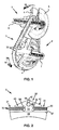
- Figure 1 shows the central parts of a known continuously variable transmission that is commonly applied in the drive-line of motor vehicles between the engine and the drive wheels thereof.
- the transmission comprises two pulleys 1, 2, each provided with two pulley discs 4, 5, between which a so-called pushbelt-type drive belt 3 is present for transmitting a rotational movement M and an accompanying torque from one pulley 1, 2 to the other 2, 1.
- the pulley discs 4, 5 are shaped generally conical and at least one pulley disc 4 is incorporated in the transmission axially moveable along a respective pulley shaft 6, 7 on which both discs 4, 5 are placed.
- the transmission normally also comprises activation means that impose on the said at least one movable disc 4 an axially oriented clamping force directed towards the respective other pulley disc 5 such that the drive belt 3 is clamped there between.
- a geometric transmission ratio of the transmission is determined by the quotient of an effective contact radius R2 of the drive belt 3 at the driven pulley 2 and an effective contact radius R1 of the drive belt 3 at the driving pulley 1, which may be varied continuously in range of values.
- the drive belt 3 comprises two laminated endless tensile means 31 and several hundred of relatively thin transverse elements 32 that are provided on the tensile means 31 movable along the longitudinal direction thereof and oriented predominantly transversely thereto.
- the transverse elements 32 take-up the said clamping force, such that at rotation of a driving pulley 1, friction between the discs 4, 5 and the drive belt 3, causes the elements 32 to be thrust in the said direction of movement M from the said driving pulley 1 to a driven pulley 2 and back again, thereby being guided and supported by the tensile means 31.
- Figure 2 provides a cross section of the known drive belt 3, which cross section is oriented in the longitudinal direction thereof.
- the transverse element 32 of the drive belt 3 is shown in a frontal view.
- the element 32 comprises three main parts, namely an essentially arrowhead-shaped top part 33, an essentially trapezoidal bottom part 35 and an essentially oblong pillar part 34 of relatively limited width that interconnects the said top and bottom parts 33, 35.
- the transverse elements 32 are incorporated in the drive belt 3 mounted on the endless tensile means 31 thereof that are each formed by a number of thin and flat metal rings 30 that are nested one around the other in the radial direction and that are each accommodated in a respective opening or recess 36 in the transverse element 32, each recess 36 provided on either side of the pillar part 34 between the element's top and bottom parts 33, 35.
- a longitudinally protruding stud 39 is provided on a front main face 40 of the transverse element 32, which stud 39 is to be accommodated in a hole 42 provided in a rear main face 41 of an adjacent transverse element 32.
- the stud 39 and hole 42 are provided to mutually align adjacent transverse elements 32 of the drive belt 3 transversely to its longitudinal direction during operation in the transmission.
- a so-called tilting edge 37 At the bottom part 35 of the transverse elements 32 below a so-called tilting edge 37 its thickness tapers-off at least effectively, so as to allow adjacent elements 32 to mutually tilt about the axially oriented tilting edge 37 when clamped between the discs 4, 5 of the pulleys 1, 2.
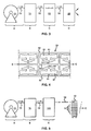
- FIG 4 a top view of the strip 50 is provided after the above process step of blanking B has been performed thereon.
- the strip 50 is composed of the frame part 52 and the transverse elements 32, which main parts 52, 32 of the strip 50 are still connected to each other through a connecting tab 51.
- a problem of this known manufacturing method is that the practically attainable production rates of the respective process steps A-D, in particular that of blanking B and hardening C, at least the tempering stage III thereof (but conventionally also the stages I and II of austinizing and quenching respectively) are entirely different.
- the slowest process step of hardening C determines the overall production rate of the entire process line of subsequently performed process steps A-D and the at least potentially much faster process step of blanking B is performed sub-optimally.
- the present invention aims at combining the advantage of the transverse elements 32 being connected to the frame part 52 of the strip 50 during hardening C with the desire to be able to make optimum use of the production rate of the blanking process step B, which aim is realized by the new set-up of the manufacturing method for the transverse elements 32 that is illustrated in figure 5 .
- FIG. 5 shows the preferred set-up of the manufacturing method for the transverse elements 32 in accordance with the invention.
- strip sections 53 of a comparatively limited length of, for instance, 1 meter are sequentially cut of from the advancing continuous strip 50 by means of a strip cutting process station 100.
- These cut-off strip sections 53 are subsequently carried -for example by first loading several such strip sections 53 into a carrier rack 101 and then transporting the rack 101 as a whole, as illustrated in figure 5 - to the hardening process station 80.
- the unhardened transverse elements 32 need neither be handled individually nor directly, since the frame part 52 of the said strip sections 53 is available thereto.
- the hardening process station 80 can be easily and favorably configured to keep up with the maximum production rate of the blanking device 70.
Landscapes
- Engineering & Computer Science (AREA)
- General Engineering & Computer Science (AREA)
- Mechanical Engineering (AREA)
- Heat Treatment Of Articles (AREA)
- Punching Or Piercing (AREA)
- Manufacturing Cores, Coils, And Magnets (AREA)
- Continuous Casting (AREA)
Claims (8)
- Procédé de fabrication d'éléments transversaux (32) pour une courroie d'entraînement (3) qui se compose d'un certain nombre d'éléments métalliques transversaux (32) disposés de manière coulissante sur un moyen de traction sans fin laminé (31), le procédé comprenant les étapes de procédé consistant à :- acheminer une bande (50) de matériau à base d'acier pour les éléments transversaux (32) à un dispositif de découpage à la presse (70),- découper les éléments transversaux (32) de la bande (50) pratiquement complètement, en laissant les éléments (32) connectés à une partie de cadre restante (52) de la bande (50) par une languette de connexion (51),- durcir les éléments transversaux (32) alors qu'ils sont connectés à la partie de cadre (52) de la bande (50) en trois étapes, dont une première étape, ou étape d'austénitisation, qui implique de chauffer les éléments transversaux (32) pour former une phase austénitique, une deuxième étape, ou étape de trempage, qui implique de refroidir rapidement les éléments transversaux (32) pour former une phase martensitique, et une troisième étape, ou étape de revenu, qui implique de re-chauffer les éléments transversaux à une température qui est nettement inférieure à la température d'austénitisation, pour réduire le caractère cassant des éléments transversaux (32), et- séparer complètement les éléments transversaux (32) de la partie de cadre (52) de la bande (50) en découpant à travers la languette de connexion (51),caractérisé en ce que, à un certain stade après l'achèvement de l'étape de processus consistant à découper les éléments transversaux (32), mais au plus tard avant ladite troisième étape de processus de durcissement constituée par le revenu, la bande (50) est découpée en sections de bande (53) qui incluent chacune une section de la partie de cadre (52) et au moins un élément transversal entier (32) connecté à celui-ci.
- Procédé de fabrication d'éléments transversaux (32) pour une courroie d'entraînement (3) selon la revendication 1, caractérisé en ce que la bande (50) est découpée en sections de bande (53) avant que ladite étape de processus de durcissement des éléments transversaux (32) ne commence.
- Procédé de fabrication d'éléments transversaux (32) pour une courroie d'entraînement (3) selon la revendication 1, caractérisé en ce que la bande (5-0) est découpée en sections de bande (53) après que ladite deuxième étape de processus de durcissement de trempage n'ait été achevée et avant que ladite troisième étape de processus de durcissement de revenu ne commence.
- Procédé de fabrication d'éléments transversaux (32) pour une courroie d'entraînement (3) selon l'une quelconque des revendications précédentes, caractérisé en ce que chaque section de bande (53) comporte entre 25 et 150 éléments transversaux (32).
- Procédé de fabrication d'éléments transversaux (32) pour une courroie d'entraînement (3) selon l'une quelconque des revendications précédentes, caractérisé en ce que chaque section de bande (53) mesure entre 0,5 et 2,5 mètres, de préférence environ 1 mètre de longueur.
- Procédé de fabrication d'éléments transversaux (32) pour une courroie d'entraînement (3) selon l'une quelconque des revendications précédentes, caractérisé en ce que dans ladite première étape de processus de durcissement d'austénitisation, la bande (50) ou les sections de bande (53) est/sont chauffée(s) par induction.
- Procédé de fabrication d'éléments transversaux (32) pour une courroie d'entraînement (3) selon l'une quelconque des revendications précédentes, caractérisé en ce que, à un certain stade après l'étape de processus consistant à découper la bande (50) en sections de bande (53), un certain nombre des sections de bande (53) est chargé dans un râteau porteur (101) et au moins un four de revenu d'une étape de revenu de ladite étape de processus de durcissement des éléments transversaux (32) est conçu pour recevoir un ou plusieurs desdits râteaux porteurs (101).
- Procédé de fabrication d'éléments transversaux (32) pour une courroie d'entraînement (3) selon la revendication 7, caractérisé en ce que le râteau porteur (101) est pourvu de moyens de serrage pour retenir lesdites sections de bande (53) qui s'engagent avec seulement ladite partie de cadre (52) de celles-ci.
Applications Claiming Priority (1)
| Application Number | Priority Date | Filing Date | Title |
|---|---|---|---|
| PCT/NL2007/050711 WO2009084946A1 (fr) | 2007-12-28 | 2007-12-28 | Procédé de fabrication d'éléments transversaux pour courroie d'entraînement |
Publications (2)
| Publication Number | Publication Date |
|---|---|
| EP2237904A1 EP2237904A1 (fr) | 2010-10-13 |
| EP2237904B1 true EP2237904B1 (fr) | 2011-08-03 |
Family
ID=39776410
Family Applications (1)
| Application Number | Title | Priority Date | Filing Date |
|---|---|---|---|
| EP07851969A Not-in-force EP2237904B1 (fr) | 2007-12-28 | 2007-12-28 | Procede de fabrication d'elements transversaux pour courroie d'entraînement |
Country Status (5)
| Country | Link |
|---|---|
| EP (1) | EP2237904B1 (fr) |
| JP (1) | JP5322122B2 (fr) |
| CN (1) | CN101909779B (fr) |
| AT (1) | ATE518611T1 (fr) |
| WO (1) | WO2009084946A1 (fr) |
Families Citing this family (3)
| Publication number | Priority date | Publication date | Assignee | Title |
|---|---|---|---|---|
| NL1037185C2 (en) * | 2009-08-10 | 2011-02-14 | Bosch Gmbh Robert | Transverse element for a drive belt, drive belt and method for manufacturing such a transverse element. |
| NL1041655B1 (en) * | 2015-12-30 | 2017-07-11 | Bosch Gmbh Robert | Method for manufacturing steel transverse elements for a drive belt for a continuously variable transmission. |
| CN115351520B (zh) * | 2022-08-23 | 2024-08-13 | 山东黑旋风锯业有限公司 | 一种刨片刀及其生产方法 |
Family Cites Families (13)
| Publication number | Priority date | Publication date | Assignee | Title |
|---|---|---|---|---|
| JPS5331721B2 (fr) * | 1973-07-02 | 1978-09-04 | ||
| JPH0280138A (ja) * | 1988-09-16 | 1990-03-20 | Hitachi Ltd | プレス加工素材の送りピッチに対する間欠切断装置 |
| JPH0794684B2 (ja) * | 1990-10-05 | 1995-10-11 | 富士電子工業株式会社 | 棒状ワークの高周波焼入焼戻し装置 |
| JP2000197318A (ja) * | 1998-12-24 | 2000-07-14 | Nippon Steel Corp | 磁心およびその製造方法 |
| JP4229532B2 (ja) * | 1999-07-05 | 2009-02-25 | 本田技研工業株式会社 | 無段変速機用ベルト |
| EP1128088B1 (fr) * | 2000-02-21 | 2004-04-28 | Honda Giken Kogyo Kabushiki Kaisha | Procédé et dispositif de découpage d'éléments de courroie pour transmission continûment variable |
| JP3827005B2 (ja) * | 2002-06-12 | 2006-09-27 | アイダエンジニアリング株式会社 | 無段変速機ベルトのエレメント製造方法 |
| NL1021661C2 (nl) | 2002-10-16 | 2004-04-27 | Doornes Transmissie Bv | Drijfriem met dwarselementen en stansinrichting voor de vervaardiging van dwarselementen. |
| JP4320156B2 (ja) * | 2002-10-18 | 2009-08-26 | 株式会社三井ハイテック | 無段変速機用伝動ベルトのエレメントの製造方法 |
| JP2004136361A (ja) | 2002-10-21 | 2004-05-13 | Mitsui High Tec Inc | 無段変速機用ベルトのエレメントの製造方法 |
| JP2004174585A (ja) * | 2002-11-28 | 2004-06-24 | Mitsui High Tec Inc | 無段変速機用ベルトのエレメントの製造方法 |
| JP2005235962A (ja) * | 2004-02-19 | 2005-09-02 | Ishikawajima Harima Heavy Ind Co Ltd | 加熱炉 |
| JP2006192459A (ja) * | 2005-01-12 | 2006-07-27 | Toyota Motor Corp | ベルト用エレメントおよびその成形方法およびベルト |
-
2007
- 2007-12-28 CN CN200780102122.XA patent/CN101909779B/zh not_active Expired - Fee Related
- 2007-12-28 EP EP07851969A patent/EP2237904B1/fr not_active Not-in-force
- 2007-12-28 WO PCT/NL2007/050711 patent/WO2009084946A1/fr not_active Ceased
- 2007-12-28 AT AT07851969T patent/ATE518611T1/de not_active IP Right Cessation
- 2007-12-28 JP JP2010540602A patent/JP5322122B2/ja not_active Expired - Fee Related
Also Published As
| Publication number | Publication date |
|---|---|
| ATE518611T1 (de) | 2011-08-15 |
| WO2009084946A1 (fr) | 2009-07-09 |
| CN101909779A (zh) | 2010-12-08 |
| CN101909779B (zh) | 2013-04-24 |
| JP2011509828A (ja) | 2011-03-31 |
| JP5322122B2 (ja) | 2013-10-23 |
| EP2237904A1 (fr) | 2010-10-13 |
Similar Documents
| Publication | Publication Date | Title |
|---|---|---|
| EP2412832B1 (fr) | Tôle d'acier électrique à grains orientés et procédé de fabrication associé | |
| EP2237904B1 (fr) | Procede de fabrication d'elements transversaux pour courroie d'entraînement | |
| EP2891819A1 (fr) | Procédé de fabrication d'une courroie métallique sans fin, courroie métallique sans fin et transmission à variation continue de type courroie | |
| WO2017041899A1 (fr) | Élément annulaire métallique d'une courroie d'entraînement pour une transmission variable en continu | |
| CN103703274B (zh) | 用于无级变速器传动带的柔性环及其制造方法 | |
| WO2018122397A1 (fr) | Composant annulaire métallique d'une courroie d'entraînement pour une transmission à variation continue et son procédé de fabrication | |
| EP3234211B1 (fr) | Procédé de fabrication d'une bague souple en acier pour une courroie d'entraînement pour une transmission à variation continue | |
| EP2370708B1 (fr) | Procédé de fabrication d une courroie de transmission, courroie de transmission et procédé de commande d une transmission à variation continue comprenant une courroie de transmission de ce type | |
| CN102015148B (zh) | 传动带环部件的制造方法 | |
| CN102549301B (zh) | 具有叠层钢环组的传动带 | |
| EP2889104B1 (fr) | Procédé de formation d'une bague de support adaptée à une utilisation dans une courroie d'entraînement pour une transmission variable en continu | |
| WO2020135928A1 (fr) | Procédé de fabrication d'un segment métallique pour un jeu de segments d'une courroie d'entraînement pour une transmission à variation continue | |
| WO2012083974A1 (fr) | Procédé de traitement thermique pour un procédé de fabrication d'un composant annulaire métallique de courroie d'entraînement | |
| CN103339267B (zh) | 用于传动带金属环构件的生产方法的热处理方法 | |
| CN104728344A (zh) | 用于无级变速器的传动带的金属环构件 | |
| JP2017509788A (ja) | ドライブベルト金属リング構成部品の製造方法および当該製造方法に従って製造された金属リング | |
| JP6287656B2 (ja) | プラネタリキャリアの製造方法及びプラネタリキャリア | |
| NL1043487B1 (en) | Ring component of a drive belt for a continuously variable transmission | |
| JP7179615B2 (ja) | 連続可変トランスミッション用の駆動ベルト用の鋼製の横断要素のオーステナイト化および/または浸炭方法 | |
| JP6934934B2 (ja) | マルエージング鋼から形成されかつ窒化された表面層が設けられたフレキシブルな鋼リング | |
| WO2022128043A1 (fr) | Procédé de fabrication d'un anneau métallique d'un ensemble d'anneaux d'une courroie d'entraînement pour une transmission à variation continue | |
| WO2015039933A1 (fr) | Anneau souple en acier pour une courroie d'entraînement pour une transmission variable en continu et son procédé de fabrication | |
| WO2013081451A1 (fr) | Procédé de traitement thermique dans un procédé de fabrication d'un composant annulaire métallique de courroie d'entraînement |
Legal Events
| Date | Code | Title | Description |
|---|---|---|---|
| PUAI | Public reference made under article 153(3) epc to a published international application that has entered the european phase |
Free format text: ORIGINAL CODE: 0009012 |
|
| 17P | Request for examination filed |
Effective date: 20100728 |
|
| AK | Designated contracting states |
Kind code of ref document: A1 Designated state(s): AT BE BG CH CY CZ DE DK EE ES FI FR GB GR HU IE IS IT LI LT LU LV MC MT NL PL PT RO SE SI SK TR |
|
| AX | Request for extension of the european patent |
Extension state: AL BA HR MK RS |
|
| GRAP | Despatch of communication of intention to grant a patent |
Free format text: ORIGINAL CODE: EPIDOSNIGR1 |
|
| RIN1 | Information on inventor provided before grant (corrected) |
Inventor name: SATOSHI, KOYAMA Inventor name: VAN DINTER, ERNST Inventor name: PRINSEN, LUCAS HENDRICUS ROBERTUS MARIA |
|
| DAX | Request for extension of the european patent (deleted) | ||
| GRAS | Grant fee paid |
Free format text: ORIGINAL CODE: EPIDOSNIGR3 |
|
| GRAA | (expected) grant |
Free format text: ORIGINAL CODE: 0009210 |
|
| AK | Designated contracting states |
Kind code of ref document: B1 Designated state(s): AT BE BG CH CY CZ DE DK EE ES FI FR GB GR HU IE IS IT LI LT LU LV MC MT NL PL PT RO SE SI SK TR |
|
| REG | Reference to a national code |
Ref country code: GB Ref legal event code: FG4D |
|
| REG | Reference to a national code |
Ref country code: CH Ref legal event code: EP |
|
| REG | Reference to a national code |
Ref country code: IE Ref legal event code: FG4D |
|
| REG | Reference to a national code |
Ref country code: DE Ref legal event code: R096 Ref document number: 602007016319 Country of ref document: DE Effective date: 20110929 |
|
| REG | Reference to a national code |
Ref country code: NL Ref legal event code: T3 |
|
| LTIE | Lt: invalidation of european patent or patent extension |
Effective date: 20110803 |
|
| PG25 | Lapsed in a contracting state [announced via postgrant information from national office to epo] |
Ref country code: LT Free format text: LAPSE BECAUSE OF FAILURE TO SUBMIT A TRANSLATION OF THE DESCRIPTION OR TO PAY THE FEE WITHIN THE PRESCRIBED TIME-LIMIT Effective date: 20110803 Ref country code: FI Free format text: LAPSE BECAUSE OF FAILURE TO SUBMIT A TRANSLATION OF THE DESCRIPTION OR TO PAY THE FEE WITHIN THE PRESCRIBED TIME-LIMIT Effective date: 20110803 Ref country code: SE Free format text: LAPSE BECAUSE OF FAILURE TO SUBMIT A TRANSLATION OF THE DESCRIPTION OR TO PAY THE FEE WITHIN THE PRESCRIBED TIME-LIMIT Effective date: 20110803 Ref country code: PT Free format text: LAPSE BECAUSE OF FAILURE TO SUBMIT A TRANSLATION OF THE DESCRIPTION OR TO PAY THE FEE WITHIN THE PRESCRIBED TIME-LIMIT Effective date: 20111205 Ref country code: IS Free format text: LAPSE BECAUSE OF FAILURE TO SUBMIT A TRANSLATION OF THE DESCRIPTION OR TO PAY THE FEE WITHIN THE PRESCRIBED TIME-LIMIT Effective date: 20111203 |
|
| REG | Reference to a national code |
Ref country code: AT Ref legal event code: MK05 Ref document number: 518611 Country of ref document: AT Kind code of ref document: T Effective date: 20110803 |
|
| PG25 | Lapsed in a contracting state [announced via postgrant information from national office to epo] |
Ref country code: SI Free format text: LAPSE BECAUSE OF FAILURE TO SUBMIT A TRANSLATION OF THE DESCRIPTION OR TO PAY THE FEE WITHIN THE PRESCRIBED TIME-LIMIT Effective date: 20110803 Ref country code: AT Free format text: LAPSE BECAUSE OF FAILURE TO SUBMIT A TRANSLATION OF THE DESCRIPTION OR TO PAY THE FEE WITHIN THE PRESCRIBED TIME-LIMIT Effective date: 20110803 Ref country code: CY Free format text: LAPSE BECAUSE OF FAILURE TO SUBMIT A TRANSLATION OF THE DESCRIPTION OR TO PAY THE FEE WITHIN THE PRESCRIBED TIME-LIMIT Effective date: 20110803 Ref country code: GR Free format text: LAPSE BECAUSE OF FAILURE TO SUBMIT A TRANSLATION OF THE DESCRIPTION OR TO PAY THE FEE WITHIN THE PRESCRIBED TIME-LIMIT Effective date: 20111104 Ref country code: LV Free format text: LAPSE BECAUSE OF FAILURE TO SUBMIT A TRANSLATION OF THE DESCRIPTION OR TO PAY THE FEE WITHIN THE PRESCRIBED TIME-LIMIT Effective date: 20110803 Ref country code: PL Free format text: LAPSE BECAUSE OF FAILURE TO SUBMIT A TRANSLATION OF THE DESCRIPTION OR TO PAY THE FEE WITHIN THE PRESCRIBED TIME-LIMIT Effective date: 20110803 |
|
| PG25 | Lapsed in a contracting state [announced via postgrant information from national office to epo] |
Ref country code: BE Free format text: LAPSE BECAUSE OF FAILURE TO SUBMIT A TRANSLATION OF THE DESCRIPTION OR TO PAY THE FEE WITHIN THE PRESCRIBED TIME-LIMIT Effective date: 20110803 |
|
| PG25 | Lapsed in a contracting state [announced via postgrant information from national office to epo] |
Ref country code: CZ Free format text: LAPSE BECAUSE OF FAILURE TO SUBMIT A TRANSLATION OF THE DESCRIPTION OR TO PAY THE FEE WITHIN THE PRESCRIBED TIME-LIMIT Effective date: 20110803 Ref country code: SK Free format text: LAPSE BECAUSE OF FAILURE TO SUBMIT A TRANSLATION OF THE DESCRIPTION OR TO PAY THE FEE WITHIN THE PRESCRIBED TIME-LIMIT Effective date: 20110803 |
|
| PG25 | Lapsed in a contracting state [announced via postgrant information from national office to epo] |
Ref country code: EE Free format text: LAPSE BECAUSE OF FAILURE TO SUBMIT A TRANSLATION OF THE DESCRIPTION OR TO PAY THE FEE WITHIN THE PRESCRIBED TIME-LIMIT Effective date: 20110803 Ref country code: RO Free format text: LAPSE BECAUSE OF FAILURE TO SUBMIT A TRANSLATION OF THE DESCRIPTION OR TO PAY THE FEE WITHIN THE PRESCRIBED TIME-LIMIT Effective date: 20110803 Ref country code: IT Free format text: LAPSE BECAUSE OF FAILURE TO SUBMIT A TRANSLATION OF THE DESCRIPTION OR TO PAY THE FEE WITHIN THE PRESCRIBED TIME-LIMIT Effective date: 20110803 |
|
| PLBE | No opposition filed within time limit |
Free format text: ORIGINAL CODE: 0009261 |
|
| STAA | Information on the status of an ep patent application or granted ep patent |
Free format text: STATUS: NO OPPOSITION FILED WITHIN TIME LIMIT |
|
| PG25 | Lapsed in a contracting state [announced via postgrant information from national office to epo] |
Ref country code: DK Free format text: LAPSE BECAUSE OF FAILURE TO SUBMIT A TRANSLATION OF THE DESCRIPTION OR TO PAY THE FEE WITHIN THE PRESCRIBED TIME-LIMIT Effective date: 20110803 |
|
| 26N | No opposition filed |
Effective date: 20120504 |
|
| PG25 | Lapsed in a contracting state [announced via postgrant information from national office to epo] |
Ref country code: MC Free format text: LAPSE BECAUSE OF NON-PAYMENT OF DUE FEES Effective date: 20111231 |
|
| REG | Reference to a national code |
Ref country code: CH Ref legal event code: PL |
|
| REG | Reference to a national code |
Ref country code: DE Ref legal event code: R097 Ref document number: 602007016319 Country of ref document: DE Effective date: 20120504 |
|
| REG | Reference to a national code |
Ref country code: IE Ref legal event code: MM4A |
|
| PG25 | Lapsed in a contracting state [announced via postgrant information from national office to epo] |
Ref country code: CH Free format text: LAPSE BECAUSE OF NON-PAYMENT OF DUE FEES Effective date: 20111231 Ref country code: LI Free format text: LAPSE BECAUSE OF NON-PAYMENT OF DUE FEES Effective date: 20111231 Ref country code: IE Free format text: LAPSE BECAUSE OF NON-PAYMENT OF DUE FEES Effective date: 20111228 |
|
| PG25 | Lapsed in a contracting state [announced via postgrant information from national office to epo] |
Ref country code: MT Free format text: LAPSE BECAUSE OF FAILURE TO SUBMIT A TRANSLATION OF THE DESCRIPTION OR TO PAY THE FEE WITHIN THE PRESCRIBED TIME-LIMIT Effective date: 20110803 |
|
| PG25 | Lapsed in a contracting state [announced via postgrant information from national office to epo] |
Ref country code: ES Free format text: LAPSE BECAUSE OF FAILURE TO SUBMIT A TRANSLATION OF THE DESCRIPTION OR TO PAY THE FEE WITHIN THE PRESCRIBED TIME-LIMIT Effective date: 20111114 |
|
| PG25 | Lapsed in a contracting state [announced via postgrant information from national office to epo] |
Ref country code: LU Free format text: LAPSE BECAUSE OF NON-PAYMENT OF DUE FEES Effective date: 20111228 |
|
| PG25 | Lapsed in a contracting state [announced via postgrant information from national office to epo] |
Ref country code: BG Free format text: LAPSE BECAUSE OF FAILURE TO SUBMIT A TRANSLATION OF THE DESCRIPTION OR TO PAY THE FEE WITHIN THE PRESCRIBED TIME-LIMIT Effective date: 20111103 |
|
| PG25 | Lapsed in a contracting state [announced via postgrant information from national office to epo] |
Ref country code: TR Free format text: LAPSE BECAUSE OF FAILURE TO SUBMIT A TRANSLATION OF THE DESCRIPTION OR TO PAY THE FEE WITHIN THE PRESCRIBED TIME-LIMIT Effective date: 20110803 |
|
| PG25 | Lapsed in a contracting state [announced via postgrant information from national office to epo] |
Ref country code: HU Free format text: LAPSE BECAUSE OF FAILURE TO SUBMIT A TRANSLATION OF THE DESCRIPTION OR TO PAY THE FEE WITHIN THE PRESCRIBED TIME-LIMIT Effective date: 20110803 |
|
| PGFP | Annual fee paid to national office [announced via postgrant information from national office to epo] |
Ref country code: GB Payment date: 20141216 Year of fee payment: 8 |
|
| PGFP | Annual fee paid to national office [announced via postgrant information from national office to epo] |
Ref country code: FR Payment date: 20141212 Year of fee payment: 8 |
|
| GBPC | Gb: european patent ceased through non-payment of renewal fee |
Effective date: 20151228 |
|
| REG | Reference to a national code |
Ref country code: FR Ref legal event code: ST Effective date: 20160831 |
|
| PG25 | Lapsed in a contracting state [announced via postgrant information from national office to epo] |
Ref country code: GB Free format text: LAPSE BECAUSE OF NON-PAYMENT OF DUE FEES Effective date: 20151228 |
|
| PG25 | Lapsed in a contracting state [announced via postgrant information from national office to epo] |
Ref country code: FR Free format text: LAPSE BECAUSE OF NON-PAYMENT OF DUE FEES Effective date: 20151231 |
|
| PGFP | Annual fee paid to national office [announced via postgrant information from national office to epo] |
Ref country code: NL Payment date: 20181217 Year of fee payment: 12 |
|
| PGFP | Annual fee paid to national office [announced via postgrant information from national office to epo] |
Ref country code: DE Payment date: 20190221 Year of fee payment: 12 |
|
| REG | Reference to a national code |
Ref country code: DE Ref legal event code: R119 Ref document number: 602007016319 Country of ref document: DE |
|
| REG | Reference to a national code |
Ref country code: NL Ref legal event code: MM Effective date: 20200101 |
|
| PG25 | Lapsed in a contracting state [announced via postgrant information from national office to epo] |
Ref country code: NL Free format text: LAPSE BECAUSE OF NON-PAYMENT OF DUE FEES Effective date: 20200101 |
|
| PG25 | Lapsed in a contracting state [announced via postgrant information from national office to epo] |
Ref country code: DE Free format text: LAPSE BECAUSE OF NON-PAYMENT OF DUE FEES Effective date: 20200701 |