EP2240054B1 - Erwärmungsbehälter und erwärmungsvorrichtung für ein haushaltsgerät für die zubereitung von speisen und/oder getränken - Google Patents
Erwärmungsbehälter und erwärmungsvorrichtung für ein haushaltsgerät für die zubereitung von speisen und/oder getränken Download PDFInfo
- Publication number
- EP2240054B1 EP2240054B1 EP08872611A EP08872611A EP2240054B1 EP 2240054 B1 EP2240054 B1 EP 2240054B1 EP 08872611 A EP08872611 A EP 08872611A EP 08872611 A EP08872611 A EP 08872611A EP 2240054 B1 EP2240054 B1 EP 2240054B1
- Authority
- EP
- European Patent Office
- Prior art keywords
- heating
- annular
- container
- base
- heating device
- Prior art date
- Legal status (The legal status is an assumption and is not a legal conclusion. Google has not performed a legal analysis and makes no representation as to the accuracy of the status listed.)
- Not-in-force
Links
Images




Classifications
-
- A—HUMAN NECESSITIES
- A47—FURNITURE; DOMESTIC ARTICLES OR APPLIANCES; COFFEE MILLS; SPICE MILLS; SUCTION CLEANERS IN GENERAL
- A47J—KITCHEN EQUIPMENT; COFFEE MILLS; SPICE MILLS; APPARATUS FOR MAKING BEVERAGES
- A47J43/00—Implements for preparing or holding food, not provided for in other groups of this subclass
- A47J43/04—Machines for domestic use not covered elsewhere, e.g. for grinding, mixing, stirring, kneading, emulsifying, whipping or beating foodstuffs, e.g. power-driven
- A47J43/07—Parts or details, e.g. mixing tools, whipping tools
- A47J43/0727—Mixing bowls
-
- A—HUMAN NECESSITIES
- A47—FURNITURE; DOMESTIC ARTICLES OR APPLIANCES; COFFEE MILLS; SPICE MILLS; SUCTION CLEANERS IN GENERAL
- A47J—KITCHEN EQUIPMENT; COFFEE MILLS; SPICE MILLS; APPARATUS FOR MAKING BEVERAGES
- A47J27/00—Cooking-vessels
- A47J27/004—Cooking-vessels with integral electrical heating means
-
- A—HUMAN NECESSITIES
- A47—FURNITURE; DOMESTIC ARTICLES OR APPLIANCES; COFFEE MILLS; SPICE MILLS; SUCTION CLEANERS IN GENERAL
- A47J—KITCHEN EQUIPMENT; COFFEE MILLS; SPICE MILLS; APPARATUS FOR MAKING BEVERAGES
- A47J27/00—Cooking-vessels
- A47J27/21—Water-boiling vessels, e.g. kettles
- A47J27/21008—Water-boiling vessels, e.g. kettles electrically heated
- A47J27/2105—Water-boiling vessels, e.g. kettles electrically heated of the cordless type, i.e. whereby the water vessel can be plugged into an electrically-powered base element
Definitions
- the present invention relates to the technical field of electrical household appliances for preparing food and / or drinks comprising a container associated with heating means.
- the present invention more particularly relates to a heating vessel and a heating device for an apparatus of the aforementioned type.
- the present invention also relates to an appliance for preparing food and / or drinks comprising a heating container.
- Documents are known EP 0 432 625 , US 6,318,247 , DE 1 02 26940 , US 2005 045671 , CN 1 586 378 to produce household electrical appliances for preparing food and / or drinks comprising a container having heating means integral with the bottom of the container. Such a construction has the drawback of proposing only one type of container for the apparatus.
- the documents EP 0 432 625 , US 6,318,247 , US 2005 045671 , CN 1 586 378 propose means of heating type shielded heating element. Such heating means make it difficult to achieve a precise and uniform heating.
- the document DE 1 02 26940 proposes heating means of screen-printed heating element type. However, the metallic nature of the container makes it more difficult to achieve accurate heating.
- An object of the present invention is to simplify the production of a heating container or heating device for a container of a household appliance for preparing food and / or drinks.
- Another object of the present invention is to provide a heating container or a heating device for a container of a food preparation appliance and / or drinks for a more efficient heating of food or drinks contained in the container of the device.
- Another object of the present invention is to provide a heating container or heating device for a container of a food preparation appliance and / or drinks for making a wider variety of culinary preparations.
- Another object of the present invention is to provide a heating vessel for household appliances for the preparation of food and / or drinks, comprising a heating device of the aforementioned type.
- Another object of the present invention is to provide an electrical appliance for preparing food and / or drinks having a heating container of the aforementioned type.
- a heating device for a heating container of a food and / or drink preparation appliance having an annular portion annularly secured to a peripheral portion of a heating base, means of maintaining a removable annular container side wall being provided on said annular portion, whereby said annular portion forms an upper annular wall rising from the heating bottom.
- This arrangement simplifies the assembly of the removable annular container side wall on said annular portion.
- the annular portion equipped with means for holding a removable annular container side wall constitutes an intermediate element between said removable annular container side wall and the heating bottom.
- the annular portion attached to the heating bottom makes it possible to mechanically couple with the removable annular container side wall.
- the annular portion may in particular, depending on the materials used, create a thermal brake between the heating bottom and the removable annular side wall of the container, or on the contrary ensure the diffusion of the calories from the heating bottom to the removable annular side wall of the container.
- These provisions make it possible to produce a heating container of electrical household appliances for the preparation of food and / or drinks having a configuration adapted to the preparation to be carried out, while maintaining an economical construction.
- the proposed heating device forms a container base that can be used with different annular side walls of shape and / or different materials.
- These provisions reduce the cost of repairing a heating vessel whose annular side wall is damaged.
- These provisions also make it possible to increase the number of accessories of a food preparation appliance and / or heated drinks, for a low cost.
- These provisions also make it possible to increase the number of versions of electrical food preparation appliances and / or heated drinks while maintaining a standardized construction for the heating part.
- the annular portion is devoid of metal structure connected to the peripheral portion of the heating base.
- the annular part can be made of a low heat conducting material having a low heat capacity.
- said annular portion forms a thermal brake avoiding the dissipation of calories from the heating base.
- At least the portion of the annular portion connecting the holding means to the peripheral portion of the heating base is made of plastic.
- the annular portion is made of plastic.
- the annular portion may in particular comprise a metal portion such as an external metal cladding.
- the annular portion comprises a piece overmolded around the heating bottom. This construction makes it possible to economically produce a durable and sealed assembly of the annular portion with the peripheral portion of the heating base.
- the heating base comprises a plate carrying a screen-printed heating element.
- This arrangement makes it possible to heat the heating base more evenly and to promote a more precise control of the temperature.
- the screen-printed heating elements also have the advantage of a low emissivity by radiation.
- the plate is made of low heat conducting material, for example stainless steel or glass, rather than aluminum.
- the heating produced by the heating base is essentially by conduction through the plate.
- the calories are diffused essentially through the thickness of the plate towards the contents of the container, and not transversely in the plate towards the periphery of the plate, which contributes to reducing the temperatures encountered in the annular part.
- the portion of the annular portion connecting the holding means to the peripheral portion of the heating base made of plastic also contributes to reducing the radiator effect.
- said annular portion extends below the heating bottom.
- said annular portion can serve as a means of support.
- said annular portion forms a lower annular wall extending below the heating bottom.
- the holding means are arranged on the upper annular wall. This arrangement simplifies the assembly of the annular side wall of the container with the annular portion. This arrangement also simplifies the construction of the container.
- the holding means comprise a bayonet locking ring mounted movably relative to the upper annular wall.
- the annular side wall of the container can thus be placed in place without rotation with respect to the heating device.
- the holding means define a helical path.
- the holding means may comprise threads or portions of threads designed to cooperate with conformations adapted to the annular side wall of the container.
- the heating base has means for receiving a rotary working tool.
- the means for receiving a rotary working tool comprise a drive element.
- the rotary working tool may be attached to the upper part of the driving element extending above the bottom, or conversely removable from the upper part of the driving element extending to the above the bottom.
- the means for receiving a rotary working tool comprise a guide member.
- the guiding member may in particular form an axis receiving the lower end of the working tool or a conformation receiving a support element of the rotary working tool, this bearing element being free to rotate relative to to a main part of the rotary working tool.
- the workout of the rotary work tool may be a higher workout or a lower workout.
- a food appliance and / or beverage heating appliance heating vessel comprising a base and an annular container side wall removably mounted on said base, because said base forms a heating device conforming to at least one of the preceding features.
- the heating device is removable relative to the container side wall.
- a seal may be provided between the removable annular container side wall and the heater.
- the seal may in particular be interposed between the removable annular side wall of the container and the heating device.
- the seal may in particular be integrated with the lower part of the removable annular container side wall, for example by overmolding.
- the seal rests on the annular part at the periphery of the heating base. This arrangement reduces the heating of the seal, and helps improve the durability of the seal.
- a food appliance and / or beverage heating appliance heating vessel since said heating container has a base and an annular container side wall mounted on said base, said base including a portion annularly secured annular ring with a peripheral portion of a heating base, the annular container side wall being attached to the annular portion, said annular portion forming an upper annular wall rising from the heating bottom.
- the heating device is made integral and not removable from the annular container side wall.
- annular portion is fixed on the one hand to the annular side wall of the container and on the other hand to the heating bottom.
- the annular portion constitutes an intermediate element between the annular container side wall and the heating bottom.
- the annular portion may in particular create a thermal brake between the heating bottom and the annular side wall of the container, or on the contrary ensure the diffusion of heat from the heating bottom to the annular side wall of the container.
- a seal may be provided between the annular container side wall and the heater.
- the seal may in particular be interposed between the annular container side wall and the heating device.
- the seal may in particular be integrated in the lower part of the annular container side wall, for example by overmolding.
- the seal rests on the annular part at the periphery of the heating base. This arrangement reduces the heating of the seal, and helps improve the durability of the seal.
- the annular portion is devoid of metal structure connected to the peripheral portion of the heating base.
- the heating means are associated with the heating base and not with the annular part.
- the annular portion does not have to accumulate high calories and / or strongly dissipate the calories and / or strongly transmit the calories to the annular container side wall.
- the annular portion can be made of a low heat conducting material having a low heat capacity.
- said annular portion forms a thermal brake avoiding the dissipation of calories from the heating base.
- At least the portion of the annular portion connecting the annular container side wall to the peripheral portion of the heating base is made of plastic.
- the annular portion is made of plastic.
- the annular portion may in particular comprise a metal portion such as an external metal cladding.
- the annular portion comprises a piece overmolded around the heating bottom. This construction makes it possible to economically produce a durable and sealed assembly of the annular portion with the peripheral portion of the heating base.
- the heating base comprises a plate carrying a screen-printed heating element.
- This arrangement allows to heat more uniformly the heating bottom and to promote a more precise control of the temperature.
- the screen-printed heating elements also have the advantage of a low emissivity by radiation.
- the plate is made of low heat conducting material, for example stainless steel or glass, rather than aluminum.
- the heating produced by the heating base is essentially by conduction through the plate.
- the calories are diffused essentially through the thickness of the plate towards the contents of the container, and not transversely in the plate towards the periphery of the plate, which contributes to reducing the temperatures encountered in the annular part.
- the portion of the annular portion connecting the holding means to the peripheral portion of the heating base made of plastic also contributes to reducing the radiator effect.
- said annular portion extends below the heating bottom.
- said annular portion can serve as a means of support.
- said annular portion forms a lower annular wall extending below the heating bottom.
- said annular portion forms an upper annular wall rising from the heating bottom. This arrangement simplifies the assembly of the removable annular container side wall on said annular portion.
- the heating base has means for receiving a rotary working tool.
- the means for receiving a rotary working tool comprise a drive element.
- the rotary working tool may be attached to the upper part of the driving element extending above the bottom, or conversely removable from the upper part of the driving element extending to the above the bottom.
- the means for receiving a tool for rotating work comprise a guide member.
- the guiding member may in particular form an axis receiving the lower end of the working tool or a conformation receiving a support element of the rotary working tool, this bearing element being free to rotate relative to to a main part of the rotary working tool.
- the workout of the rotary work tool may be a higher workout or a lower workout.
- an appliance for preparing food and / or beverages comprising a heating vessel according to at least one of the preceding characteristics.
- a set of accessories for domestic appliances for food preparation and / or drinks comprising a base and at least two annular container side walls that can be mounted on said base, because said base forms a heating device according to at least one of the preceding characteristics.
- a seal may be provided between the removable annular container side wall and the heater.
- the seal may in particular be interposed between the removable annular side wall of the container and the heating device.
- the seal may in particular be integrated with the lower part of the removable annular container side wall, for example by overmolding.
- the seal rests on the annular part at the periphery of the heating base. This arrangement reduces the heating of the seal, and helps improve the durability of the seal.
- said set of accessories of domestic appliance for food preparation and / or beverage comprises two annular container side walls of different geometries. This arrangement makes it possible to obtain containers that are better adapted to the preparations to be made.
- said set of accessories for household appliances for preparing food and / or drinks comprises two annular container side walls made of different materials. This arrangement also makes it possible to obtain containers that are better adapted to the preparations to be made.
- an appliance for preparing food and / or drinks comprising a heating container made from a set of accessories for household appliances for preparing food and / or drinks according to the invention.
- said appliance for preparing food and / or drinks comprises a rotary working tool disposed in said heating container, and a housing comprising means for driving the rotary working tool.
- the heating container may in particular be arranged on the housing or under the housing.
- the appliance for food and / or drink preparation illustrated on the figure 1 comprises a base 1 forming a base 2 receiving a heating vessel 3.
- the heating vessel 3 is associated with a cover 4.
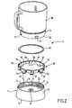
- the figure 2 illustrates the heating vessel 3 shown on the figure 1 .
- the heating vessel 3 comprises a base 10 and an annular side wall 20 of container removably mounted on the base 10.
- the base 10 has an annular portion 11 surrounding a heating base 12.
- the annular portion 11 is assembled with the heating base 12
- the base 10 may comprise a rotary working tool, not shown on the figure 2 .
- the heating base 12 has an axial opening 8.
- the annular portion 11 has an inner annular flange 13.
- the bottom heater 12 is connected to the inner annular collar 13.
- the annular portion 11 extends above the heating base 12.
- the annular portion 11 forms an upper annular wall 14 rising from the heating bottom 12.
- the upper annular wall 14 is peripheral.
- the annular portion 11 also extends below the heating bottom 12.
- the annular portion 11 forms a lower annular wall 15 extending below the heating bottom 12.
- the lower annular wall 15 is peripheral.
- Means 30 for holding the removable annular lateral container wall 20 are provided on the annular portion 11.
- the holding means 30 are designed to cooperate with an external face of the removable annular lateral container wall 20, as shown in FIG. figure 6 .
- the holding means 30 are arranged on the upper annular wall 14. More particularly, the holding means 30 comprise a locking ring 31 bayonet mounted movable relative to the upper annular wall 14.
- the locking ring 31 comprises lower legs 32 provided with external hooks 33 and the annular portion 11 has internal longitudinal slots 16 opening into an inner peripheral groove portion 17 of the upper annular wall 14.
- the locking ring 31 has internal longitudinal grooves 34 opening between two lower tabs 32 at a distance from one of said lower tabs.
- a lower edge 35 of the locking ring 31 adjacent to one of the internal longitudinal grooves 34 forms a retaining means for a lug 21 formed on the outer face of the lower portion of the removable annular side wall 20 container.
- a lateral face 36 of the lower lug adjacent to said lower edge 35 forms a lateral locking stop for said lug 21.
- the annular side wall advantageously comprises at least three lugs 21, and preferably four lugs 21, as shown in FIG. figure 2 .
- the annular portion 11 is advantageously made of plastic. According to a preferred embodiment illustrated on the Figures 3 to 6 and 9 , the part annular 11 comprises a piece overmolded around the heating bottom 12.
- the heating base 12 comprises a plate 50 associated with heating means 51.
- the heating means 51 are formed by a screen-printed heating element 52 arranged under the plate 50.
- One or more layers of dielectric insulation may be deposited between the plate 50 and the conductive tracks of the screen-printed heating element 52 and / or on the conductive tracks of the screen-printed heating element 52.
- the plate 50 is advantageously made of stainless steel, for example stainless steel type F17, 403 or 430.
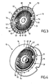
- the figure 3 illustrates the heating base 12 formed by the plate 50 carrying the screen-printed heating element 52.
- the screen-printed heating element 52 is made on the lower face of the plate 50.
- the plate 50 forms a disk.
- the thickness of the plate 50 is for example 1.2 mm, to facilitate the welding of a mass stud 53.
- the heating base 12 has a central portion 54 carrying the heating means 51 formed by the screen-printed heating element 52.
- the heating base 12 has a peripheral portion 55 advantageously comprising a raised edge 56 and cutouts 57.
- the raised edge 56 allows to improve the rigidity of said heating base 12.
- the cuts 57 make it easier to attach the annular portion 11 to the peripheral portion 55.
- the plate 50 advantageously has a swept area 58 between the central portion 54 and the peripheral portion 55 of the
- the resistive tracks of the screen-printed heating element 52 are surrounded by the embossed zone 58 and advantageously extend at a distance of at least 3 mm from the embossed zone 58.
- a central passage 59 is formed in the plate 50.
- the central passage 59 may advantageously have notches 60 as visible on the figure 3 and / or a raised edge. If desired the notches can be raised or not. The raised edge may be continuous or not.
- the resistive tracks of the serigraphed heating element 52 surround the central passage 59.
- the resistive tracks of the screen-printed heating element 52 are formed on an intermediate annular zone 61 of the heating base 12.
- the intermediate annular zone 61 surrounds a central zone 62 of the heating base 12 devoid of resistive tracks.
- the intermediate annular zone 61 is surrounded by a peripheral zone 63 of the heating base 12 also lacking resistive tracks.
- the intermediate annular zone 61 and the central zone 62 are formed on the central portion 54 of the heating base 12.
- the peripheral zone 63 extends on the periphery of the central portion 54 as well as on the embossed zone 58 and on the peripheral portion 55 .
- the figure 4 illustrates the base 10 after overmolding of the annular portion 11 around the heating base 12.
- the annular portion 11 is assembled with the peripheral portion 55 of the heating base 12.
- the annular portion 11 is made of material (s) adapted (s) to temperatures reached by the peripheral portion 55 of the heating base 12.
- the annular portion 11 may for example be made of glass filled polypropylene, in particular for the heating means 51 having a power of the order of 1000 W associated with the plate 50 made of stainless steel.
- the annular portion 11 may also be made of PBT, in particular for heating means 51 having a higher amount, up to 3000 W, associated with the plate 50 made of stainless steel.
- the annular portion 11 of the base 10 is overmolded around the central portion 54 of the heating base 12.
- the annular portion 11 is overmolded on the peripheral portion 55 around the embossed zone 58.
- the annular portion 11 is secured annularly with the peripheral portion 55 of the heating bottom 12.
- the peripheral zone 63 forms a thermal brake between the heating means 51 and the annular portion 11.
- the holding means 30 are formed inside the annular wall upper portion 14 of the annular portion 11, as visible on the figure 2 .
- the annular portion 11 forms an annular thermal brake made of a non-metallic material between the holding means 30 and the peripheral portion 55 of the heating base 12 and thus makes it possible to avoid the dispersion of the heat coming from the heating base 12 towards the annular side wall 20 removable container.
- a central core 64 is overmolded in the central zone 62 around the central passage 59.
- the notches 60 (visible on the figure 3 ) facilitate the attachment of the central core 64 to the central portion 54 of the heating base 12.
- the central zone 62 forms a thermal brake between the heating means 51 and the central core 64.
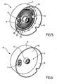
- the figure 5 illustrates the base 10 after mounting a connector 9 on the underside of the heating base 12.
- the connector 9 is arranged around the ground stud 53.
- the screen-printed heating element 52 advantageously has a saving at the central core 64.
- the heating base 12 is devoid of resistive tracks belonging to the screen-printed heating element 52.
- the central zone of the screen-printed heating element is usually one of the hottest areas.
- the resistive tracks of the screen-printed heating element 52 advantageously extend at a distance of at least 3 mm from the central core 64, for example at a distance of 10 mm.
- the figure 6 illustrates the base 10 after adding polymer material 65 to cover the underside of the plate 50 carrying the screen-printed heating element 52.
- FIGS 7 and 8 illustrate other annular side walls 24, 26 of container may be mounted on the base 10 in place of the annular side wall 20.
- the annular side walls 20, 24, 26 container are of different geometry.
- the annular side walls 20, 24, 26 of the container may also be made of different materials, for example example plastic, stainless steel, glass or even ceramic.
- the figure 9 illustrates a heating container 37 of household appliance for food preparation and / or drinks, comprising the base 10 illustrated on the Figures 1 to 6 and the annular annular container wall 26 illustrated on the figure 8 , mounted removably on said base 10 by means of the locking ring 31.
- the annular portion 11 forms an outer wall of the heating container 37.
- the annular side wall 26 of the container is mounted inside the annular portion 11.
- the heating base 12 has means 18 for receiving a rotary working tool 6.
- the receiving means 18 of the rotary working tool 6 comprise a driving element 19.
- the driving element 19 passes through the axial opening 8 of the heating bottom 12.
- the driving element 19 is mounted in the central core 64.
- the rotary working tool 6 can be fixed to the upper part of the driving element 19 or on the contrary be removable relative to the driving element 19, as shown in FIG. figure 9 .
- a seal 40 is interposed between the base 10 and a lower annular edge 22 of the annular side wall 20, 26 removable container.
- the seal 40 rests on the annular portion 11 at the periphery of the heating base 12.
- the seal 40 is placed in compression between the annular portion 11 and the lower annular edge 22 of the annular lateral wall 20, 26 of removable container by means of the crown In particular, the seal 40 rests on the inner annular flange 13.
- the seal 40 could in particular be overmoulded on the lower annular edge 22 of the removable annular side wall 20, 24, 26 of the container.
- the seal 40 is advantageously arranged at a distance from the heating means 51.
- the seal 40 is disposed at the periphery of the conductive tracks of the screen-printed heating element 52.
- the base 10 can be used with each of the annular side walls 20, 24, 26.
- the base 10 forms in particular a heating device 5 for the heating container 3 of the food and / or drink preparation appliance illustrated on the figure 1 , or for the heating vessel 37 illustrated on the figure 9 .
- the appliance for food and / or drink preparation illustrated on the figure 1 can receive a heating container formed by the base 10 and one of the annular side walls 20, 24, 26.
- the appliance for preparing food and / or drinks receiving the heating container 37 formed by the base 10 and the annular wall 26 represented on the figure 9 comprises a rotary working tool 6 disposed in the heating vessel 37, and a housing 7 having drive means for the rotary working tool 6, the housing 7 being formed by the base 1 shown in FIG. figure 1 .
- the annular side walls 20, 24, 26 and the base 10 form a set of accessories for household appliances for preparing food and / or drinks.
- the figure 10 illustrates a heating vessel 38 of a food and / or beverage preparation appliance, wherein the annular sidewall 26 shown in FIGS. figures 8 and 9 is mounted on a base 10 'having a central core 64' forming a chimney 8 '.
- the base 10 ' has an annular portion 11' surrounding a heating base 12 '.
- the annular portion 11 ' is identical to the annular portion 11 of the base 10.
- the annular portion 11' forms an outer wall of the heating vessel 38.
- the annular portion 11 ' is secured annularly with the peripheral portion 55' of the bottom heating element 12 'in a manner identical to the assembly of the annular portion 11 with the heating base 12 of the base 10.
- the heating base 12' is identical to the heating base 12 with the exception of the central core 64 'replacing the central core 64.
- the annular portion 11 ' forms an annular thermal brake made of non-metallic material between the holding means 30' and the peripheral portion 55 'of the heating base 12'.
- the base 10 ' has a connector 9'.
- the base 10 ' has means 18' for receiving a rotary working tool (not shown in FIG. figure 6 ).
- the receiving means 18 ' comprise a guiding member 19' provided for receiving said rotary working tool.
- the guide member 19 ' is formed by the chimney 8' rising from the heating bottom 12 '.
- Holding means 30 'of the removable annular side wall 26 of the container are provided on the annular portion 11'.
- the holding means 30 ' are disposed on the upper annular wall 14' of the annular portion 11 '.
- the holding means 30 ' comprise a locking ring 31' bayonet mounted movable relative to the upper annular wall 14 '.
- the annular side wall 26 of the container is mounted inside the annular portion 11 '.
- the base 10 ' can be used with each of the annular side walls 20, 24, 26.
- the base 10' forms in particular a heating device 5 'for the heating vessel 38 illustrated in FIG. figure 10 .
- the annular side walls 20, 24, 26 and the base 10 form a set of accessories for household appliances for preparing food and / or drinks.
- the appliance for food and / or drink preparation illustrated on the figure 11 comprises a base 101 forming a base 102 receiving a heating vessel 103 associated with a cover 104, and a housing 107 comprising means for driving a rotary working tool 106.
- the appliance for food and / or drink preparation illustrated on the figure 11 differs from the food and / or drink appliance shown on the display. figure 1 in that the housing 107 is formed by the cover 104.
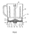
- the figure 12 illustrates the heating vessel 103 shown on the figure 11 receiving the rotary working tool 106.
- the heating container 103 has a base 110 and an annular side wall 120 of the container mounted on the base 110.
- the base 110 has an annular portion 111 surrounding a heating base 112.
- the annular portion 111 forms an outer wall of the heating vessel 103.
- the base 110 comprises a connector 109 advantageously arranged in the central position.
- the heating base 112 comprises a plate 150 carrying a screen-printed heating element 152.
- the plate 150 is advantageously identical to the plate 50.
- the screen-printed heating element 152 can easily have resistive tracks of different design and / or different power of the drawing and / or the power of the resistive tracks of the screen-printed heating element 52.
- Of the polymeric material 165 advantageously covers the bottom face of the heating base 112.
- the annular portion 111 is assembled with the peripheral portion 155 of the heating base 112 in an identical manner to the assembly of the annular portion 11 with the heating base 12 of the base 10.
- the annular portion 111 forms an annular thermal brake made of non-metallic material between the annular side wall 120 of the container and the peripheral portion 155 of the heating base 112.
- the base 110 is devoid of rotary working tool.
- the heating base 112 has receiving means 118 of the rotary working tool 106, visible on the figure 12 .
- the receiving means 118 of the rotary working tool 106 comprise a guide member 119. As shown in FIG. figure 12 , the guide member 119 is formed by an axis provided to receive the rotary working tool 106.
- the guide member 119 may be formed by a conformation formed on the upper face of the heating base 112, this conformation receiving a support element of the rotary working tool.
- said support member may be rotatably mounted relative to the main portion of the rotary working tool carrying the working member; said support member being immobilizable, in particular in rotation, relative to the base 110.
- the annular side wall 120 of the container is fixed to the annular portion 111, for example by gluing.
- a seal 140 is advantageously interposed between the base 110 and a lower annular edge 122 of the annular side wall 120 of the container.
- the position of the seal 140 is identical to the position of the seal 40. If desired the seal 140 may be overmolded on the lower annular edge 122 of the annular side wall 120 of the container.
- the figure 13 illustrates a heating vessel 203 receiving the rotary working tool 106 illustrated on the figure 12 .
- the heating vessel 203 may be used with the base 101, the lid 104, and the rotary work tool 106 of the food and / or beverage preparation appliance illustrated in FIG. figure 11 .
- the heating vessel 203 has a base 210 and an annular side wall 220 of container mounted on the base 210.
- the heating vessel 203 illustrated on the figure 13 differs from the heating vessel 103 illustrated on the figures 11 and 12 in that the annular side wall 220 of the container is removable.
- the base 210 forms a heating device 205 for the heating vessel 203 of the appliance for preparing food and / or drinks illustrated in FIG. figure 11 .
- the heating device 205 has an annular portion 211 surrounding a heating bottom 212.
- the annular portion 211 forms an outer wall of the heating vessel 203.
- the annular portion 211 is assembled with the peripheral portion 255 of the heating bottom 212 in a manner identical to the assembly of the annular portion 11 with the heating base 12 of the base 10.
- the heating base 212 is identical to the heating base 112 illustrated on the figure 12 .
- the annular portion 211 forms an annular thermal brake made of non-metallic material between the holding means 230 and the peripheral portion 255 of the heating bottom 212.
- the heating base 212 comprises a plate 250 carrying a screen-printed heating element 252.
- the plate 250 is advantageously identical to the plate 50.
- the screen-printed heating element 252 can easily have resistive tracks of different design and / or different power from the design and / or the power of the resistive tracks of the screen-printed heating element 52 and / or the screen-printed heating element 152.
- the heating base 212 comprises receiving means 218 of the rotary working tool 106.
- the receiving means 218 comprise a guide member 219.
- the polymer 265 advantageously covers the bottom face of the heating base 212.
- Retaining means 230 of the removable annular side wall 220 of the container are provided on the annular portion 111.
- the holding means 230 are arranged on the upper annular wall 214 rising from the heating bottom 212.
- the holding means 230 define a helical path for a screw connection with conformations 229 provided on the removable annular side wall 220 of the container.
- the annular removable side wall 220 of container is mounted inside the annular portion 211.
- a seal 240 is advantageously interposed between the base 210 and a lower annular edge 222 of the removable annular side wall 220 of the container.
- the position of the seal 240 is identical to the position of the seal 40.
- annular container side walls may be used with the base 210.
- the heating base 12; 12 '; 112; 212 and / or the annular portion 11; 11 '; 111; 211 and / or the annular side wall 20; 24; 26; 120; 220 container does not necessarily (not) have a circular geometry.
- the plate 50; 150; 250 is not necessarily made of stainless steel, but may in particular be made of aluminum or glass.
- the plate 50; 150; 250 may have a perforated periphery and / or cut, to facilitate the connection with the annular portion 11; 11 '; 111; 211.
- the power of the heating base 12; 12 ';112; 212 can be adapted to the envisaged uses, with for example a power of heating of the order of 500 W to 1200 W for a food processor type food preparation appliance having a rotary working tool, and up to 3000 W for a kettle type of beverage preparation apparatus usually without rotary working tool.
- the heating base 12; 12 ';112; 212 may have several power levels.
- the heating means 51 are not necessarily formed by a screen-printed heating element 52; 152; 252.
- the different means of receiving a rotary working tool can be combined with the different means of assembly between the base and the container side wall.
- the heating device or the heating container of an appliance for food preparation and / or drinks according to the invention may be devoid of reception means of a rotating work tool.
- the appliance for preparing food and / or drinks according to the invention can then, if desired, be devoid of a housing comprising means for driving a rotary working tool.
- the annular side wall 20; 24; 26; 120; 220 container is not necessarily mounted within the annular portion 11; 11 '; 111; 211.
- the annular portion 11; 11 ';111; 211 may in particular have a metal outer covering.
- at least the portion of the annular portion 11; 11 ';111; 211 connecting the holding means 30; 30'; 230 or the container 120 to the peripheral portion 55; 55 ';155; 255 of the heating bottom 12; 12 ';112; 212 is made of plastic.
Landscapes
- Engineering & Computer Science (AREA)
- Food Science & Technology (AREA)
- Mechanical Engineering (AREA)
- Cookers (AREA)
Claims (19)
- Heizvorrichtung (5; 5'; 205) für einen Heizbehälter (3; 37; 38; 203) eines Elektrohaushaltsgerätes für die Zubereitung von Lebensmitteln und/oder Getränken, wobei die Heizvorrichtung (5; 5'; 205) einen ringförmigen Teil (11; 11'; 211) umfasst, der in der Art eines Ringes mit einem umlaufenden Teil (55; 55'; 255) eines Heizbodens (12; 12'; 212) fest verbunden ist, wobei Haltemittel (30; 30'; 230) einer abnehmbaren, ringförmigen Behälterseitenwand (20; 24; 26; 220) auf dem ringförmigen Teil (11; 11'; 211) vorgesehen sind, dadurch gekennzeichnet, dass der ringförmige Teil (11; 11'; 211) eine obere ringförmige Wand (14; 14'; 214) bildet, die ausgehend vom Heizboden (12; 12'; 212) emporragt.
- Heizvorrichtung (5; 5'; 205) nach Anspruch 1, dadurch gekennzeichnet, dass mindestens jener Abschnitt des ringförmigen Teils (11; 11'; 211), der die Haltemittel (30; 30'; 230) mit dem umlaufenden Teil (55; 55'; 255) des Heizbodens (12; 12'; 212) verbindet, aus Kunststoffmaterial hergestellt ist.
- Heizvorrichtung (5; 5'; 205) nach einem der Ansprüche 1 oder 2, dadurch gekennzeichnet, dass der ringförmige Teil (11; 11'; 211) ein Stück umfasst, das um den Heizboden (12; 12'; 212) herumgeformt ist.
- Heizvorrichtung (5; 5'; 205) nach einem der Ansprüche 1 bis 3, dadurch gekennzeichnet, dass der Heizboden (12; 12'; 212) eine Platte (50; 250) umfasst, die ein Siebdruck-Heizelement (52; 252) trägt.
- Heizvorrichtung (5; 5'; 205) nach einem der Ansprüche 1 bis 4, dadurch gekennzeichnet, dass sich der ringförmige Teil (11; 11'; 211) unterhalb des Heizbodens (12; 12'; 212) erstreckt.
- Heizvorrichtung (5; 5'; 205) nach einem der Ansprüche 1 bis 5, dadurch gekennzeichnet, dass die Haltemittel (30; 30'; 230) auf der oberen ringförmigen Wand (14; 14'; 214) angeordnet sind.
- Heizvorrichtung (5; 5') nach Anspruch 6, dadurch gekennzeichnet, dass die Haltemittel (30; 30') einen Verriegelungskranz (31; 31') mit Bajonettverschluss umfassen, der in Bezug auf die obere ringförmige Wand (14; 14') beweglich befestigt ist.
- Heizvorrichtung (205) nach Anspruch 6, dadurch gekennzeichnet, dass die Haltemittel (230) einen spiralförmigen Pfad definieren.
- Heizvorrichtung (5; 5'; 205) nach einem der Ansprüche 1 bis 8, dadurch gekennzeichnet, dass der Heizboden (12; 12'; 212) Mittel zur Aufnahme (18; 18'; 218) eines drehenden Arbeitswerkzeuges (6; 206) aufweist.
- Heizvorrichtung (5) nach Anspruch 9, dadurch gekennzeichnet, dass die Aufnahmemittel (18) ein Antriebselement (19) umfassen.
- Heizvorrichtung (5'; 205) nach Anspruch 9, dadurch gekennzeichnet, dass die Aufnahmemittel (18'; 218) ein Führungselement (19'; 219) umfassen.
- Heizbehälter (3; 37; 38; 203) eines Elektrohaushaltsgerätes für die Zubereitung von Lebensmitteln und/oder Getränken, umfassend einen Sockel (10; 10'; 210) und eine ringförmige Behälterseitenwand (20; 24; 26; 220), die abnehmbar auf dem Sockel (10; 10'; 210) befestigt ist, dadurch gekennzeichnet, dass der Sockel (10; 10'; 210) eine Heizvorrichtung (5; 5'; 205) nach einem der Ansprüche 1 bis 11 bildet.
- Heizbehälter (103) eines Elektrohaushaltsgerätes für die Zubereitung von Lebensmitteln und/oder Getränken, dadurch gekennzeichnet, dass er einen Sockel (110) und eine ringförmige Behälterseitenwand (120) aufweist, die auf dem Sockel (110) befestigt ist, wobei der Sockel (110) einen ringförmigen Teil (111) umfasst, der in der Art eines Ringes mit einem umlaufenden Teil (155) eines Heizbodens (12; 12'; 212) fest verbunden ist, wobei die ringförmige Behälterseitenwand (120) am ringförmigen Teil (111) befestigt ist, wobei der ringförmige Teil (111) eine obere ringförmige Wand bildet, die ausgehend vom Heizboden (112) emporragt.
- Elektrohaushaltsgerät für die Zubereitung von Lebensmitteln und/oder Getränken, umfassend einen Heizbehälter (3; 37; 38; 103; 203), dadurch gekennzeichnet, dass der Heizbehälter (3; 37; 38; 103; 203) einem der Ansprüche 12 oder 13 entspricht.
- Einheit aus Zubehörteilen eines Elektrohaushaltsgerätes für die Zubereitung von Lebensmitteln und/oder Getränken, umfassend einen Sockel (10; 10'; 110; 210) und mindestens zwei ringförmige Behälterseitenwände (20; 24; 26; 110; 220), die auf dem Sockel (10; 10'; 110; 210) befestigt werden können, dadurch gekennzeichnet, dass der Sockel (10; 10'; 110; 210) eine Heizvorrichtung (5; 5'; 105; 205) nach einem der Ansprüche 1 bis 11 bildet.
- Einheit aus Zubehörteilen eines Elektrohaushaltsgerätes für die Zubereitung von Lebensmitteln und/oder Getränken nach Anspruch 15, dadurch gekennzeichnet, dass sie zwei ringförmige Behälterseitenwände (20; 24; 26; 110; 220) mit unterschiedlichen Formen umfasst.
- Einheit aus Zubehörteilen eines Elektrohaushaltsgerätes für die Zubereitung von Lebensmitteln und/oder Getränken nach einem der Ansprüche 15 oder 16, dadurch gekennzeichnet, dass sie zwei ringförmige Behälterseitenwände (20; 24; 26; 110; 220) umfasst, die aus unterschiedlichen Materialien hergestellt sind.
- Elektrohaushaltsgerät für die Zubereitung von Lebensmitteln und/oder Getränken, umfassend einen Heizbehälter (3; 37; 38; 103; 203), dadurch gekennzeichnet, dass der Heizbehälter (3; 37; 38; 103; 203) aus einer Einheit aus Zubehörteilen eines Elektrohaushaltsgerätes für die Zubereitung von Lebensmitteln und/oder Getränken nach einem der Ansprüche 15 bis 17 hergestellt ist.
- Elektrohaushaltsgerät für die Zubereitung von Lebensmitteln und/oder Getränken nach einem der Ansprüche 14 oder 18, dadurch gekennzeichnet, dass es ein drehendes Arbeitswerkzeug (6; 106; 206), das im Heizbehälter (3; 37; 38; 103; 203) angeordnet ist, und ein Gehäuse (7; 107) umfasst, das Antriebsmittel für das drehende Arbeitswerkzeug (6; 106; 206) umfasst.
Applications Claiming Priority (2)
| Application Number | Priority Date | Filing Date | Title |
|---|---|---|---|
| FR0709075A FR2925275A1 (fr) | 2007-12-21 | 2007-12-21 | Recipient chauffant et dispositif chauffant pour un appareil electromenager de preparation d'aliments et/ou de boissons |
| PCT/FR2008/001802 WO2009103904A2 (fr) | 2007-12-21 | 2008-12-19 | Recipient chauffant et dispositif chauffant pour un appareil electromenager de preparation d'aliments et/ou de boissons |
Publications (2)
| Publication Number | Publication Date |
|---|---|
| EP2240054A2 EP2240054A2 (de) | 2010-10-20 |
| EP2240054B1 true EP2240054B1 (de) | 2011-07-06 |
Family
ID=39580621
Family Applications (1)
| Application Number | Title | Priority Date | Filing Date |
|---|---|---|---|
| EP08872611A Not-in-force EP2240054B1 (de) | 2007-12-21 | 2008-12-19 | Erwärmungsbehälter und erwärmungsvorrichtung für ein haushaltsgerät für die zubereitung von speisen und/oder getränken |
Country Status (6)
| Country | Link |
|---|---|
| EP (1) | EP2240054B1 (de) |
| CN (1) | CN101902940B (de) |
| AT (1) | ATE515216T1 (de) |
| ES (1) | ES2368882T3 (de) |
| FR (1) | FR2925275A1 (de) |
| WO (1) | WO2009103904A2 (de) |
Cited By (3)
| Publication number | Priority date | Publication date | Assignee | Title |
|---|---|---|---|---|
| US10085599B2 (en) | 2014-12-19 | 2018-10-02 | Whirlpool Corporation | Multi-cook and food processing prep product |
| CN109480622A (zh) * | 2018-12-06 | 2019-03-19 | 九阳股份有限公司 | 一种电水壶 |
| EP4292483A1 (de) * | 2022-06-13 | 2023-12-20 | BSH Hausgeräte GmbH | Schale für eine lebensmittelverarbeitungsvorrichtung |
Families Citing this family (7)
| Publication number | Priority date | Publication date | Assignee | Title |
|---|---|---|---|---|
| US10449685B2 (en) | 2010-04-29 | 2019-10-22 | Whirlpool Corporation | Food processor with adjustable blade assembly |
| US8720325B2 (en) | 2010-04-29 | 2014-05-13 | Whirlpool Corporation | Food processor with a lockable adjustable blade assembly |
| US8800905B2 (en) | 2011-02-08 | 2014-08-12 | Main Power Electrical Factory Ltd. | Mixing vessel |
| FR2974992B1 (fr) * | 2011-05-13 | 2013-05-03 | Seb Sa | Recipient de chauffe avec plusieurs pistes resistives serigraphiees, appareil transportable comprenant un tel recipient de chauffe et procede d'obtention du recipient de chauffe |
| FR2980349B1 (fr) | 2011-09-28 | 2013-10-25 | Hameur Sa | Appareil de traitement alimentaire |
| US10045664B2 (en) * | 2014-07-10 | 2018-08-14 | Vita-Mix Management Corporation | Blade assembly with safety guard |
| FR3114953B1 (fr) * | 2020-10-08 | 2022-10-28 | Hameur | Appareil de préparation culinaire, cuve et adaptateur pour le constituer |
Family Cites Families (10)
| Publication number | Priority date | Publication date | Assignee | Title |
|---|---|---|---|---|
| FR2748645B1 (fr) * | 1996-05-14 | 1998-07-24 | Seb Sa | Bouilloire electrique a plaque metallique de chauffe |
| EP1090534B1 (de) * | 1998-06-03 | 2003-07-30 | Strix Limited | Gefässe zum erhitzen von flüssigkeiten |
| GB2344506B (en) * | 1998-12-08 | 2002-10-02 | Otter Controls Ltd | Improvements relating to electrically heated vessels |
| GB2363055B (en) * | 2000-06-05 | 2004-02-25 | Otter Controls Ltd | Improvements relating to the assembly of heating elements into liquid heating vessels |
| GB2364890A (en) * | 2000-07-25 | 2002-02-13 | Otter Controls Ltd | Securing planar heating element in liquid heating vessel |
| DE20213139U1 (de) * | 2002-08-27 | 2004-01-15 | 3Rd Angle (U.K.) Ltd., Highley | Elektrischer Wasserkocher |
| CN2576015Y (zh) * | 2002-10-19 | 2003-10-01 | 罗晓峰 | 豆浆机 |
| GB0501354D0 (en) * | 2005-01-21 | 2005-03-02 | Strix Ltd | Liquid heating vessels having heated basis |
| US20060286255A1 (en) | 2005-06-18 | 2006-12-21 | Zhaoxia Xu | Automated Soup Making Apparatus |
| KR100770641B1 (ko) * | 2006-05-26 | 2007-10-30 | 김홍배 | 간접 가열 방식의 조리 장치 |
-
2007
- 2007-12-21 FR FR0709075A patent/FR2925275A1/fr active Pending
-
2008
- 2008-12-19 AT AT08872611T patent/ATE515216T1/de not_active IP Right Cessation
- 2008-12-19 CN CN2008801218815A patent/CN101902940B/zh active Active
- 2008-12-19 WO PCT/FR2008/001802 patent/WO2009103904A2/fr not_active Ceased
- 2008-12-19 ES ES08872611T patent/ES2368882T3/es active Active
- 2008-12-19 EP EP08872611A patent/EP2240054B1/de not_active Not-in-force
Cited By (3)
| Publication number | Priority date | Publication date | Assignee | Title |
|---|---|---|---|---|
| US10085599B2 (en) | 2014-12-19 | 2018-10-02 | Whirlpool Corporation | Multi-cook and food processing prep product |
| CN109480622A (zh) * | 2018-12-06 | 2019-03-19 | 九阳股份有限公司 | 一种电水壶 |
| EP4292483A1 (de) * | 2022-06-13 | 2023-12-20 | BSH Hausgeräte GmbH | Schale für eine lebensmittelverarbeitungsvorrichtung |
Also Published As
| Publication number | Publication date |
|---|---|
| CN101902940B (zh) | 2012-10-17 |
| WO2009103904A2 (fr) | 2009-08-27 |
| EP2240054A2 (de) | 2010-10-20 |
| CN101902940A (zh) | 2010-12-01 |
| WO2009103904A3 (fr) | 2009-10-22 |
| FR2925275A1 (fr) | 2009-06-26 |
| ES2368882T3 (es) | 2011-11-23 |
| ATE515216T1 (de) | 2011-07-15 |
Similar Documents
| Publication | Publication Date | Title |
|---|---|---|
| WO2009103904A2 (fr) | Recipient chauffant et dispositif chauffant pour un appareil electromenager de preparation d'aliments et/ou de boissons | |
| EP2237710B1 (de) | Erwärmungsbehälter für ein haushaltsgerät für die zubereitung von speisen und/oder getränken | |
| EP2016878B1 (de) | Schnellkochtopf mit einem festen Griff am Topf | |
| EP2248452B1 (de) | Kochgerät mit Mittel zum Umrühren | |
| EP2434933B1 (de) | Elektrhaushaltsgerät für speisenzubereitung mit eienr basis zur aufnahme eines arbeitsgefässes mit einer wärmeplatte | |
| WO2011077038A1 (fr) | Appareil electromenager de preparation culinaire comportant une vis de pressage et un dispositif de predecoupe | |
| FR3019022A1 (fr) | Appareil de cuisson d'aliments sous pression a baionnettes inversees et methode de fabrication afferente | |
| EP1900315B1 (de) | Stabmixgerät, das ein Arbeitswerkzeug in Form einer Archimedischen Schraube umfasst | |
| EP2147624A1 (de) | Schüssel für Küchenmaschine mit verbesserter Dichtung | |
| EP1117318B1 (de) | Elektrogerät zum erhitzen von flüssigkeiten mit einem heizboden und glaswänden | |
| EP3424378B1 (de) | Innenbehälter, zubehörteil zur essenszubereitung und elektrohaushaltsgerät zur essenszubereitung, das einen solchen innenbehälter umfasst | |
| EP2574258B1 (de) | Elektrohaushaltsgerät mit Aufheizfunktion, insbesondere für die Herstellung von Saucen | |
| EP2937027B1 (de) | Elektrohaushaltsgerät zur essenszubereitung, das einen entfernbaren behälter umfasst, der durch eine einfache verschiebungsbewegung auf einem gehäuse abgestellt werden kann | |
| EP3528678B1 (de) | Elektrische haushaltsaufwärmvorrichtung zur zubereitung von lebensmitteln mit einem dampfkorb | |
| FR3051651A1 (fr) | Outil de petrissage pour appareil electromenager de preparation culinaire | |
| EP1435814B1 (de) | Ausguss für maschine für heisse getränke und maschine für heisse getränke mit ausguss | |
| EP3424381B1 (de) | Innenbehälter, zubehörteil zur essenszubereitung und elektrohaushaltsgerät zur essenszubereitung, das einen solchen innenbehälter umfasst | |
| EP1380241B1 (de) | Gussgriff für einen Glasbehälter | |
| FR2853413A1 (fr) | Capteur de temperature a faible cout pour appareil electromenager | |
| FR2690903A1 (fr) | Organe de protection contre la chaleur. | |
| EP3311718A1 (de) | Beheizbares elektrohaushaltsgerät zur essenszubereitung, das eine ringdichtung umfasst | |
| FR3095934A1 (fr) | récipients à doubles parois | |
| WO2006097610A1 (fr) | Article culinaire a element d'appui pour empilage | |
| EP1426003A1 (de) | Elektrisches Kochgerät mit einem feststehenden in einem Gehäuse angeordneten Behälter |
Legal Events
| Date | Code | Title | Description |
|---|---|---|---|
| PUAI | Public reference made under article 153(3) epc to a published international application that has entered the european phase |
Free format text: ORIGINAL CODE: 0009012 |
|
| 17P | Request for examination filed |
Effective date: 20100713 |
|
| AK | Designated contracting states |
Kind code of ref document: A2 Designated state(s): AT BE BG CH CY CZ DE DK EE ES FI FR GB GR HR HU IE IS IT LI LT LU LV MC MT NL NO PL PT RO SE SI SK TR |
|
| AX | Request for extension of the european patent |
Extension state: AL BA MK RS |
|
| GRAP | Despatch of communication of intention to grant a patent |
Free format text: ORIGINAL CODE: EPIDOSNIGR1 |
|
| DAX | Request for extension of the european patent (deleted) | ||
| GRAS | Grant fee paid |
Free format text: ORIGINAL CODE: EPIDOSNIGR3 |
|
| GRAA | (expected) grant |
Free format text: ORIGINAL CODE: 0009210 |
|
| AK | Designated contracting states |
Kind code of ref document: B1 Designated state(s): AT BE BG CH CY CZ DE DK EE ES FI FR GB GR HR HU IE IS IT LI LT LU LV MC MT NL NO PL PT RO SE SI SK TR |
|
| REG | Reference to a national code |
Ref country code: GB Ref legal event code: FG4D Free format text: NOT ENGLISH |
|
| REG | Reference to a national code |
Ref country code: CH Ref legal event code: EP |
|
| REG | Reference to a national code |
Ref country code: IE Ref legal event code: FG4D Free format text: LANGUAGE OF EP DOCUMENT: FRENCH |
|
| REG | Reference to a national code |
Ref country code: DE Ref legal event code: R096 Ref document number: 602008008171 Country of ref document: DE Effective date: 20110825 |
|
| REG | Reference to a national code |
Ref country code: NL Ref legal event code: VDEP Effective date: 20110706 |
|
| REG | Reference to a national code |
Ref country code: ES Ref legal event code: FG2A Ref document number: 2368882 Country of ref document: ES Kind code of ref document: T3 Effective date: 20111123 |
|
| PG25 | Lapsed in a contracting state [announced via postgrant information from national office to epo] |
Ref country code: SI Free format text: LAPSE BECAUSE OF FAILURE TO SUBMIT A TRANSLATION OF THE DESCRIPTION OR TO PAY THE FEE WITHIN THE PRESCRIBED TIME-LIMIT Effective date: 20110706 |
|
| REG | Reference to a national code |
Ref country code: AT Ref legal event code: MK05 Ref document number: 515216 Country of ref document: AT Kind code of ref document: T Effective date: 20110706 |
|
| PG25 | Lapsed in a contracting state [announced via postgrant information from national office to epo] |
Ref country code: SE Free format text: LAPSE BECAUSE OF FAILURE TO SUBMIT A TRANSLATION OF THE DESCRIPTION OR TO PAY THE FEE WITHIN THE PRESCRIBED TIME-LIMIT Effective date: 20110706 Ref country code: NL Free format text: LAPSE BECAUSE OF FAILURE TO SUBMIT A TRANSLATION OF THE DESCRIPTION OR TO PAY THE FEE WITHIN THE PRESCRIBED TIME-LIMIT Effective date: 20110706 Ref country code: LT Free format text: LAPSE BECAUSE OF FAILURE TO SUBMIT A TRANSLATION OF THE DESCRIPTION OR TO PAY THE FEE WITHIN THE PRESCRIBED TIME-LIMIT Effective date: 20110706 Ref country code: PT Free format text: LAPSE BECAUSE OF FAILURE TO SUBMIT A TRANSLATION OF THE DESCRIPTION OR TO PAY THE FEE WITHIN THE PRESCRIBED TIME-LIMIT Effective date: 20111107 Ref country code: FI Free format text: LAPSE BECAUSE OF FAILURE TO SUBMIT A TRANSLATION OF THE DESCRIPTION OR TO PAY THE FEE WITHIN THE PRESCRIBED TIME-LIMIT Effective date: 20110706 Ref country code: IS Free format text: LAPSE BECAUSE OF FAILURE TO SUBMIT A TRANSLATION OF THE DESCRIPTION OR TO PAY THE FEE WITHIN THE PRESCRIBED TIME-LIMIT Effective date: 20111106 Ref country code: NO Free format text: LAPSE BECAUSE OF FAILURE TO SUBMIT A TRANSLATION OF THE DESCRIPTION OR TO PAY THE FEE WITHIN THE PRESCRIBED TIME-LIMIT Effective date: 20111006 Ref country code: HR Free format text: LAPSE BECAUSE OF FAILURE TO SUBMIT A TRANSLATION OF THE DESCRIPTION OR TO PAY THE FEE WITHIN THE PRESCRIBED TIME-LIMIT Effective date: 20110706 |
|
| REG | Reference to a national code |
Ref country code: IE Ref legal event code: FD4D |
|
| PG25 | Lapsed in a contracting state [announced via postgrant information from national office to epo] |
Ref country code: PL Free format text: LAPSE BECAUSE OF FAILURE TO SUBMIT A TRANSLATION OF THE DESCRIPTION OR TO PAY THE FEE WITHIN THE PRESCRIBED TIME-LIMIT Effective date: 20110706 Ref country code: AT Free format text: LAPSE BECAUSE OF FAILURE TO SUBMIT A TRANSLATION OF THE DESCRIPTION OR TO PAY THE FEE WITHIN THE PRESCRIBED TIME-LIMIT Effective date: 20110706 Ref country code: GR Free format text: LAPSE BECAUSE OF FAILURE TO SUBMIT A TRANSLATION OF THE DESCRIPTION OR TO PAY THE FEE WITHIN THE PRESCRIBED TIME-LIMIT Effective date: 20111007 Ref country code: LV Free format text: LAPSE BECAUSE OF FAILURE TO SUBMIT A TRANSLATION OF THE DESCRIPTION OR TO PAY THE FEE WITHIN THE PRESCRIBED TIME-LIMIT Effective date: 20110706 Ref country code: CY Free format text: LAPSE BECAUSE OF FAILURE TO SUBMIT A TRANSLATION OF THE DESCRIPTION OR TO PAY THE FEE WITHIN THE PRESCRIBED TIME-LIMIT Effective date: 20110706 |
|
| PG25 | Lapsed in a contracting state [announced via postgrant information from national office to epo] |
Ref country code: SK Free format text: LAPSE BECAUSE OF FAILURE TO SUBMIT A TRANSLATION OF THE DESCRIPTION OR TO PAY THE FEE WITHIN THE PRESCRIBED TIME-LIMIT Effective date: 20110706 Ref country code: CZ Free format text: LAPSE BECAUSE OF FAILURE TO SUBMIT A TRANSLATION OF THE DESCRIPTION OR TO PAY THE FEE WITHIN THE PRESCRIBED TIME-LIMIT Effective date: 20110706 Ref country code: IE Free format text: LAPSE BECAUSE OF FAILURE TO SUBMIT A TRANSLATION OF THE DESCRIPTION OR TO PAY THE FEE WITHIN THE PRESCRIBED TIME-LIMIT Effective date: 20110706 |
|
| PLBE | No opposition filed within time limit |
Free format text: ORIGINAL CODE: 0009261 |
|
| STAA | Information on the status of an ep patent application or granted ep patent |
Free format text: STATUS: NO OPPOSITION FILED WITHIN TIME LIMIT |
|
| PG25 | Lapsed in a contracting state [announced via postgrant information from national office to epo] |
Ref country code: EE Free format text: LAPSE BECAUSE OF FAILURE TO SUBMIT A TRANSLATION OF THE DESCRIPTION OR TO PAY THE FEE WITHIN THE PRESCRIBED TIME-LIMIT Effective date: 20110706 Ref country code: IT Free format text: LAPSE BECAUSE OF FAILURE TO SUBMIT A TRANSLATION OF THE DESCRIPTION OR TO PAY THE FEE WITHIN THE PRESCRIBED TIME-LIMIT Effective date: 20110706 Ref country code: RO Free format text: LAPSE BECAUSE OF FAILURE TO SUBMIT A TRANSLATION OF THE DESCRIPTION OR TO PAY THE FEE WITHIN THE PRESCRIBED TIME-LIMIT Effective date: 20110706 |
|
| 26N | No opposition filed |
Effective date: 20120411 |
|
| PG25 | Lapsed in a contracting state [announced via postgrant information from national office to epo] |
Ref country code: DK Free format text: LAPSE BECAUSE OF FAILURE TO SUBMIT A TRANSLATION OF THE DESCRIPTION OR TO PAY THE FEE WITHIN THE PRESCRIBED TIME-LIMIT Effective date: 20110706 |
|
| BERE | Be: lapsed |
Owner name: SEB S.A. Effective date: 20111231 |
|
| PG25 | Lapsed in a contracting state [announced via postgrant information from national office to epo] |
Ref country code: MC Free format text: LAPSE BECAUSE OF NON-PAYMENT OF DUE FEES Effective date: 20111231 |
|
| REG | Reference to a national code |
Ref country code: DE Ref legal event code: R097 Ref document number: 602008008171 Country of ref document: DE Effective date: 20120411 |
|
| PG25 | Lapsed in a contracting state [announced via postgrant information from national office to epo] |
Ref country code: BE Free format text: LAPSE BECAUSE OF NON-PAYMENT OF DUE FEES Effective date: 20111231 |
|
| PG25 | Lapsed in a contracting state [announced via postgrant information from national office to epo] |
Ref country code: MT Free format text: LAPSE BECAUSE OF FAILURE TO SUBMIT A TRANSLATION OF THE DESCRIPTION OR TO PAY THE FEE WITHIN THE PRESCRIBED TIME-LIMIT Effective date: 20110706 |
|
| PG25 | Lapsed in a contracting state [announced via postgrant information from national office to epo] |
Ref country code: LU Free format text: LAPSE BECAUSE OF NON-PAYMENT OF DUE FEES Effective date: 20111219 |
|
| PG25 | Lapsed in a contracting state [announced via postgrant information from national office to epo] |
Ref country code: BG Free format text: LAPSE BECAUSE OF FAILURE TO SUBMIT A TRANSLATION OF THE DESCRIPTION OR TO PAY THE FEE WITHIN THE PRESCRIBED TIME-LIMIT Effective date: 20111006 |
|
| REG | Reference to a national code |
Ref country code: CH Ref legal event code: PL |
|
| PG25 | Lapsed in a contracting state [announced via postgrant information from national office to epo] |
Ref country code: TR Free format text: LAPSE BECAUSE OF FAILURE TO SUBMIT A TRANSLATION OF THE DESCRIPTION OR TO PAY THE FEE WITHIN THE PRESCRIBED TIME-LIMIT Effective date: 20110706 |
|
| PG25 | Lapsed in a contracting state [announced via postgrant information from national office to epo] |
Ref country code: CH Free format text: LAPSE BECAUSE OF NON-PAYMENT OF DUE FEES Effective date: 20121231 Ref country code: LI Free format text: LAPSE BECAUSE OF NON-PAYMENT OF DUE FEES Effective date: 20121231 Ref country code: HU Free format text: LAPSE BECAUSE OF FAILURE TO SUBMIT A TRANSLATION OF THE DESCRIPTION OR TO PAY THE FEE WITHIN THE PRESCRIBED TIME-LIMIT Effective date: 20110706 |
|
| PGFP | Annual fee paid to national office [announced via postgrant information from national office to epo] |
Ref country code: ES Payment date: 20141224 Year of fee payment: 7 Ref country code: GB Payment date: 20141218 Year of fee payment: 7 |
|
| PGFP | Annual fee paid to national office [announced via postgrant information from national office to epo] |
Ref country code: DE Payment date: 20141211 Year of fee payment: 7 |
|
| REG | Reference to a national code |
Ref country code: FR Ref legal event code: PLFP Year of fee payment: 8 |
|
| REG | Reference to a national code |
Ref country code: DE Ref legal event code: R119 Ref document number: 602008008171 Country of ref document: DE |
|
| GBPC | Gb: european patent ceased through non-payment of renewal fee |
Effective date: 20151219 |
|
| PG25 | Lapsed in a contracting state [announced via postgrant information from national office to epo] |
Ref country code: GB Free format text: LAPSE BECAUSE OF NON-PAYMENT OF DUE FEES Effective date: 20151219 Ref country code: DE Free format text: LAPSE BECAUSE OF NON-PAYMENT OF DUE FEES Effective date: 20160701 |
|
| REG | Reference to a national code |
Ref country code: FR Ref legal event code: PLFP Year of fee payment: 9 |
|
| REG | Reference to a national code |
Ref country code: ES Ref legal event code: FD2A Effective date: 20170126 |
|
| PG25 | Lapsed in a contracting state [announced via postgrant information from national office to epo] |
Ref country code: ES Free format text: LAPSE BECAUSE OF NON-PAYMENT OF DUE FEES Effective date: 20151220 |
|
| REG | Reference to a national code |
Ref country code: FR Ref legal event code: CA Effective date: 20170518 |
|
| REG | Reference to a national code |
Ref country code: FR Ref legal event code: PLFP Year of fee payment: 10 |
|
| PGFP | Annual fee paid to national office [announced via postgrant information from national office to epo] |
Ref country code: FR Payment date: 20231220 Year of fee payment: 16 |
|
| PG25 | Lapsed in a contracting state [announced via postgrant information from national office to epo] |
Ref country code: FR Free format text: LAPSE BECAUSE OF NON-PAYMENT OF DUE FEES Effective date: 20241231 |