EP2240054B1 - Recipient chauffant et dispositif chauffant pour un appareil electromenager de preparation d'aliments et/ou de boissons - Google Patents
Recipient chauffant et dispositif chauffant pour un appareil electromenager de preparation d'aliments et/ou de boissons Download PDFInfo
- Publication number
- EP2240054B1 EP2240054B1 EP08872611A EP08872611A EP2240054B1 EP 2240054 B1 EP2240054 B1 EP 2240054B1 EP 08872611 A EP08872611 A EP 08872611A EP 08872611 A EP08872611 A EP 08872611A EP 2240054 B1 EP2240054 B1 EP 2240054B1
- Authority
- EP
- European Patent Office
- Prior art keywords
- heating
- annular
- container
- base
- heating device
- Prior art date
- Legal status (The legal status is an assumption and is not a legal conclusion. Google has not performed a legal analysis and makes no representation as to the accuracy of the status listed.)
- Not-in-force
Links
Images




Classifications
-
- A—HUMAN NECESSITIES
- A47—FURNITURE; DOMESTIC ARTICLES OR APPLIANCES; COFFEE MILLS; SPICE MILLS; SUCTION CLEANERS IN GENERAL
- A47J—KITCHEN EQUIPMENT; COFFEE MILLS; SPICE MILLS; APPARATUS FOR MAKING BEVERAGES
- A47J43/00—Implements for preparing or holding food, not provided for in other groups of this subclass
- A47J43/04—Machines for domestic use not covered elsewhere, e.g. for grinding, mixing, stirring, kneading, emulsifying, whipping or beating foodstuffs, e.g. power-driven
- A47J43/07—Parts or details, e.g. mixing tools, whipping tools
- A47J43/0727—Mixing bowls
-
- A—HUMAN NECESSITIES
- A47—FURNITURE; DOMESTIC ARTICLES OR APPLIANCES; COFFEE MILLS; SPICE MILLS; SUCTION CLEANERS IN GENERAL
- A47J—KITCHEN EQUIPMENT; COFFEE MILLS; SPICE MILLS; APPARATUS FOR MAKING BEVERAGES
- A47J27/00—Cooking-vessels
- A47J27/004—Cooking-vessels with integral electrical heating means
-
- A—HUMAN NECESSITIES
- A47—FURNITURE; DOMESTIC ARTICLES OR APPLIANCES; COFFEE MILLS; SPICE MILLS; SUCTION CLEANERS IN GENERAL
- A47J—KITCHEN EQUIPMENT; COFFEE MILLS; SPICE MILLS; APPARATUS FOR MAKING BEVERAGES
- A47J27/00—Cooking-vessels
- A47J27/21—Water-boiling vessels, e.g. kettles
- A47J27/21008—Water-boiling vessels, e.g. kettles electrically heated
- A47J27/2105—Water-boiling vessels, e.g. kettles electrically heated of the cordless type, i.e. whereby the water vessel can be plugged into an electrically-powered base element
Definitions
- the present invention relates to the technical field of electrical household appliances for preparing food and / or drinks comprising a container associated with heating means.
- the present invention more particularly relates to a heating vessel and a heating device for an apparatus of the aforementioned type.
- the present invention also relates to an appliance for preparing food and / or drinks comprising a heating container.
- Documents are known EP 0 432 625 , US 6,318,247 , DE 1 02 26940 , US 2005 045671 , CN 1 586 378 to produce household electrical appliances for preparing food and / or drinks comprising a container having heating means integral with the bottom of the container. Such a construction has the drawback of proposing only one type of container for the apparatus.
- the documents EP 0 432 625 , US 6,318,247 , US 2005 045671 , CN 1 586 378 propose means of heating type shielded heating element. Such heating means make it difficult to achieve a precise and uniform heating.
- the document DE 1 02 26940 proposes heating means of screen-printed heating element type. However, the metallic nature of the container makes it more difficult to achieve accurate heating.
- An object of the present invention is to simplify the production of a heating container or heating device for a container of a household appliance for preparing food and / or drinks.
- Another object of the present invention is to provide a heating container or a heating device for a container of a food preparation appliance and / or drinks for a more efficient heating of food or drinks contained in the container of the device.
- Another object of the present invention is to provide a heating container or heating device for a container of a food preparation appliance and / or drinks for making a wider variety of culinary preparations.
- Another object of the present invention is to provide a heating vessel for household appliances for the preparation of food and / or drinks, comprising a heating device of the aforementioned type.
- Another object of the present invention is to provide an electrical appliance for preparing food and / or drinks having a heating container of the aforementioned type.
- a heating device for a heating container of a food and / or drink preparation appliance having an annular portion annularly secured to a peripheral portion of a heating base, means of maintaining a removable annular container side wall being provided on said annular portion, whereby said annular portion forms an upper annular wall rising from the heating bottom.
- This arrangement simplifies the assembly of the removable annular container side wall on said annular portion.
- the annular portion equipped with means for holding a removable annular container side wall constitutes an intermediate element between said removable annular container side wall and the heating bottom.
- the annular portion attached to the heating bottom makes it possible to mechanically couple with the removable annular container side wall.
- the annular portion may in particular, depending on the materials used, create a thermal brake between the heating bottom and the removable annular side wall of the container, or on the contrary ensure the diffusion of the calories from the heating bottom to the removable annular side wall of the container.
- These provisions make it possible to produce a heating container of electrical household appliances for the preparation of food and / or drinks having a configuration adapted to the preparation to be carried out, while maintaining an economical construction.
- the proposed heating device forms a container base that can be used with different annular side walls of shape and / or different materials.
- These provisions reduce the cost of repairing a heating vessel whose annular side wall is damaged.
- These provisions also make it possible to increase the number of accessories of a food preparation appliance and / or heated drinks, for a low cost.
- These provisions also make it possible to increase the number of versions of electrical food preparation appliances and / or heated drinks while maintaining a standardized construction for the heating part.
- the annular portion is devoid of metal structure connected to the peripheral portion of the heating base.
- the annular part can be made of a low heat conducting material having a low heat capacity.
- said annular portion forms a thermal brake avoiding the dissipation of calories from the heating base.
- At least the portion of the annular portion connecting the holding means to the peripheral portion of the heating base is made of plastic.
- the annular portion is made of plastic.
- the annular portion may in particular comprise a metal portion such as an external metal cladding.
- the annular portion comprises a piece overmolded around the heating bottom. This construction makes it possible to economically produce a durable and sealed assembly of the annular portion with the peripheral portion of the heating base.
- the heating base comprises a plate carrying a screen-printed heating element.
- This arrangement makes it possible to heat the heating base more evenly and to promote a more precise control of the temperature.
- the screen-printed heating elements also have the advantage of a low emissivity by radiation.
- the plate is made of low heat conducting material, for example stainless steel or glass, rather than aluminum.
- the heating produced by the heating base is essentially by conduction through the plate.
- the calories are diffused essentially through the thickness of the plate towards the contents of the container, and not transversely in the plate towards the periphery of the plate, which contributes to reducing the temperatures encountered in the annular part.
- the portion of the annular portion connecting the holding means to the peripheral portion of the heating base made of plastic also contributes to reducing the radiator effect.
- said annular portion extends below the heating bottom.
- said annular portion can serve as a means of support.
- said annular portion forms a lower annular wall extending below the heating bottom.
- the holding means are arranged on the upper annular wall. This arrangement simplifies the assembly of the annular side wall of the container with the annular portion. This arrangement also simplifies the construction of the container.
- the holding means comprise a bayonet locking ring mounted movably relative to the upper annular wall.
- the annular side wall of the container can thus be placed in place without rotation with respect to the heating device.
- the holding means define a helical path.
- the holding means may comprise threads or portions of threads designed to cooperate with conformations adapted to the annular side wall of the container.
- the heating base has means for receiving a rotary working tool.
- the means for receiving a rotary working tool comprise a drive element.
- the rotary working tool may be attached to the upper part of the driving element extending above the bottom, or conversely removable from the upper part of the driving element extending to the above the bottom.
- the means for receiving a rotary working tool comprise a guide member.
- the guiding member may in particular form an axis receiving the lower end of the working tool or a conformation receiving a support element of the rotary working tool, this bearing element being free to rotate relative to to a main part of the rotary working tool.
- the workout of the rotary work tool may be a higher workout or a lower workout.
- a food appliance and / or beverage heating appliance heating vessel comprising a base and an annular container side wall removably mounted on said base, because said base forms a heating device conforming to at least one of the preceding features.
- the heating device is removable relative to the container side wall.
- a seal may be provided between the removable annular container side wall and the heater.
- the seal may in particular be interposed between the removable annular side wall of the container and the heating device.
- the seal may in particular be integrated with the lower part of the removable annular container side wall, for example by overmolding.
- the seal rests on the annular part at the periphery of the heating base. This arrangement reduces the heating of the seal, and helps improve the durability of the seal.
- a food appliance and / or beverage heating appliance heating vessel since said heating container has a base and an annular container side wall mounted on said base, said base including a portion annularly secured annular ring with a peripheral portion of a heating base, the annular container side wall being attached to the annular portion, said annular portion forming an upper annular wall rising from the heating bottom.
- the heating device is made integral and not removable from the annular container side wall.
- annular portion is fixed on the one hand to the annular side wall of the container and on the other hand to the heating bottom.
- the annular portion constitutes an intermediate element between the annular container side wall and the heating bottom.
- the annular portion may in particular create a thermal brake between the heating bottom and the annular side wall of the container, or on the contrary ensure the diffusion of heat from the heating bottom to the annular side wall of the container.
- a seal may be provided between the annular container side wall and the heater.
- the seal may in particular be interposed between the annular container side wall and the heating device.
- the seal may in particular be integrated in the lower part of the annular container side wall, for example by overmolding.
- the seal rests on the annular part at the periphery of the heating base. This arrangement reduces the heating of the seal, and helps improve the durability of the seal.
- the annular portion is devoid of metal structure connected to the peripheral portion of the heating base.
- the heating means are associated with the heating base and not with the annular part.
- the annular portion does not have to accumulate high calories and / or strongly dissipate the calories and / or strongly transmit the calories to the annular container side wall.
- the annular portion can be made of a low heat conducting material having a low heat capacity.
- said annular portion forms a thermal brake avoiding the dissipation of calories from the heating base.
- At least the portion of the annular portion connecting the annular container side wall to the peripheral portion of the heating base is made of plastic.
- the annular portion is made of plastic.
- the annular portion may in particular comprise a metal portion such as an external metal cladding.
- the annular portion comprises a piece overmolded around the heating bottom. This construction makes it possible to economically produce a durable and sealed assembly of the annular portion with the peripheral portion of the heating base.
- the heating base comprises a plate carrying a screen-printed heating element.
- This arrangement allows to heat more uniformly the heating bottom and to promote a more precise control of the temperature.
- the screen-printed heating elements also have the advantage of a low emissivity by radiation.
- the plate is made of low heat conducting material, for example stainless steel or glass, rather than aluminum.
- the heating produced by the heating base is essentially by conduction through the plate.
- the calories are diffused essentially through the thickness of the plate towards the contents of the container, and not transversely in the plate towards the periphery of the plate, which contributes to reducing the temperatures encountered in the annular part.
- the portion of the annular portion connecting the holding means to the peripheral portion of the heating base made of plastic also contributes to reducing the radiator effect.
- said annular portion extends below the heating bottom.
- said annular portion can serve as a means of support.
- said annular portion forms a lower annular wall extending below the heating bottom.
- said annular portion forms an upper annular wall rising from the heating bottom. This arrangement simplifies the assembly of the removable annular container side wall on said annular portion.
- the heating base has means for receiving a rotary working tool.
- the means for receiving a rotary working tool comprise a drive element.
- the rotary working tool may be attached to the upper part of the driving element extending above the bottom, or conversely removable from the upper part of the driving element extending to the above the bottom.
- the means for receiving a tool for rotating work comprise a guide member.
- the guiding member may in particular form an axis receiving the lower end of the working tool or a conformation receiving a support element of the rotary working tool, this bearing element being free to rotate relative to to a main part of the rotary working tool.
- the workout of the rotary work tool may be a higher workout or a lower workout.
- an appliance for preparing food and / or beverages comprising a heating vessel according to at least one of the preceding characteristics.
- a set of accessories for domestic appliances for food preparation and / or drinks comprising a base and at least two annular container side walls that can be mounted on said base, because said base forms a heating device according to at least one of the preceding characteristics.
- a seal may be provided between the removable annular container side wall and the heater.
- the seal may in particular be interposed between the removable annular side wall of the container and the heating device.
- the seal may in particular be integrated with the lower part of the removable annular container side wall, for example by overmolding.
- the seal rests on the annular part at the periphery of the heating base. This arrangement reduces the heating of the seal, and helps improve the durability of the seal.
- said set of accessories of domestic appliance for food preparation and / or beverage comprises two annular container side walls of different geometries. This arrangement makes it possible to obtain containers that are better adapted to the preparations to be made.
- said set of accessories for household appliances for preparing food and / or drinks comprises two annular container side walls made of different materials. This arrangement also makes it possible to obtain containers that are better adapted to the preparations to be made.
- an appliance for preparing food and / or drinks comprising a heating container made from a set of accessories for household appliances for preparing food and / or drinks according to the invention.
- said appliance for preparing food and / or drinks comprises a rotary working tool disposed in said heating container, and a housing comprising means for driving the rotary working tool.
- the heating container may in particular be arranged on the housing or under the housing.
- the appliance for food and / or drink preparation illustrated on the figure 1 comprises a base 1 forming a base 2 receiving a heating vessel 3.
- the heating vessel 3 is associated with a cover 4.
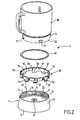
- the figure 2 illustrates the heating vessel 3 shown on the figure 1 .
- the heating vessel 3 comprises a base 10 and an annular side wall 20 of container removably mounted on the base 10.
- the base 10 has an annular portion 11 surrounding a heating base 12.
- the annular portion 11 is assembled with the heating base 12
- the base 10 may comprise a rotary working tool, not shown on the figure 2 .
- the heating base 12 has an axial opening 8.
- the annular portion 11 has an inner annular flange 13.
- the bottom heater 12 is connected to the inner annular collar 13.
- the annular portion 11 extends above the heating base 12.
- the annular portion 11 forms an upper annular wall 14 rising from the heating bottom 12.
- the upper annular wall 14 is peripheral.
- the annular portion 11 also extends below the heating bottom 12.
- the annular portion 11 forms a lower annular wall 15 extending below the heating bottom 12.
- the lower annular wall 15 is peripheral.
- Means 30 for holding the removable annular lateral container wall 20 are provided on the annular portion 11.
- the holding means 30 are designed to cooperate with an external face of the removable annular lateral container wall 20, as shown in FIG. figure 6 .
- the holding means 30 are arranged on the upper annular wall 14. More particularly, the holding means 30 comprise a locking ring 31 bayonet mounted movable relative to the upper annular wall 14.
- the locking ring 31 comprises lower legs 32 provided with external hooks 33 and the annular portion 11 has internal longitudinal slots 16 opening into an inner peripheral groove portion 17 of the upper annular wall 14.
- the locking ring 31 has internal longitudinal grooves 34 opening between two lower tabs 32 at a distance from one of said lower tabs.
- a lower edge 35 of the locking ring 31 adjacent to one of the internal longitudinal grooves 34 forms a retaining means for a lug 21 formed on the outer face of the lower portion of the removable annular side wall 20 container.
- a lateral face 36 of the lower lug adjacent to said lower edge 35 forms a lateral locking stop for said lug 21.
- the annular side wall advantageously comprises at least three lugs 21, and preferably four lugs 21, as shown in FIG. figure 2 .
- the annular portion 11 is advantageously made of plastic. According to a preferred embodiment illustrated on the Figures 3 to 6 and 9 , the part annular 11 comprises a piece overmolded around the heating bottom 12.
- the heating base 12 comprises a plate 50 associated with heating means 51.
- the heating means 51 are formed by a screen-printed heating element 52 arranged under the plate 50.
- One or more layers of dielectric insulation may be deposited between the plate 50 and the conductive tracks of the screen-printed heating element 52 and / or on the conductive tracks of the screen-printed heating element 52.
- the plate 50 is advantageously made of stainless steel, for example stainless steel type F17, 403 or 430.
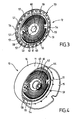
- the figure 3 illustrates the heating base 12 formed by the plate 50 carrying the screen-printed heating element 52.
- the screen-printed heating element 52 is made on the lower face of the plate 50.
- the plate 50 forms a disk.
- the thickness of the plate 50 is for example 1.2 mm, to facilitate the welding of a mass stud 53.
- the heating base 12 has a central portion 54 carrying the heating means 51 formed by the screen-printed heating element 52.
- the heating base 12 has a peripheral portion 55 advantageously comprising a raised edge 56 and cutouts 57.
- the raised edge 56 allows to improve the rigidity of said heating base 12.
- the cuts 57 make it easier to attach the annular portion 11 to the peripheral portion 55.
- the plate 50 advantageously has a swept area 58 between the central portion 54 and the peripheral portion 55 of the
- the resistive tracks of the screen-printed heating element 52 are surrounded by the embossed zone 58 and advantageously extend at a distance of at least 3 mm from the embossed zone 58.
- a central passage 59 is formed in the plate 50.
- the central passage 59 may advantageously have notches 60 as visible on the figure 3 and / or a raised edge. If desired the notches can be raised or not. The raised edge may be continuous or not.
- the resistive tracks of the serigraphed heating element 52 surround the central passage 59.
- the resistive tracks of the screen-printed heating element 52 are formed on an intermediate annular zone 61 of the heating base 12.
- the intermediate annular zone 61 surrounds a central zone 62 of the heating base 12 devoid of resistive tracks.
- the intermediate annular zone 61 is surrounded by a peripheral zone 63 of the heating base 12 also lacking resistive tracks.
- the intermediate annular zone 61 and the central zone 62 are formed on the central portion 54 of the heating base 12.
- the peripheral zone 63 extends on the periphery of the central portion 54 as well as on the embossed zone 58 and on the peripheral portion 55 .
- the figure 4 illustrates the base 10 after overmolding of the annular portion 11 around the heating base 12.
- the annular portion 11 is assembled with the peripheral portion 55 of the heating base 12.
- the annular portion 11 is made of material (s) adapted (s) to temperatures reached by the peripheral portion 55 of the heating base 12.
- the annular portion 11 may for example be made of glass filled polypropylene, in particular for the heating means 51 having a power of the order of 1000 W associated with the plate 50 made of stainless steel.
- the annular portion 11 may also be made of PBT, in particular for heating means 51 having a higher amount, up to 3000 W, associated with the plate 50 made of stainless steel.
- the annular portion 11 of the base 10 is overmolded around the central portion 54 of the heating base 12.
- the annular portion 11 is overmolded on the peripheral portion 55 around the embossed zone 58.
- the annular portion 11 is secured annularly with the peripheral portion 55 of the heating bottom 12.
- the peripheral zone 63 forms a thermal brake between the heating means 51 and the annular portion 11.
- the holding means 30 are formed inside the annular wall upper portion 14 of the annular portion 11, as visible on the figure 2 .
- the annular portion 11 forms an annular thermal brake made of a non-metallic material between the holding means 30 and the peripheral portion 55 of the heating base 12 and thus makes it possible to avoid the dispersion of the heat coming from the heating base 12 towards the annular side wall 20 removable container.
- a central core 64 is overmolded in the central zone 62 around the central passage 59.
- the notches 60 (visible on the figure 3 ) facilitate the attachment of the central core 64 to the central portion 54 of the heating base 12.
- the central zone 62 forms a thermal brake between the heating means 51 and the central core 64.
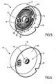
- the figure 5 illustrates the base 10 after mounting a connector 9 on the underside of the heating base 12.
- the connector 9 is arranged around the ground stud 53.
- the screen-printed heating element 52 advantageously has a saving at the central core 64.
- the heating base 12 is devoid of resistive tracks belonging to the screen-printed heating element 52.
- the central zone of the screen-printed heating element is usually one of the hottest areas.
- the resistive tracks of the screen-printed heating element 52 advantageously extend at a distance of at least 3 mm from the central core 64, for example at a distance of 10 mm.
- the figure 6 illustrates the base 10 after adding polymer material 65 to cover the underside of the plate 50 carrying the screen-printed heating element 52.
- FIGS 7 and 8 illustrate other annular side walls 24, 26 of container may be mounted on the base 10 in place of the annular side wall 20.
- the annular side walls 20, 24, 26 container are of different geometry.
- the annular side walls 20, 24, 26 of the container may also be made of different materials, for example example plastic, stainless steel, glass or even ceramic.
- the figure 9 illustrates a heating container 37 of household appliance for food preparation and / or drinks, comprising the base 10 illustrated on the Figures 1 to 6 and the annular annular container wall 26 illustrated on the figure 8 , mounted removably on said base 10 by means of the locking ring 31.
- the annular portion 11 forms an outer wall of the heating container 37.
- the annular side wall 26 of the container is mounted inside the annular portion 11.
- the heating base 12 has means 18 for receiving a rotary working tool 6.
- the receiving means 18 of the rotary working tool 6 comprise a driving element 19.
- the driving element 19 passes through the axial opening 8 of the heating bottom 12.
- the driving element 19 is mounted in the central core 64.
- the rotary working tool 6 can be fixed to the upper part of the driving element 19 or on the contrary be removable relative to the driving element 19, as shown in FIG. figure 9 .
- a seal 40 is interposed between the base 10 and a lower annular edge 22 of the annular side wall 20, 26 removable container.
- the seal 40 rests on the annular portion 11 at the periphery of the heating base 12.
- the seal 40 is placed in compression between the annular portion 11 and the lower annular edge 22 of the annular lateral wall 20, 26 of removable container by means of the crown In particular, the seal 40 rests on the inner annular flange 13.
- the seal 40 could in particular be overmoulded on the lower annular edge 22 of the removable annular side wall 20, 24, 26 of the container.
- the seal 40 is advantageously arranged at a distance from the heating means 51.
- the seal 40 is disposed at the periphery of the conductive tracks of the screen-printed heating element 52.
- the base 10 can be used with each of the annular side walls 20, 24, 26.
- the base 10 forms in particular a heating device 5 for the heating container 3 of the food and / or drink preparation appliance illustrated on the figure 1 , or for the heating vessel 37 illustrated on the figure 9 .
- the appliance for food and / or drink preparation illustrated on the figure 1 can receive a heating container formed by the base 10 and one of the annular side walls 20, 24, 26.
- the appliance for preparing food and / or drinks receiving the heating container 37 formed by the base 10 and the annular wall 26 represented on the figure 9 comprises a rotary working tool 6 disposed in the heating vessel 37, and a housing 7 having drive means for the rotary working tool 6, the housing 7 being formed by the base 1 shown in FIG. figure 1 .
- the annular side walls 20, 24, 26 and the base 10 form a set of accessories for household appliances for preparing food and / or drinks.
- the figure 10 illustrates a heating vessel 38 of a food and / or beverage preparation appliance, wherein the annular sidewall 26 shown in FIGS. figures 8 and 9 is mounted on a base 10 'having a central core 64' forming a chimney 8 '.
- the base 10 ' has an annular portion 11' surrounding a heating base 12 '.
- the annular portion 11 ' is identical to the annular portion 11 of the base 10.
- the annular portion 11' forms an outer wall of the heating vessel 38.
- the annular portion 11 ' is secured annularly with the peripheral portion 55' of the bottom heating element 12 'in a manner identical to the assembly of the annular portion 11 with the heating base 12 of the base 10.
- the heating base 12' is identical to the heating base 12 with the exception of the central core 64 'replacing the central core 64.
- the annular portion 11 ' forms an annular thermal brake made of non-metallic material between the holding means 30' and the peripheral portion 55 'of the heating base 12'.
- the base 10 ' has a connector 9'.
- the base 10 ' has means 18' for receiving a rotary working tool (not shown in FIG. figure 6 ).
- the receiving means 18 ' comprise a guiding member 19' provided for receiving said rotary working tool.
- the guide member 19 ' is formed by the chimney 8' rising from the heating bottom 12 '.
- Holding means 30 'of the removable annular side wall 26 of the container are provided on the annular portion 11'.
- the holding means 30 ' are disposed on the upper annular wall 14' of the annular portion 11 '.
- the holding means 30 ' comprise a locking ring 31' bayonet mounted movable relative to the upper annular wall 14 '.
- the annular side wall 26 of the container is mounted inside the annular portion 11 '.
- the base 10 ' can be used with each of the annular side walls 20, 24, 26.
- the base 10' forms in particular a heating device 5 'for the heating vessel 38 illustrated in FIG. figure 10 .
- the annular side walls 20, 24, 26 and the base 10 form a set of accessories for household appliances for preparing food and / or drinks.
- the appliance for food and / or drink preparation illustrated on the figure 11 comprises a base 101 forming a base 102 receiving a heating vessel 103 associated with a cover 104, and a housing 107 comprising means for driving a rotary working tool 106.
- the appliance for food and / or drink preparation illustrated on the figure 11 differs from the food and / or drink appliance shown on the display. figure 1 in that the housing 107 is formed by the cover 104.
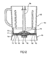
- the figure 12 illustrates the heating vessel 103 shown on the figure 11 receiving the rotary working tool 106.
- the heating container 103 has a base 110 and an annular side wall 120 of the container mounted on the base 110.
- the base 110 has an annular portion 111 surrounding a heating base 112.
- the annular portion 111 forms an outer wall of the heating vessel 103.
- the base 110 comprises a connector 109 advantageously arranged in the central position.
- the heating base 112 comprises a plate 150 carrying a screen-printed heating element 152.
- the plate 150 is advantageously identical to the plate 50.
- the screen-printed heating element 152 can easily have resistive tracks of different design and / or different power of the drawing and / or the power of the resistive tracks of the screen-printed heating element 52.
- Of the polymeric material 165 advantageously covers the bottom face of the heating base 112.
- the annular portion 111 is assembled with the peripheral portion 155 of the heating base 112 in an identical manner to the assembly of the annular portion 11 with the heating base 12 of the base 10.
- the annular portion 111 forms an annular thermal brake made of non-metallic material between the annular side wall 120 of the container and the peripheral portion 155 of the heating base 112.
- the base 110 is devoid of rotary working tool.
- the heating base 112 has receiving means 118 of the rotary working tool 106, visible on the figure 12 .
- the receiving means 118 of the rotary working tool 106 comprise a guide member 119. As shown in FIG. figure 12 , the guide member 119 is formed by an axis provided to receive the rotary working tool 106.
- the guide member 119 may be formed by a conformation formed on the upper face of the heating base 112, this conformation receiving a support element of the rotary working tool.
- said support member may be rotatably mounted relative to the main portion of the rotary working tool carrying the working member; said support member being immobilizable, in particular in rotation, relative to the base 110.
- the annular side wall 120 of the container is fixed to the annular portion 111, for example by gluing.
- a seal 140 is advantageously interposed between the base 110 and a lower annular edge 122 of the annular side wall 120 of the container.
- the position of the seal 140 is identical to the position of the seal 40. If desired the seal 140 may be overmolded on the lower annular edge 122 of the annular side wall 120 of the container.
- the figure 13 illustrates a heating vessel 203 receiving the rotary working tool 106 illustrated on the figure 12 .
- the heating vessel 203 may be used with the base 101, the lid 104, and the rotary work tool 106 of the food and / or beverage preparation appliance illustrated in FIG. figure 11 .
- the heating vessel 203 has a base 210 and an annular side wall 220 of container mounted on the base 210.
- the heating vessel 203 illustrated on the figure 13 differs from the heating vessel 103 illustrated on the figures 11 and 12 in that the annular side wall 220 of the container is removable.
- the base 210 forms a heating device 205 for the heating vessel 203 of the appliance for preparing food and / or drinks illustrated in FIG. figure 11 .
- the heating device 205 has an annular portion 211 surrounding a heating bottom 212.
- the annular portion 211 forms an outer wall of the heating vessel 203.
- the annular portion 211 is assembled with the peripheral portion 255 of the heating bottom 212 in a manner identical to the assembly of the annular portion 11 with the heating base 12 of the base 10.
- the heating base 212 is identical to the heating base 112 illustrated on the figure 12 .
- the annular portion 211 forms an annular thermal brake made of non-metallic material between the holding means 230 and the peripheral portion 255 of the heating bottom 212.
- the heating base 212 comprises a plate 250 carrying a screen-printed heating element 252.
- the plate 250 is advantageously identical to the plate 50.
- the screen-printed heating element 252 can easily have resistive tracks of different design and / or different power from the design and / or the power of the resistive tracks of the screen-printed heating element 52 and / or the screen-printed heating element 152.
- the heating base 212 comprises receiving means 218 of the rotary working tool 106.
- the receiving means 218 comprise a guide member 219.
- the polymer 265 advantageously covers the bottom face of the heating base 212.
- Retaining means 230 of the removable annular side wall 220 of the container are provided on the annular portion 111.
- the holding means 230 are arranged on the upper annular wall 214 rising from the heating bottom 212.
- the holding means 230 define a helical path for a screw connection with conformations 229 provided on the removable annular side wall 220 of the container.
- the annular removable side wall 220 of container is mounted inside the annular portion 211.
- a seal 240 is advantageously interposed between the base 210 and a lower annular edge 222 of the removable annular side wall 220 of the container.
- the position of the seal 240 is identical to the position of the seal 40.
- annular container side walls may be used with the base 210.
- the heating base 12; 12 '; 112; 212 and / or the annular portion 11; 11 '; 111; 211 and / or the annular side wall 20; 24; 26; 120; 220 container does not necessarily (not) have a circular geometry.
- the plate 50; 150; 250 is not necessarily made of stainless steel, but may in particular be made of aluminum or glass.
- the plate 50; 150; 250 may have a perforated periphery and / or cut, to facilitate the connection with the annular portion 11; 11 '; 111; 211.
- the power of the heating base 12; 12 ';112; 212 can be adapted to the envisaged uses, with for example a power of heating of the order of 500 W to 1200 W for a food processor type food preparation appliance having a rotary working tool, and up to 3000 W for a kettle type of beverage preparation apparatus usually without rotary working tool.
- the heating base 12; 12 ';112; 212 may have several power levels.
- the heating means 51 are not necessarily formed by a screen-printed heating element 52; 152; 252.
- the different means of receiving a rotary working tool can be combined with the different means of assembly between the base and the container side wall.
- the heating device or the heating container of an appliance for food preparation and / or drinks according to the invention may be devoid of reception means of a rotating work tool.
- the appliance for preparing food and / or drinks according to the invention can then, if desired, be devoid of a housing comprising means for driving a rotary working tool.
- the annular side wall 20; 24; 26; 120; 220 container is not necessarily mounted within the annular portion 11; 11 '; 111; 211.
- the annular portion 11; 11 ';111; 211 may in particular have a metal outer covering.
- at least the portion of the annular portion 11; 11 ';111; 211 connecting the holding means 30; 30'; 230 or the container 120 to the peripheral portion 55; 55 ';155; 255 of the heating bottom 12; 12 ';112; 212 is made of plastic.
Landscapes
- Engineering & Computer Science (AREA)
- Food Science & Technology (AREA)
- Mechanical Engineering (AREA)
- Cookers (AREA)
Description
- La présente invention concerne le domaine technique des appareils électroménagers de préparation d'aliments et/ou de boissons comportant un récipient associé à des moyens de chauffe.
- La présente invention concerne plus particulièrement un récipient chauffant et un dispositif chauffant pour un appareil du type précité.
- La présente invention concerne également un appareil électroménager de préparation d'aliments et/ou de boissons comportant un récipient chauffant.
- Il est connu des documents
US 3 220 450 ,DE 2 020 437 ,DE 3 507 276 ,DE 4 414 821 ,EP 0 963 726 ,EP 1 647 217 ,EP 1 733 664 de réaliser des appareils électroménagers de préparation d'aliments et/ou de boissons comportant un récipient associé à un siège chauffant ou à un socle chauffant. Une telle construction comporte l'inconvénient de présenter une inertie thermique importante, peu propice au pilotage précis de la température des aliments contenus dans le récipient. Une telle construction est également peu compatible avec l'utilisation de récipients différents dans un même appareil. - Il est connu des documents
EP 0 432 625 ,US 6 318 247 ,DE 1 02 26940 ,US 2005 045671 ,CN 1 586 378 de réaliser des appareils électroménagers de préparation d'aliments et/ou de boissons comportant un récipient présentant des moyens de chauffe solidaires du fond du récipient. Une telle construction comporte l'inconvénient de ne proposer qu'un seul type de récipient pour l'appareil. De plus les documentsEP 0 432 625 ,US 6 318 247 ,US 2005 045671 ,CN 1 586 378 proposent des moyens de chauffe de type élément chauffant blindé. De tels moyens de chauffe rendent difficiles la réalisation d'une chauffe précise et homogène. Le documentDE 1 02 26940 propose des moyens de chauffe de type élément chauffant sérigraphié. Toutefois la nature métallique du récipient rend plus difficile la réalisation d'une chauffe précise. - Il est connu du document
EP 1 733 664 de réaliser des appareils électroménagers de préparation d'aliments et/ou de boissons comportant des moyens de chauffe plongeant dans un récipient. Une telle construction comporte l'inconvénient de présenter des risques de surchauffe pour les aliments et/ou les boissons préparées, ainsi que des risques de brûlure pour l'utilisateur. - Un appareil selon le préambule de la revendication 1 est connu du document
DE 2 02 13 139 U . - Un but de la présente invention est de simplifier la réalisation d'un récipient chauffant ou d'un dispositif chauffant pour un récipient d'un appareil électroménager de préparation d'aliments et/ou de boissons.
- Un autre but de la présente invention est de proposer un récipient chauffant ou un dispositif chauffant pour un récipient d'un appareil électroménager de préparation d'aliments et/ou de boissons permettant de réaliser une chauffe plus efficace des aliments ou des boissons contenus dans le récipient de l'appareil.
- Un autre but de la présente invention est de proposer un récipient chauffant ou un dispositif chauffant pour un récipient d'un appareil électroménager de préparation d'aliments et/ou de boissons permettant de réaliser une variété plus grande de préparations culinaires.
- Un autre but de la présente invention est de proposer un récipient chauffant pour appareil électroménager de préparation d'aliments et/ou de boissons, comportant un dispositif chauffant du type précité.
- Un autre but de la présente invention est de proposer un appareil électroménager de préparation d'aliments et/ou de boissons présentant un récipient chauffant du type précité.
- Ces buts sont atteints avec un dispositif chauffant pour un récipient chauffant d'un appareil électroménager de préparation d'aliments et/ou de boissons, ledit dispositif chauffant comportant une partie annulaire solidarisée de manière annulaire avec une partie périphérique d'un fond chauffant, des moyens de maintien d'une paroi latérale annulaire amovible de récipient étant prévus sur ladite partie annulaire, du fait que ladite partie annulaire forme une paroi annulaire supérieure s'élevant à partir du fond chauffant. Cette disposition permet de simplifier l'assemblage de la paroi latérale annulaire amovible de récipient sur ladite partie annulaire. Ainsi la partie annulaire équipée de moyens de maintien d'une paroi latérale annulaire amovible de récipient constitue un élément intermédiaire entre ladite paroi latérale annulaire amovible de récipient et le fond chauffant. La partie annulaire fixée au fond chauffant permet de réaliser un accouplement mécanique avec la paroi latérale annulaire amovible de récipient. De plus la partie annulaire peut notamment en fonction des matériaux utilisés créer un frein thermique entre le fond chauffant et la paroi latérale annulaire amovible de récipient, ou au contraire assurer la diffusion des calories issues du fond chauffant vers la paroi latérale annulaire amovible de récipient. Ces dispositions permettent de réaliser un récipient chauffant d'appareil électroménager de préparation d'aliments et/ou de boissons présentant une configuration adaptée à la préparation à effectuer, tout en conservant une construction économique. En effet le dispositif chauffant proposé forme une embase de récipient pouvant être utilisée avec différentes parois latérales annulaires de forme et/ou de matières différentes. Ces dispositions permettent de réduire le coût de remise en état d'un récipient chauffant dont la paroi latérale annulaire est endommagée. Ces dispositions permettent également d'augmenter le nombre d'accessoires d'un appareil électroménager de préparation d'aliments et/ou de boissons chauffant, pour un coût peu élevé. Ces dispositions permettent également d'augmenter le nombre de versions d'appareils électroménagers de préparation d'aliments et/ou de boissons chauffants en conservant une construction standardisée pour la partie chauffante.
- Avantageusement alors la partie annulaire est dépourvue de structure métallique reliée à la partie périphérique du fond chauffant. Pour une meilleure précision de chauffe il n'est pas nécessaire que la partie annulaire accumule fortement les calories et/ou dissipe fortement les calories et/ou transmette fortement les calories issues du fond chauffant vers la paroi latérale annulaire amovible de récipient. De ce fait, la partie annulaire peut être réalisée en matériau peu conducteur de chaleur, présentant une capacité calorifique peu élevée. Ainsi ladite partie annulaire forme un frein thermique évitant la dissipation des calories issues du fond chauffant.
- Avantageusement alors au moins la portion de la partie annulaire reliant les moyens de maintien à la partie périphérique du fond chauffant est réalisée en matière plastique. Avantageusement alors, la partie annulaire est réalisée en matière plastique. En alternative, la partie annulaire peut notamment comporter une portion métallique telle qu'un habillage externe métallique.
- Selon une forme de réalisation avantageuse, la partie annulaire comporte une pièce surmoulée autour du fond chauffant. Cette construction permet de réaliser de manière économique un assemblage durable et étanche de la partie annulaire avec la partie périphérique du fond chauffant.
- Selon une forme de réalisation préférée le fond chauffant comporte une plaque portant un élément chauffant sérigraphié. Cette disposition permet de chauffer de manière plus uniforme le fond chauffant et de favoriser un pilotage plus précis de la température. Les éléments chauffants sérigraphiés présentent en outre l'avantage d'une faible émissivité par rayonnement.
- Avantageusement, la plaque est réalisée en matériau peu conducteur de chaleur, par exemple en acier inoxydable ou en verre, plutôt qu'en aluminium. Ainsi le chauffage produit par le fond chauffant s'effectue essentiellement par conduction au travers de la plaque. Les calories sont diffusées essentiellement à travers l'épaisseur de la plaque vers le contenu du récipient, et non transversalement dans la plaque vers la périphérie de la plaque, ce qui contribue à diminuer les températures rencontrées dans la partie annulaire. La portion de la partie annulaire reliant les moyens de maintien à la partie périphérique du fond chauffant réalisée en matière plastique contribue également à diminuer l'effet radiateur.
- Avantageusement, ladite partie annulaire s'étend en dessous du fond chauffant. Ainsi la partie annulaire peut servir de moyen d'appui. Avantageusement alors ladite partie annulaire forme une paroi annulaire inférieure s'étendant en dessous du fond chauffant.
- Avantageusement alors, les moyens de maintien sont disposés sur la paroi annulaire supérieure. Cette disposition permet de simplifier l'assemblage de la paroi latérale annulaire du récipient avec la partie annulaire. Cette disposition permet aussi de simplifier la construction du récipient.
- Alors, selon une forme de réalisation avantageuse, les moyens de maintien comportent une couronne de verrouillage par baïonnette montée mobile par rapport à la paroi annulaire supérieure. La paroi latérale annulaire du récipient peut ainsi être mise en place sans rotation par rapport au dispositif chauffant.
- Alors, selon une autre forme de réalisation avantageuse, les moyens de maintien définissent un chemin hélicoïdal. En d'autres termes, les moyens de maintien peuvent comporter des filetages ou des portions de filetages prévu(e)s pour coopérer avec des conformations adaptées de la paroi latérale annulaire du récipient.
- Selon une forme de réalisation, le fond chauffant présente des moyens de réception d'un outil de travail rotatif.
- Alors, selon un mode de réalisation, les moyens de réception d'un outil de travail rotatif comportent un élément d'entraînement. L'outil de travail rotatif peut être fixé à la partie supérieure de l'élément d'entraînement s'étendant au dessus du fond, ou au contraire être amovible par rapport à la partie supérieure de l'élément d'entraînement s'étendant au dessus du fond.
- Alors, selon un autre mode de réalisation, les moyens de réception d'un outil de travail rotatif comportent un organe de guidage. L'organe de guidage peut notamment former un axe recevant l'extrémité inférieure de l'outil de travail ou une conformation recevant un élément d'appui de l'outil de travail rotatif, cet élément d'appui pouvant être libre en rotation par rapport à une partie principale de l'outil de travail rotatif. L'entraînement de l'outil de travail rotatif peut être un entraînement supérieur ou un entraînement inférieur.
- Ces buts sont atteints également avec un récipient chauffant d'appareil électroménager de préparation d'aliments et/ou de boissons, comportant une embase et une paroi latérale annulaire de récipient montée amovible sur ladite embase, du fait que ladite embase forme un dispositif chauffant conforme à l'une au moins des caractéristiques précédentes. En d'autres termes, le dispositif chauffant est amovible par rapport à la paroi latérale de récipient.
- Si désiré un joint d'étanchéité peut être agencé entre la paroi latérale annulaire amovible de récipient et le dispositif chauffant. Le joint d'étanchéité peut notamment être interposé entre la paroi latérale annulaire amovible de récipient et le dispositif chauffant. En alternative, le joint d'étanchéité peut notamment être intégré à la partie inférieure de la paroi latérale annulaire amovible de récipient, par exemple par surmoulage. Avantageusement alors, le joint repose sur la partie annulaire en périphérie du fond chauffant. Cette disposition permet de diminuer l'échauffement du joint, et contribue à améliorer la durabilité du joint.
- Ces buts sont atteints également avec un récipient chauffant d'appareil électroménager de préparation d'aliments et/ou de boissons, du fait que ledit récipient chauffant présente une embase et une paroi latérale annulaire de récipient montée sur ladite embase, ladite embase comportant une partie annulaire solidarisée de manière annulaire avec une partie périphérique d'un fond chauffant, la paroi latérale annulaire de récipient étant fixée à la partie annulaire, ladite partie annulaire formant une paroi annulaire supérieure s'élevant à partir du fond chauffant. En d'autres termes, le dispositif chauffant est rendu solidaire et non démontable de la paroi latérale annulaire de récipient.
- Ainsi la partie annulaire est fixée d'une part à la paroi latérale annulaire de récipient et d'autre part au fond chauffant. La partie annulaire constitue un élément intermédiaire entre la paroi latérale annulaire de récipient et le fond chauffant. En fonction des matériaux utilisés la partie annulaire peut notamment créer un frein thermique entre le fond chauffant et la paroi latérale annulaire de récipient, ou au contraire assurer la diffusion des calories issues du fond chauffant vers la paroi latérale annulaire de récipient.
- Si désiré un joint d'étanchéité peut être agencé entre la paroi latérale annulaire de récipient et le dispositif chauffant. Le joint d'étanchéité peut notamment être interposé entre la paroi latérale annulaire de récipient et le dispositif chauffant. En alternative, le joint d'étanchéité peut notamment être intégré à la partie inférieure de la paroi latérale annulaire de récipient, par exemple par surmoulage. Avantageusement alors, le joint repose sur la partie annulaire en périphérie du fond chauffant. Cette disposition permet de diminuer l'échauffement du joint, et contribue à améliorer la durabilité du joint.
- Avantageusement alors la partie annulaire est dépourvue de structure métallique reliée à la partie périphérique du fond chauffant. Les moyens de chauffe sont associés au fond chauffant et non à la partie annulaire. Pour une meilleure précision de chauffe il n'est pas nécessaire que la partie annulaire accumule fortement les calories et/ou dissipe fortement les calories et/ou transmette fortement les calories vers la paroi latérale annulaire de récipient. De ce fait, la partie annulaire peut être réalisée en matériau peu conducteur de chaleur, présentant une capacité calorifique peu élevée. Ainsi ladite partie annulaire forme un frein thermique évitant la dissipation des calories issues du fond chauffant.
- Avantageusement alors au moins la portion de la partie annulaire reliant la paroi latérale annulaire de récipient à la partie périphérique du fond chauffant est réalisée en matière plastique. Avantageusement alors, la partie annulaire est réalisée en matière plastique. En alternative, la partie annulaire peut notamment comporter une portion métallique telle qu'un habillage externe métallique.
- Selon une forme de réalisation avantageuse, la partie annulaire comporte une pièce surmoulée autour du fond chauffant. Cette construction permet de réaliser de manière économique un assemblage durable et étanche de la partie annulaire avec la partie périphérique du fond chauffant.
- Selon une forme de réalisation préférée le fond chauffant comporte une plaque portant un élément chauffant sérigraphié. Cette disposition permet de chauffer de manière plus uniforme le fond chauffant et de favoriser un pilotage plus précis de la température. Les éléments chauffants sérigraphiés présentent en outre l'avantage d'une faible émissivité par rayonnement.
- Avantageusement, la plaque est réalisée en matériau peu conducteur de chaleur, par exemple en acier inoxydable ou en verre, plutôt qu'en aluminium. Ainsi le chauffage produit par le fond chauffant s'effectue essentiellement par conduction au travers de la plaque. Les calories sont diffusées essentiellement à travers l'épaisseur de la plaque vers le contenu du récipient, et non transversalement dans la plaque vers la périphérie de la plaque, ce qui contribue à diminuer les températures rencontrées dans la partie annulaire. La portion de la partie annulaire reliant les moyens de maintien à la partie périphérique du fond chauffant réalisée en matière plastique contribue également à diminuer l'effet radiateur.
- Avantageusement, ladite partie annulaire s'étend en dessous du fond chauffant. Ainsi la partie annulaire peut servir de moyen d'appui. Avantageusement alors ladite partie annulaire forme une paroi annulaire inférieure s'étendant en dessous du fond chauffant.
- Avantageusement encore, ladite partie annulaire forme une paroi annulaire supérieure s'élevant à partir du fond chauffant. Cette disposition permet de simplifier l'assemblage de la paroi latérale annulaire amovible de récipient sur ladite partie annulaire.
- Selon une forme de réalisation, le fond chauffant présente des moyens de réception d'un outil de travail rotatif.
- Alors, selon un mode de réalisation, les moyens de réception d'un outil de travail rotatif comportent un élément d'entraînement. L'outil de travail rotatif peut être fixé à la partie supérieure de l'élément d'entraînement s'étendant au dessus du fond, ou au contraire être amovible par rapport à la partie supérieure de l'élément d'entraînement s'étendant au dessus du fond.
- Alors, selon un autre mode de réalisation, les moyens de réception d'un outil de travail rotatif comportent un organe de guidage. L'organe de guidage peut notamment former un axe recevant l'extrémité inférieure de l'outil de travail ou une conformation recevant un élément d'appui de l'outil de travail rotatif, cet élément d'appui pouvant être libre en rotation par rapport à une partie principale de l'outil de travail rotatif. L'entraînement de l'outil de travail rotatif peut être un entraînement supérieur ou un entraînement inférieur.
- Ces buts sont atteints également avec un appareil électroménager de préparation d'aliments et/ou de boissons comprenant un récipient chauffant selon l'une au moins des caractéristiques précédentes.
- Ces buts sont atteints également avec un ensemble d'accessoires d'appareil électroménager de préparation d'aliments et/ou de boissons, comportant une embase et au moins deux parois latérales annulaires de récipient susceptibles d'être montées sur ladite embase, du fait que ladite embase forme un dispositif chauffant conforme à l'une au moins des caractéristiques précédentes.
- Si désiré un joint d'étanchéité peut être agencé entre la paroi latérale annulaire amovible de récipient et le dispositif chauffant. Le joint d'étanchéité peut notamment être interposé entre la paroi latérale annulaire amovible de récipient et le dispositif chauffant. En alternative, le joint d'étanchéité peut notamment être intégré à la partie inférieure de la paroi latérale annulaire amovible de récipient, par exemple par surmoulage. Avantageusement alors, le joint repose sur la partie annulaire en périphérie du fond chauffant. Cette disposition permet de diminuer l'échauffement du joint, et contribue à améliorer la durabilité du joint.
- Avantageusement encore, ledit ensemble d'accessoires d'appareil électroménager de préparation d'aliments et/ou de boissons comporte deux parois latérales annulaires de récipient de géométries différentes. Cette disposition permet d'obtenir des récipients mieux adaptés aux préparations à réaliser.
- Avantageusement encore, ledit ensemble d'accessoires d'appareil électroménager de préparation d'aliments et/ou de boissons comporte deux parois latérales annulaires de récipient réalisées dans des matières différentes. Cette disposition permet aussi d'obtenir des récipients mieux adaptés aux préparations à réaliser.
- Ces buts sont atteints également avec un appareil électroménager de préparation d'aliments et/ou de boissons comprenant un récipient chauffant réalisé à partir d'un ensemble d'accessoires d'appareil électroménager de préparation d'aliments et/ou de boissons selon l'une des caractéristiques précédentes.
- Selon une forme de réalisation, ledit appareil électroménager de préparation d'aliments et/ou de boissons comprend un outil de travail rotatif disposé dans ledit récipient chauffant, et un boîtier comportant des moyens d'entraînement de l'outil de travail rotatif. Le récipient chauffant peut notamment être disposé sur le boîtier ou sous le boîtier.
- L'invention sera mieux comprise à l'étude de deux exemples de réalisation et de deux variantes, pris à titre nullement limitatif, illustrés dans les figures annexées, dans lesquelles :
- la
figure 1 est une vue en perspective d'un premier exemple de réalisation d'un appareil électroménager de préparation d'aliments et/ou de boissons comprenant un récipient chauffant comportant un dispositif chauffant selon l'invention, - la
figure 2 est une vue en perspective et en éclaté du récipient chauffant illustré sur lafigure 1 , montrant mieux le dispositif chauffant, - la
figure 3 est une vue en perspective d'un fond chauffant appartenant au dispositif chauffant illustré sur lesfigures 1 et2 , - la
figure 4 est une vue du dispositif chauffant illustré sur lesfigures 1 et2 après surmoulage d'une partie annulaire et d'un noyau central sur le fond chauffant illustré sur lafigure 3 , - la
figure 5 est une vue du dispositif chauffant illustré sur lesfigures 1 et2 , après ajout d'un connecteur sur le fond chauffant tel qu'illustré sur lafigure 4 , - la
figure 6 est une vue du dispositif chauffant illustré sur lesfigures 1 et2 , après ajout de matériau polymère pour recouvrir le fond chauffant tel qu'illustré sur lafigure 5 , - la
figure 7 est une vue en perspective d'un élément de récipient adapté pour une utilisation avec le dispositif chauffant illustré sur lafigure 6 , - la
figure 8 est une vue en perspective d'un autre élément de récipient adapté pour une utilisation avec le dispositif chauffant illustré sur lafigure 6 , - la
figure 9 est une vue en coupe de l'élément de récipient illustré sur lafigure 8 , assemblé avec le dispositif chauffant illustré sur lafigure 6 , - la
figure 10 est une vue en coupe de l'élément de récipient illustré sur lafigure 8 , assemblé sur une variante de réalisation du dispositif de chauffant illustré sur lafigure 6 , - la
figure 11 est une vue en perspective et en éclaté d'un deuxième exemple de réalisation d'un appareil électroménager de préparation d'aliments et/ou de boissons comprenant un récipient chauffant comportant un dispositif chauffant selon l'invention, - la
figure 12 est une vue en coupe du récipient chauffant illustré sur lafigure 11 , montrant mieux le dispositif chauffant, - la
figure 13 est une vue en coupe d'une variante de réalisation du récipient chauffant illustré sur lesfigures 11 et12 , comportant un dispositif chauffant selon l'invention. - L'appareil électroménager de préparation d'aliments et/ou de boissons illustré sur la
figure 1 comporte une base 1 formant un socle 2 recevant un récipient chauffant 3. Le récipient chauffant 3 est associé à un couvercle 4. - La
figure 2 illustre le récipient chauffant 3 montré sur lafigure 1 . Le récipient chauffant 3 comporte une embase 10 et une paroi latérale annulaire 20 de récipient montée amovible sur l'embase 10. L'embase 10 comporte une partie annulaire 11 entourant un fond chauffant 12. La partie annulaire 11 est assemblée avec le fond chauffant 12. L'embase 10 peut comporter un outil de travail rotatif, non représenté sur lafigure 2 . A cet effet le fond chauffant 12 présente une ouverture axiale 8. - La partie annulaire 11 comporte une collerette annulaire interne 13. Le fond chauffant 12 est relié à la collerette annulaire interne 13.
- La partie annulaire 11 s'étend au dessus du fond chauffant 12. La partie annulaire 11 forme une paroi annulaire supérieure 14 s'élevant à partir du fond chauffant 12. La paroi annulaire supérieure 14 est périphérique.
- La partie annulaire 11 s'étend aussi en dessous du fond chauffant 12. La partie annulaire 11 forme une paroi annulaire inférieure 15 s'étendant en dessous du fond chauffant 12. La paroi annulaire inférieure 15 est périphérique.
- Des moyens de maintien 30 de la paroi latérale annulaire 20 amovible de récipient sont prévus sur la partie annulaire 11. Les moyens de maintien 30 sont prévus pour coopérer avec une face externe de la paroi latérale annulaire 20 amovible de récipient, tel que représenté sur la
figure 6 . - Les moyens de maintien 30 sont disposés sur la paroi annulaire supérieure 14. Plus particulièrement, les moyens de maintien 30 comportent une couronne de verrouillage 31 à baïonnette montée mobile par rapport à la paroi annulaire supérieure 14. A cet effet la couronne de verrouillage 31 comporte des pattes inférieures 32 munies de crochets externes 33 et la partie annulaire 11 présente des encoches longitudinales internes 16 débouchant dans une portion de rainure périphérique interne 17 de la paroi annulaire supérieure 14. La couronne de verrouillage 31 comporte des rainures longitudinales internes 34 débouchant entre deux pattes inférieures 32 à distance de l'une desdites pattes inférieures. Ainsi un bord inférieur 35 de la couronne de verrouillage 31 adjacent à l'une des rainures longitudinales internes 34 forme un moyen de retenue pour un ergot 21 ménagé sur la face externe de la partie inférieure de la paroi latérale annulaire 20 amovible de récipient. Une face latérale 36 de la patte inférieure adjacente audit bord inférieur 35 forme une butée latérale de verrouillage pour ledit ergot 21. La paroi latérale annulaire 20 comporte avantageusement au moins trois ergots 21, et de préférence quatre ergots 21, tel que représenté sur la
figure 2 . - La partie annulaire 11 est avantageusement réalisée en matière plastique. Selon un mode de réalisation préféré illustré sur les
figures 3 à 6 et9 , la partie annulaire 11 comporte une pièce surmoulée autour du fond chauffant 12. - Tel que mieux visible sur les
figures 3 à 6 , le fond chauffant 12 comporte une plaque 50 associée à des moyens de chauffe 51. Selon la forme de réalisation préférée visible sur lesfigures 3 à 5 , les moyens de chauffe 51 sont formés par un élément chauffant sérigraphié 52 disposé sous la plaque 50. - Une ou plusieurs couches d'isolant diélectrique peuvent être déposées entre la plaque 50 et les pistes conductrices de l'élément chauffant sérigraphié 52 et/ou sur les pistes conductrices de l'élément chauffant sérigraphié 52.
- Selon la forme de réalisation préférée visible sur les
figures 3 à 5 , la plaque 50 est avantageusement réalisée en acier inoxydable, par exemple en acier inoxydable de type F17, 403 ou 430. - La
figure 3 illustre le fond chauffant 12 formé par la plaque 50 portant l'élément chauffant sérigraphié 52. L'élément chauffant sérigraphié 52 est réalisé sur la face inférieure de la plaque 50. La plaque 50 forme un disque. L'épaisseur de la plaque 50 est par exemple de 1,2 mm, pour faciliter la soudure d'un goujon de masse 53. - Le fond chauffant 12 présente une partie centrale 54 portant les moyens de chauffe 51 formés par l'élément chauffant sérigraphié 52. Le fond chauffant 12 présente une partie périphérique 55 comportant avantageusement un bord 56 relevé ainsi que des découpes 57. Le bord 56 relevé permet d'améliorer la rigidité dudit fond chauffant 12. Les découpes 57 permettent de faciliter l'accrochage de la partie annulaire 11 sur la partie périphérique 55. La plaque 50 présente avantageusement une zone emboutie 58 entre la partie centrale 54 et la partie périphérique 55 du fond chauffant 12. Les pistes résistives de l'élément chauffant sérigraphié 52 sont entourées par la zone emboutie 58 et s'étendent avantageusement à une distance d'au moins 3 mm de la zone emboutie 58.
- Un passage central 59 est ménagé dans la plaque 50. Le passage central 59 peut présenter avantageusement des encoches 60 tel que visibles sur la
figure 3 et/ou un bord relevé. Si désiré les encoches peuvent être relevées ou non. Le bord relevé peut être continu ou non. Les pistes résistives de l'élément chauffant sérigraphié 52 entourent le passage central 59. - Les pistes résistives de l'élément chauffant sérigraphié 52 sont ménagées sur une zone annulaire intermédiaire 61 du fond chauffant 12. La zone annulaire intermédiaire 61 entoure une zone centrale 62 du fond chauffant 12 dépourvue de pistes résistives. La zone annulaire intermédiaire 61 est entourée par une zone périphérique 63 du fond chauffant 12 également dépourvue de pistes résistives. La zone annulaire intermédiaire 61 et la zone centrale 62 sont ménagées sur la partie centrale 54 du fond chauffant 12. La zone périphérique 63 s'étend sur la périphérie de la partie centrale 54 ainsi que sur la zone emboutie 58 et sur la partie périphérique 55.
- La
figure 4 illustre l'embase 10 après surmoulage de la partie annulaire 11 autour du fond chauffant 12. La partie annulaire 11 est assemblée avec la partie périphérique 55 du fond chauffant 12. La partie annulaire 11 est réalisée en matériau(x) adapté(s) aux températures atteintes par la partie périphérique 55 du fond chauffant 12. La partie annulaire 11 peut par exemple être réalisée en polypropylène chargé verre, notamment pour les moyens de chauffe 51 présentant une puissance de l'ordre de 1000 W associés à la plaque 50 réalisée en acier inoxydable. La partie annulaire 11 peut aussi être réalisée en PBT, notamment pour des moyens de chauffe 51 présentant plus élevée, jusqu'à 3000 W, associés à la plaque 50 réalisée en acier inoxydable. La partie annulaire 11 de l'embase 10 est surmoulée autour de la partie centrale 54 du fond chauffant 12. - Plus particulièrement, la partie annulaire 11 est surmoulée sur la partie périphérique 55 autour de la zone emboutie 58. Ainsi la partie annulaire 11 est solidarisée de manière annulaire avec la partie périphérique 55 du fond chauffant 12. La zone périphérique 63 forme un frein thermique entre les moyens de chauffe 51 et la partie annulaire 11.
- Les moyens de maintien 30 sont ménagés à l'intérieur de la paroi annulaire supérieure 14 de la partie annulaire 11, tel que visible sur la
figure 2 . La partie annulaire 11 forme un frein thermique annulaire réalisé en matériau non métallique entre les moyens de maintien 30 et la partie périphérique 55 du fond chauffant 12 et permet ainsi d'éviter la dispersion des calories issues du fond chauffant 12 vers la paroi latérale annulaire 20 amovible de récipient. - Un noyau central 64 est surmoulé dans la zone centrale 62 autour du passage central 59. Les encoches 60 (visibles sur la
figure 3 ) facilitent l'accrochage du noyau central 64 à la partie centrale 54 du fond chauffant 12. La zone centrale 62 forme un frein thermique entre les moyens de chauffe 51 et le noyau central 64. - La
figure 5 illustre l'embase 10 après montage d'un connecteur 9 sur la face inférieure du fond chauffant 12. Le connecteur 9 est agencé autour du goujon de masse 53. - Tel que bien visible sur les
figures 3 à 5 , l'élément chauffant sérigraphié 52 présente avantageusement une épargne au niveau du noyau central 64. En d'autres termes, au niveau du noyau central 64 le fond chauffant 12 est dépourvu de pistes résistives appartenant à l'élément chauffant sérigraphié 52. En effet, en l'absence d'une telle épargne la zone centrale de l'élément chauffant sérigraphié est usuellement l'une des zones les plus chaudes. Les pistes résistives de l'élément chauffant sérigraphié 52 s'étendent avantageusement à une distance d'au moins 3 mm du noyau central 64, par exemple à une distance de 10 mm. - La
figure 6 illustre l'embase 10 après ajout de matériau polymère 65 pour recouvrir la face inférieure de la plaque 50 portant l'élément chauffant sérigraphié 52. - Les
figures 7 et 8 illustrent d'autres parois latérales annulaires 24, 26 de récipient susceptibles d'être montées sur l'embase 10 à la place de la paroi latérale annulaire 20. Les parois latérales annulaires 20, 24, 26 de récipient sont de géométrie différentes. Les parois latérales annulaires 20, 24, 26 de récipient peuvent aussi être réalisées dans des matières différentes, par exemple en matière plastique, en acier inoxydable, en verre, voire en céramique. - La
figure 9 illustre un récipient chauffant 37 d'appareil électroménager de préparation d'aliments et/ou de boissons, comportant l'embase 10 illustrée sur lesfigures 1 à 6 et la paroi latérale annulaire 26 de récipient illustrée sur lafigure 8 , montée amovible sur ladite embase 10 au moyen de la couronne de verrouillage 31. La partie annulaire 11 forme une paroi externe du récipient chauffant 37. La paroi latérale annulaire 26 de récipient est montée à l'intérieur de la partie annulaire 11. - Le fond chauffant 12 présente des moyens de réception 18 d'un outil de travail rotatif 6. Les moyens de réception 18 de l'outil de travail rotatif 6 comportent un élément d'entraînement 19. L'élément d'entraînement 19 traverse l'ouverture axiale 8 du fond chauffant 12. L'élément d'entraînement 19 est monté dans le noyau central 64. L'outil de travail rotatif 6 peut être fixé à la partie supérieure de l'élément d'entraînement 19 ou au contraire être amovible par rapport à l'élément d'entraînement 19, tel que représenté sur la
figure 9 . - Selon la réalisation illustrée sur les
figures 1 ,2 et9 , un joint 40 est interposé entre l'embase 10 et un bord annulaire inférieur 22 de la paroi latérale annulaire 20, 26 amovible de récipient. Le joint 40 repose sur la partie annulaire 11 en périphérie du fond chauffant 12. Le joint 40 est mis en compression entre la partie annulaire 11 et le bord annulaire inférieur 22 de la paroi latérale annulaire 20, 26 amovible de récipient au moyen de la couronne de verrouillage 31. Plus particulièrement, le joint 40 repose sur la collerette annulaire interne 13. En alternative le joint 40 pourrait notamment être surmoulé sur le bord annulaire inférieur 22 de la paroi latérale annulaire 20, 24, 26 amovible de récipient. Le joint 40 est avantageusement disposé à distance des moyens de chauffe 51. A cet effet le joint 40 est disposé en périphérie des pistes conductrices de l'élément chauffant sérigraphié 52. - L'embase 10 peut être utilisée avec chacune des parois latérales annulaires 20, 24, 26. Ainsi l'embase 10 forme notamment un dispositif chauffant 5 pour le récipient chauffant 3 de l'appareil électroménager de préparation d'aliments et/ou de boissons illustré sur la
figure 1 , ou pour le récipient chauffant 37 illustré sur lafigure 9 . - L'appareil électroménager de préparation d'aliments et/ou de boissons illustré sur la
figure 1 peut recevoir un récipient chauffant formé par l'embase 10 et l'une des parois latérales annulaires 20, 24, 26. - L'appareil électroménager de préparation d'aliments et/ou de boissons recevant le récipient chauffant 37 formé par l'embase 10 et la paroi annulaire 26 représentées sur la
figure 9 comporte un outil de travail rotatif 6 disposé dans le récipient chauffant 37, et un boîtier 7 comportant des moyens d'entraînement de l'outil de travail rotatif 6, le boîtier 7 étant formé par la base 1 représentée sur lafigure 1 . - Les parois latérales annulaires 20, 24, 26 et l'embase 10 forment un ensemble d'accessoires d'appareil électroménager de préparation d'aliments et/ou de boissons.
- La
figure 10 illustre un récipient chauffant 38 d'appareil électroménager de préparation d'aliments et/ou de boissons, dans lequel la paroi latérale annulaire 26 illustrée sur lesfigures 8 et9 est montée sur une embase 10' présentant un noyau central 64' formant une cheminée 8'. - L'embase 10' comporte une partie annulaire 11' entourant un fond chauffant 12'. La partie annulaire 11' est identique à la partie annulaire 11 de l'embase 10. La partie annulaire 11' forme une paroi externe du récipient chauffant 38. La partie annulaire 11' est solidarisée de manière annulaire avec la partie périphérique 55' du fond chauffant 12' de manière identique à l'assemblage de la partie annulaire 11 avec le fond chauffant 12 de l'embase 10. Le fond chauffant 12' est identique au fond chauffant 12 à l'exception du noyau central 64' remplaçant le noyau central 64. La partie annulaire 11' forme un frein thermique annulaire réalisé en matériau non métallique entre les moyens de maintien 30' et la partie périphérique 55' du fond chauffant 12'. L'embase 10' comporte un connecteur 9'. Du matériau polymère 65' recouvre avantageusement la face inférieure du fond chauffant 12'. L'embase 10' présente des moyens de réception 18' d'un outil de travail rotatif (non représenté sur la
figure 6 ). Les moyens de réception 18' comportent un organe de guidage 19' prévu pour recevoir ledit outil de travail rotatif. L'organe de guidage 19' est formé par la cheminée 8' s'élevant du fond chauffant 12'. - Des moyens de maintien 30' de la paroi latérale annulaire 26 amovible de récipient sont prévus sur la partie annulaire 11'. Les moyens de maintien 30' sont disposés sur la paroi annulaire supérieure 14' de la partie annulaire 11'. Les moyens de maintien 30' comportent une couronne de verrouillage 31' à baïonnette montée mobile par rapport à la paroi annulaire supérieure 14'. La paroi latérale annulaire 26 de récipient est montée à l'intérieur de la partie annulaire 11'.
- L'embase 10' peut être utilisée avec chacune des parois latérales annulaires 20, 24, 26. Ainsi l'embase 10' forme notamment un dispositif chauffant 5' pour le récipient chauffant 38 illustré sur la
figure 10 . - Les parois latérales annulaires 20, 24, 26 et l'embase 10' forment un ensemble d'accessoires d'appareil électroménager de préparation d'aliments et/ou de boissons.
- L'appareil électroménager de préparation d'aliments et/ou de boissons illustré sur la
figure 11 comporte une base 101 formant un socle 102 recevant un récipient chauffant 103 associé à un couvercle 104, ainsi qu'un boîtier 107 comportant des moyens d'entraînement d'un outil de travail rotatif 106. - L'appareil électroménager de préparation d'aliments et/ou de boissons illustré sur la
figure 11 diffère de l'appareil électroménager de préparation d'aliments et/ou de boissons illustré sur lafigure 1 en ce que le boîtier 107 est formé par le couvercle 104. - La
figure 12 illustre le récipient chauffant 103 montré sur lafigure 11 , recevant l'outil de travail rotatif 106. Le récipient chauffant 103 présente une embase 110 et une paroi latérale annulaire 120 de récipient montée sur l'embase 110. - L'embase 110 comporte une partie annulaire 111 entourant un fond chauffant 112. La partie annulaire 111 forme une paroi externe du récipient chauffant 103. L'embase 110 comporte un connecteur 109 avantageusement agencé en position centrale. Le fond chauffant 112 comporte une plaque 150 portant un élément chauffant sérigraphié 152. La plaque 150 est avantageusement identique à la plaque 50. L'élément chauffant sérigraphié 152 peut aisément présenter des pistes résistives de dessin différent et/ou de puissance différente du dessin et/ou de la puissance des pistes résistives de l'élément chauffant sérigraphié 52. Du matériau polymère 165 recouvre avantageusement la face inférieure du fond chauffant 112. La partie annulaire 111 est assemblée avec la partie périphérique 155 du fond chauffant 112 de manière identique à l'assemblage de la partie annulaire 11 avec le fond chauffant 12 de l'embase 10. La partie annulaire 111 forme un frein thermique annulaire réalisé en matériau non métallique entre la paroi latérale annulaire 120 de récipient et la partie périphérique 155 du fond chauffant 112. La paroi latérale annulaire 120 de récipient est montée à l'intérieur de la partie annulaire 111.
- L'embase 110 est dépourvue d'outil de travail rotatif. Le fond chauffant 112 présente des moyens de réception 118 de l'outil de travail rotatif 106, visibles sur la
figure 12 . Les moyens de réception 118 de l'outil de travail rotatif 106 comportent un organe de guidage 119. Tel que représenté sur lafigure 12 , l'organe de guidage 119 est formé par un axe prévu pour recevoir l'outil de travail rotatif 106. - A titre de variante, non représentée aux figures, l'organe de guidage 119 peut être formé par une conformation ménagée sur la face supérieure du fond chauffant 112, cette conformation recevant un élément d'appui de l'outil de travail rotatif. Si désiré, ledit élément d'appui peut être monté rotatif par rapport à la partie principale de l'outil de travail rotatif portant l'organe de travail ; ledit élément d'appui pouvant être immobilisé, notamment en rotation, par rapport à l'embase 110.
- La paroi latérale annulaire 120 de récipient est fixée à la partie annulaire 111, par exemple par collage. Un joint 140 est avantageusement interposé entre l'embase 110 et un bord annulaire inférieur 122 de la paroi latérale annulaire 120 de récipient. La position du joint 140 est identique à la position du joint 40. Si désiré le joint 140 peut être surmoulé sur le bord annulaire inférieur 122 de la paroi latérale annulaire 120 de récipient.
- La
figure 13 illustre un récipient chauffant 203 recevant l'outil de travail rotatif 106 illustré sur lafigure 12 . Le récipient chauffant 203 peut être utilisé avec la base 101, le couvercle 104 et l'outil de travail rotatif 106 de l'appareil électroménager de préparation d'aliments et/ou de boissons illustré sur lafigure 11 . Le récipient chauffant 203 comporte une embase 210 et une paroi latérale annulaire 220 de récipient montée sur l'embase 210. - Le récipient chauffant 203 illustré sur la
figure 13 diffère du récipient chauffant 103 illustré sur lesfigures 11 et12 en ce que la paroi latérale annulaire 220 de récipient est amovible. Ainsi l'embase 210 forme un dispositif chauffant 205 pour le récipient chauffant 203 de l'appareil électroménager de préparation d'aliments et/ou de boissons illustré sur lafigure 11 . - Le dispositif chauffant 205 comporte une partie annulaire 211 entourant un fond chauffant 212. La partie annulaire 211 forme une paroi externe du récipient chauffant 203. La partie annulaire 211 est assemblée avec la partie périphérique 255 du fond chauffant 212 de manière identique à l'assemblage de la partie annulaire 11 avec le fond chauffant 12 de l'embase 10. Le fond chauffant 212 est identique au fond chauffant 112 illustré sur la
figure 12 . La partie annulaire 211 forme un frein thermique annulaire réalisé en matériau non métallique entre les moyens de maintien 230 et la partie périphérique 255 du fond chauffant 212. Le fond chauffant 212 comporte une plaque 250 portant un élément chauffant sérigraphié 252. La plaque 250 est avantageusement identique à la plaque 50. L'élément chauffant sérigraphié 252 peut aisément présenter des pistes résistives de dessin différent et/ou de puissance différente du dessin et/ou de la puissance des pistes résistives de l'élément chauffant sérigraphié 52 et/ou de l'élément chauffant sérigraphié 152. Le fond chauffant 212 comporte des moyens de réception 218 de l'outil de travail rotatif 106. Les moyens de réception 218 comportent un organe de guidage 219. Du matériau polymère 265 recouvre avantageusement la face inférieure du fond chauffant 212. - Des moyens de maintien 230 de la paroi latérale annulaire 220 amovible de récipient sont prévus sur la partie annulaire 111. Les moyens de maintien 230 sont disposés sur la paroi annulaire supérieure 214 s'élevant à partir du fond chauffant 212. Les moyens de maintien 230 définissent un chemin hélicoïdal pour un assemblage par vissage avec des conformations 229 ménagées sur la paroi latérale annulaire 220 amovible de récipient. La paroi latérale annulaire 220 amovible de récipient est montée à l'intérieur de la partie annulaire 211.
- Un joint 240 est avantageusement interposé entre l'embase 210 et un bord annulaire inférieur 222 de la paroi latérale annulaire 220 amovible de récipient. La position du joint 240 est identique à la position du joint 40.
- Si désiré d'autres parois latérales annulaires de récipient (non représentées aux figures) peuvent être utilisées avec l'embase 210.
- A titre de variante complémentaire pour les différents exemples de réalisation et leurs variantes, le fond chauffant 12 ; 12' ; 112 ; 212 et/ou la partie annulaire 11 ; 11' ; 111 ; 211 et/ou la paroi latérale annulaire 20 ; 24 ; 26 ; 120 ; 220 de récipient ne présente(nt) pas nécessairement une géométrie circulaire.
- A titre de variante complémentaire pour les différents exemples de réalisation et leurs variantes, la plaque 50 ; 150 ; 250 n'est pas nécessairement réalisée en acier inoxydable, mais peut notamment être réalisée en aluminium ou en verre.
- A titre de variante complémentaire pour les différents exemples de réalisation et leurs variantes, la plaque 50 ; 150 ; 250 peut présenter une périphérie ajourée et/ou découpée, pour faciliter la liaison avec la partie annulaire 11 ; 11';111;211.
- A titre de variante complémentaire pour les différents exemples de réalisation et leurs variantes, la puissance du fond chauffant 12 ; 12' ; 112 ; 212 peut être adaptée aux utilisations envisagées, avec par exemple une puissance de chauffe de l'ordre de 500 W à 1200 W pour un appareil électroménager de préparation d'aliments de type robot de préparation culinaire comportant un outil de travail rotatif, et jusqu'à 3000 W pour un appareil électroménager de préparation de boissons de type bouilloire usuellement dépourvu d'outil de travail rotatif. Si désiré le fond chauffant 12 ; 12' ; 112 ; 212 peut comporter plusieurs niveaux de puissance.
- A titre de variante complémentaire pour les différents exemples de réalisation et leurs variantes, les moyens de chauffe 51 ne sont pas nécessairement formés par un élément chauffant sérigraphié 52 ; 152 ; 252.
- A titre de variante complémentaire pour les différents exemples de réalisation et leurs variantes, les différents moyens de réception d'un outil de travail rotatif peuvent être combinés indifféremment avec les différents moyens d'assemblage entre embase et paroi latérale de récipient.
- A titre de variante complémentaire pour les différents exemples de réalisation et leurs variantes, le dispositif chauffant ou le récipient chauffant d'un appareil électroménager de préparation d'aliments et/ou de boissons selon l'invention peut être dépourvu de moyens de réception d'un outil de travail rotatif. L'appareil électroménager de préparation d'aliments et/ou de boissons selon l'invention peut alors si désiré être dépourvu de boîtier comportant des moyens d'entraînement d'un outil de travail rotatif.
- A titre de variante complémentaire pour les différents exemples de réalisation et leurs variantes, la paroi latérale annulaire 20 ; 24 ; 26 ; 120 ; 220 de récipient n'est pas nécessairement montée à l'intérieur de la partie annulaire 11 ; 11' ; 111 ; 211.
- A titre de variante complémentaire pour les différents exemples de réalisation et leurs variantes, la partie annulaire 11 ; 11'; 111 ; 211 peut notamment présenter un habillage extérieur métallique. Ainsi au moins la portion de la partie annulaire 11 ; 11'; 111 ; 211 reliant les moyens de maintien 30 ; 30' ; 230 ou le récipient 120 à la partie périphérique 55 ; 55' ; 155 ; 255 du fond chauffant 12 ; 12' ; 112 ; 212 est réalisée en matière plastique.
- La présente invention n'est nullement limitée aux exemples de réalisation décrits et à leurs variantes, mais englobe de nombreuses modifications dans le cadre des revendications.
Claims (19)
- Dispositif chauffant (5 ; 5' ; 205) pour un récipient chauffant (3 ; 37 ; 38 ; 203) d'un appareil électroménager de préparation d'aliments et/ou de boissons, ledit dispositif chauffant (5 ; 5' ; 205) comportant une partie annulaire (11 ; 11' ; 211) solidarisée de manière annulaire avec une partie périphérique (55 ; 55' ; 255) d'un fond chauffant (12 ; 12' ; 212), des moyens de maintien (30 ; 30' ; 230) d'une paroi latérale annulaire (20 ; 24 ; 26 ; 220) amovible de récipient étant prévus sur ladite partie annulaire (11 ; 11' ; 211), caractérisé en ce que ladite partie annulaire (11 ; 11' ; 211) forme une paroi annulaire supérieure (14 ; 14' ; 214) s'élevant à partir du fond chauffant (12 ; 12' ; 212).
- Dispositif chauffant (5 ; 5' ; 205) selon la revendication 1, caractérisé en ce qu'au moins la portion de la partie annulaire (11 ; 11'; 211) reliant les moyens de maintien (30 ; 30' ; 230) à la partie périphérique (55 ; 55' ; 255) du fond chauffant (12 ; 12' ; 212) est réalisée en matière plastique.
- Dispositif chauffant (5 ; 5' ; 205) selon l'une des revendications 1 ou 2, caractérisé en ce que la partie annulaire (11 ; 11' ; 211) comporte une pièce surmoulée autour du fond chauffant (12 ; 12' ; 212).
- Dispositif chauffant (5 ; 5' ; 205) selon l'une des revendications 1 à 3, caractérisé en ce que le fond chauffant (12 ; 12' ; 212) comporte une plaque (50 ; 250) portant un élément chauffant sérigraphié (52 ; 252).
- Dispositif chauffant (5 ; 5' ; 205) selon l'une des revendications 1 à 4, caractérisé en ce que la partie annulaire (11 ; 11' ; 211) s'étend en dessous du fond chauffant (12 ; 12' ; 212).
- Dispositif chauffant (5 ; 5' ; 205) selon l'une des revendications 1 à 5, caractérisé en ce que les moyens de maintien (30 ; 30' ; 230) sont disposés sur la paroi annulaire supérieure (14 ; 14' ; 214).
- Dispositif chauffant (5 ; 5') selon la revendication 6, caractérisé en ce que les moyens de maintien (30 ; 30') comportent une couronne de verrouillage (31 ; 31') à baïonnette montée mobile par rapport à la paroi annulaire supérieure (14 ; 14').
- Dispositif chauffant (205) selon la revendication 6, caractérisé en ce que les moyens de maintien (230) définissent un chemin hélicoïdal.
- Dispositif chauffant (5 ; 5' ; 205) selon l'une des revendications 1 à 8, caractérisé en ce que le fond chauffant (12 ; 12' ; 212) présente des moyens de réception (18 ; 18' ; 218) d'un outil de travail rotatif (6 ; 206).
- Dispositif chauffant (5) selon la revendication 9, caractérisé en ce que lesdits moyens de réception (18) comportent un élément d'entraînement (19).
- Dispositif chauffant (5' ; 205) selon la revendication 9, caractérisé en ce que lesdits moyens de réception (18' ; 218) comportent un organe de guidage (19' ; 219).
- Récipient chauffant (3 ; 37 ; 38 ; 203) d'appareil électroménager de préparation d'aliments et/ou de boissons, comportant une embase (10 ; 10' ; 210) et une paroi latérale annulaire (20 ; 24 ; 26 ; 220) de récipient montée amovible sur ladite embase (10 ; 10' ; 210), caractérisé en ce que ladite embase (10 ; 10' ; 210) forme un dispositif chauffant (5 ; 5' ; 205) selon l'une des revendications 1 à 11.
- Récipient chauffant (103) d'appareil électroménager de préparation d'aliments et/ou de boissons, caractérisé en ce qu'il présente une embase (110) et une paroi latérale annulaire (120) de récipient montée sur ladite embase (110), ladite embase (110) comportant une partie annulaire (111) solidarisée de manière annulaire avec une partie périphérique (155) d'un fond chauffant (12 ; 12' ; 212), la paroi latérale annulaire (120) de récipient étant fixée à la partie annulaire (111), ladite partie annulaire (111) formant une paroi annulaire supérieure s'élevant à partir du fond chauffant (112).
- Appareil électroménager de préparation d'aliments et/ou de boissons comprenant un récipient chauffant (3 ; 37 ; 38 ; 103 ; 203), caractérisé en ce que le récipient chauffant (3 ; 37 ; 38 ; 103 ; 203) est conforme à l'une des revendications 12 ou 13.
- Ensemble d'accessoires d'appareil électroménager de préparation d'aliments et/ou de boissons, comportant une embase (10 ; 10' ; 110 ; 210) et au moins deux parois latérales annulaires (20 ; 24 ; 26 ; 110 ; 220) de récipient susceptibles d'être montées sur ladite embase (10 ; 10' ; 110 ; 210), caractérisé en ce que ladite embase (10 ; 10' ; 110 ; 210) forme un dispositif chauffant (5 ; 5' ; 105 ; 205) selon l'une des revendications 1 à 11.
- Ensemble d'accessoires d'appareil électroménager de préparation d'aliments et/ou de boissons selon la revendication 15, caractérisé en ce qu'il comporte deux parois latérales annulaires (20 ; 24 ; 26 ; 110 ; 220) de récipient de géométries différentes.
- Ensemble d'accessoires d'appareil électroménager de préparation d'aliments et/ou de boissons selon l'une des revendications 15 ou 16, caractérisé en ce qu'il comporte deux parois latérales annulaires (20 ; 24 ; 26 ; 110 ; 220) de récipient réalisées dans des matières différentes.
- Appareil électroménager de préparation d'aliments et/ou de boissons comprenant un récipient chauffant (3 ; 37 ; 38 ; 103 ; 203), caractérisé en ce que le récipient chauffant (3 ; 37 ; 38 ; 103 ; 203) est réalisé à partir d'un ensemble d'accessoires d'appareil électroménager de préparation d'aliments et/ou de boissons selon l'une des revendications 15 à 17.
- Appareil électroménager de préparation d'aliments et/ou de boissons selon l'une des revendications 14 ou 18, caractérisé en ce qu'il comprend un outil de travail rotatif (6 ; 106 ; 206) disposé dans ledit récipient chauffant (3 ; 37 ; 38 ; 103 ; 203), et un boîtier (7 ; 107) comportant des moyens d'entraînement de l'outil de travail rotatif (6 ; 106 ; 206).
Applications Claiming Priority (2)
| Application Number | Priority Date | Filing Date | Title |
|---|---|---|---|
| FR0709075A FR2925275A1 (fr) | 2007-12-21 | 2007-12-21 | Recipient chauffant et dispositif chauffant pour un appareil electromenager de preparation d'aliments et/ou de boissons |
| PCT/FR2008/001802 WO2009103904A2 (fr) | 2007-12-21 | 2008-12-19 | Recipient chauffant et dispositif chauffant pour un appareil electromenager de preparation d'aliments et/ou de boissons |
Publications (2)
| Publication Number | Publication Date |
|---|---|
| EP2240054A2 EP2240054A2 (fr) | 2010-10-20 |
| EP2240054B1 true EP2240054B1 (fr) | 2011-07-06 |
Family
ID=39580621
Family Applications (1)
| Application Number | Title | Priority Date | Filing Date |
|---|---|---|---|
| EP08872611A Not-in-force EP2240054B1 (fr) | 2007-12-21 | 2008-12-19 | Recipient chauffant et dispositif chauffant pour un appareil electromenager de preparation d'aliments et/ou de boissons |
Country Status (6)
| Country | Link |
|---|---|
| EP (1) | EP2240054B1 (fr) |
| CN (1) | CN101902940B (fr) |
| AT (1) | ATE515216T1 (fr) |
| ES (1) | ES2368882T3 (fr) |
| FR (1) | FR2925275A1 (fr) |
| WO (1) | WO2009103904A2 (fr) |
Cited By (3)
| Publication number | Priority date | Publication date | Assignee | Title |
|---|---|---|---|---|
| US10085599B2 (en) | 2014-12-19 | 2018-10-02 | Whirlpool Corporation | Multi-cook and food processing prep product |
| CN109480622A (zh) * | 2018-12-06 | 2019-03-19 | 九阳股份有限公司 | 一种电水壶 |
| EP4292483A1 (fr) * | 2022-06-13 | 2023-12-20 | BSH Hausgeräte GmbH | Bol pour robot culinaire |
Families Citing this family (7)
| Publication number | Priority date | Publication date | Assignee | Title |
|---|---|---|---|---|
| US10449685B2 (en) | 2010-04-29 | 2019-10-22 | Whirlpool Corporation | Food processor with adjustable blade assembly |
| US8720325B2 (en) | 2010-04-29 | 2014-05-13 | Whirlpool Corporation | Food processor with a lockable adjustable blade assembly |
| US8800905B2 (en) | 2011-02-08 | 2014-08-12 | Main Power Electrical Factory Ltd. | Mixing vessel |
| FR2974992B1 (fr) * | 2011-05-13 | 2013-05-03 | Seb Sa | Recipient de chauffe avec plusieurs pistes resistives serigraphiees, appareil transportable comprenant un tel recipient de chauffe et procede d'obtention du recipient de chauffe |
| FR2980349B1 (fr) | 2011-09-28 | 2013-10-25 | Hameur Sa | Appareil de traitement alimentaire |
| US10045664B2 (en) * | 2014-07-10 | 2018-08-14 | Vita-Mix Management Corporation | Blade assembly with safety guard |
| FR3114953B1 (fr) * | 2020-10-08 | 2022-10-28 | Hameur | Appareil de préparation culinaire, cuve et adaptateur pour le constituer |
Family Cites Families (10)
| Publication number | Priority date | Publication date | Assignee | Title |
|---|---|---|---|---|
| FR2748645B1 (fr) * | 1996-05-14 | 1998-07-24 | Seb Sa | Bouilloire electrique a plaque metallique de chauffe |
| EP1090534B1 (fr) * | 1998-06-03 | 2003-07-30 | Strix Limited | Cuiseurs pour liquides |
| GB2344506B (en) * | 1998-12-08 | 2002-10-02 | Otter Controls Ltd | Improvements relating to electrically heated vessels |
| GB2363055B (en) * | 2000-06-05 | 2004-02-25 | Otter Controls Ltd | Improvements relating to the assembly of heating elements into liquid heating vessels |
| GB2364890A (en) * | 2000-07-25 | 2002-02-13 | Otter Controls Ltd | Securing planar heating element in liquid heating vessel |
| DE20213139U1 (de) * | 2002-08-27 | 2004-01-15 | 3Rd Angle (U.K.) Ltd., Highley | Elektrischer Wasserkocher |
| CN2576015Y (zh) * | 2002-10-19 | 2003-10-01 | 罗晓峰 | 豆浆机 |
| GB0501354D0 (en) * | 2005-01-21 | 2005-03-02 | Strix Ltd | Liquid heating vessels having heated basis |
| US20060286255A1 (en) | 2005-06-18 | 2006-12-21 | Zhaoxia Xu | Automated Soup Making Apparatus |
| KR100770641B1 (ko) * | 2006-05-26 | 2007-10-30 | 김홍배 | 간접 가열 방식의 조리 장치 |
-
2007
- 2007-12-21 FR FR0709075A patent/FR2925275A1/fr active Pending
-
2008
- 2008-12-19 AT AT08872611T patent/ATE515216T1/de not_active IP Right Cessation
- 2008-12-19 CN CN2008801218815A patent/CN101902940B/zh active Active
- 2008-12-19 WO PCT/FR2008/001802 patent/WO2009103904A2/fr not_active Ceased
- 2008-12-19 ES ES08872611T patent/ES2368882T3/es active Active
- 2008-12-19 EP EP08872611A patent/EP2240054B1/fr not_active Not-in-force
Cited By (3)
| Publication number | Priority date | Publication date | Assignee | Title |
|---|---|---|---|---|
| US10085599B2 (en) | 2014-12-19 | 2018-10-02 | Whirlpool Corporation | Multi-cook and food processing prep product |
| CN109480622A (zh) * | 2018-12-06 | 2019-03-19 | 九阳股份有限公司 | 一种电水壶 |
| EP4292483A1 (fr) * | 2022-06-13 | 2023-12-20 | BSH Hausgeräte GmbH | Bol pour robot culinaire |
Also Published As
| Publication number | Publication date |
|---|---|
| CN101902940B (zh) | 2012-10-17 |
| WO2009103904A2 (fr) | 2009-08-27 |
| EP2240054A2 (fr) | 2010-10-20 |
| CN101902940A (zh) | 2010-12-01 |
| WO2009103904A3 (fr) | 2009-10-22 |
| FR2925275A1 (fr) | 2009-06-26 |
| ES2368882T3 (es) | 2011-11-23 |
| ATE515216T1 (de) | 2011-07-15 |
Similar Documents
| Publication | Publication Date | Title |
|---|---|---|
| WO2009103904A2 (fr) | Recipient chauffant et dispositif chauffant pour un appareil electromenager de preparation d'aliments et/ou de boissons | |
| EP2237710B1 (fr) | Recipient chauffant pour un appareil electromenager de preparation d'aliments et/ou de boissons | |
| EP2016878B1 (fr) | Autocuiseur pourvu d'un organe de préhension fixe sur la cuve | |
| EP2248452B1 (fr) | Appareil de cuisson avec moyen de remuage | |
| EP2434933B1 (fr) | Appareil electromenager de preparation culinaire comportant un socle de reception d'un recipient de travail comprenant une plaque chauffante | |
| WO2011077038A1 (fr) | Appareil electromenager de preparation culinaire comportant une vis de pressage et un dispositif de predecoupe | |
| FR3019022A1 (fr) | Appareil de cuisson d'aliments sous pression a baionnettes inversees et methode de fabrication afferente | |
| EP1900315B1 (fr) | Mixeur ménager de type plongeant comportant un outil de travail présentant la forme d'une vis d'archimède | |
| EP2147624A1 (fr) | Enceinte de travail d'appareil électroménager de préparation culinaire à étanchéité ameliorée | |
| EP1117318B1 (fr) | Appareil electrique pour chauffer les liquides, comportant un fond chauffant et des parois en verre | |
| EP3424378B1 (fr) | Receptacle interne, accessoire de preparation culinaire et appareil electromenager de preparation culinaire comportant un tel receptacle interne | |
| EP2574258B1 (fr) | Appareil électroménager chauffant, prevu notamment pour la préparation de sauces | |
| EP2937027B1 (fr) | Appareil électroménager de préparation culinaire comportant un récipient amovible pouvant être disposé sur un boitier par un simple mouvement de translation | |
| EP3528678B1 (fr) | Appareil électroménager de préparation culinaire chauffant comportant un panier vapeur | |
| FR3051651A1 (fr) | Outil de petrissage pour appareil electromenager de preparation culinaire | |
| EP1435814B1 (fr) | Verseuse pour machine a boissons chaudes et machine a boissons chaudes avec verseuse | |
| EP3424381B1 (fr) | Réceptacle interne, accessoire de préparation culinaire et appareil électroménager de préparation culinaire comportant un tel réceptacle interne | |
| EP1380241B1 (fr) | Coiffe de verseuse comportant un recipient en verre | |
| FR2853413A1 (fr) | Capteur de temperature a faible cout pour appareil electromenager | |
| FR2690903A1 (fr) | Organe de protection contre la chaleur. | |
| EP3311718A1 (fr) | Appareil electromenager de preparation culinaire chauffant comportant un joint annulaire | |
| FR3095934A1 (fr) | récipients à doubles parois | |
| WO2006097610A1 (fr) | Article culinaire a element d'appui pour empilage | |
| EP1426003A1 (fr) | Appareil electrique de cuisson comportant une cuve montee fixe dans un boitier |
Legal Events
| Date | Code | Title | Description |
|---|---|---|---|
| PUAI | Public reference made under article 153(3) epc to a published international application that has entered the european phase |
Free format text: ORIGINAL CODE: 0009012 |
|
| 17P | Request for examination filed |
Effective date: 20100713 |
|
| AK | Designated contracting states |
Kind code of ref document: A2 Designated state(s): AT BE BG CH CY CZ DE DK EE ES FI FR GB GR HR HU IE IS IT LI LT LU LV MC MT NL NO PL PT RO SE SI SK TR |
|
| AX | Request for extension of the european patent |
Extension state: AL BA MK RS |
|
| GRAP | Despatch of communication of intention to grant a patent |
Free format text: ORIGINAL CODE: EPIDOSNIGR1 |
|
| DAX | Request for extension of the european patent (deleted) | ||
| GRAS | Grant fee paid |
Free format text: ORIGINAL CODE: EPIDOSNIGR3 |
|
| GRAA | (expected) grant |
Free format text: ORIGINAL CODE: 0009210 |
|
| AK | Designated contracting states |
Kind code of ref document: B1 Designated state(s): AT BE BG CH CY CZ DE DK EE ES FI FR GB GR HR HU IE IS IT LI LT LU LV MC MT NL NO PL PT RO SE SI SK TR |
|
| REG | Reference to a national code |
Ref country code: GB Ref legal event code: FG4D Free format text: NOT ENGLISH |
|
| REG | Reference to a national code |
Ref country code: CH Ref legal event code: EP |
|
| REG | Reference to a national code |
Ref country code: IE Ref legal event code: FG4D Free format text: LANGUAGE OF EP DOCUMENT: FRENCH |
|
| REG | Reference to a national code |
Ref country code: DE Ref legal event code: R096 Ref document number: 602008008171 Country of ref document: DE Effective date: 20110825 |
|
| REG | Reference to a national code |
Ref country code: NL Ref legal event code: VDEP Effective date: 20110706 |
|
| REG | Reference to a national code |
Ref country code: ES Ref legal event code: FG2A Ref document number: 2368882 Country of ref document: ES Kind code of ref document: T3 Effective date: 20111123 |
|
| PG25 | Lapsed in a contracting state [announced via postgrant information from national office to epo] |
Ref country code: SI Free format text: LAPSE BECAUSE OF FAILURE TO SUBMIT A TRANSLATION OF THE DESCRIPTION OR TO PAY THE FEE WITHIN THE PRESCRIBED TIME-LIMIT Effective date: 20110706 |
|
| REG | Reference to a national code |
Ref country code: AT Ref legal event code: MK05 Ref document number: 515216 Country of ref document: AT Kind code of ref document: T Effective date: 20110706 |
|
| PG25 | Lapsed in a contracting state [announced via postgrant information from national office to epo] |
Ref country code: SE Free format text: LAPSE BECAUSE OF FAILURE TO SUBMIT A TRANSLATION OF THE DESCRIPTION OR TO PAY THE FEE WITHIN THE PRESCRIBED TIME-LIMIT Effective date: 20110706 Ref country code: NL Free format text: LAPSE BECAUSE OF FAILURE TO SUBMIT A TRANSLATION OF THE DESCRIPTION OR TO PAY THE FEE WITHIN THE PRESCRIBED TIME-LIMIT Effective date: 20110706 Ref country code: LT Free format text: LAPSE BECAUSE OF FAILURE TO SUBMIT A TRANSLATION OF THE DESCRIPTION OR TO PAY THE FEE WITHIN THE PRESCRIBED TIME-LIMIT Effective date: 20110706 Ref country code: PT Free format text: LAPSE BECAUSE OF FAILURE TO SUBMIT A TRANSLATION OF THE DESCRIPTION OR TO PAY THE FEE WITHIN THE PRESCRIBED TIME-LIMIT Effective date: 20111107 Ref country code: FI Free format text: LAPSE BECAUSE OF FAILURE TO SUBMIT A TRANSLATION OF THE DESCRIPTION OR TO PAY THE FEE WITHIN THE PRESCRIBED TIME-LIMIT Effective date: 20110706 Ref country code: IS Free format text: LAPSE BECAUSE OF FAILURE TO SUBMIT A TRANSLATION OF THE DESCRIPTION OR TO PAY THE FEE WITHIN THE PRESCRIBED TIME-LIMIT Effective date: 20111106 Ref country code: NO Free format text: LAPSE BECAUSE OF FAILURE TO SUBMIT A TRANSLATION OF THE DESCRIPTION OR TO PAY THE FEE WITHIN THE PRESCRIBED TIME-LIMIT Effective date: 20111006 Ref country code: HR Free format text: LAPSE BECAUSE OF FAILURE TO SUBMIT A TRANSLATION OF THE DESCRIPTION OR TO PAY THE FEE WITHIN THE PRESCRIBED TIME-LIMIT Effective date: 20110706 |
|
| REG | Reference to a national code |
Ref country code: IE Ref legal event code: FD4D |
|
| PG25 | Lapsed in a contracting state [announced via postgrant information from national office to epo] |
Ref country code: PL Free format text: LAPSE BECAUSE OF FAILURE TO SUBMIT A TRANSLATION OF THE DESCRIPTION OR TO PAY THE FEE WITHIN THE PRESCRIBED TIME-LIMIT Effective date: 20110706 Ref country code: AT Free format text: LAPSE BECAUSE OF FAILURE TO SUBMIT A TRANSLATION OF THE DESCRIPTION OR TO PAY THE FEE WITHIN THE PRESCRIBED TIME-LIMIT Effective date: 20110706 Ref country code: GR Free format text: LAPSE BECAUSE OF FAILURE TO SUBMIT A TRANSLATION OF THE DESCRIPTION OR TO PAY THE FEE WITHIN THE PRESCRIBED TIME-LIMIT Effective date: 20111007 Ref country code: LV Free format text: LAPSE BECAUSE OF FAILURE TO SUBMIT A TRANSLATION OF THE DESCRIPTION OR TO PAY THE FEE WITHIN THE PRESCRIBED TIME-LIMIT Effective date: 20110706 Ref country code: CY Free format text: LAPSE BECAUSE OF FAILURE TO SUBMIT A TRANSLATION OF THE DESCRIPTION OR TO PAY THE FEE WITHIN THE PRESCRIBED TIME-LIMIT Effective date: 20110706 |
|
| PG25 | Lapsed in a contracting state [announced via postgrant information from national office to epo] |
Ref country code: SK Free format text: LAPSE BECAUSE OF FAILURE TO SUBMIT A TRANSLATION OF THE DESCRIPTION OR TO PAY THE FEE WITHIN THE PRESCRIBED TIME-LIMIT Effective date: 20110706 Ref country code: CZ Free format text: LAPSE BECAUSE OF FAILURE TO SUBMIT A TRANSLATION OF THE DESCRIPTION OR TO PAY THE FEE WITHIN THE PRESCRIBED TIME-LIMIT Effective date: 20110706 Ref country code: IE Free format text: LAPSE BECAUSE OF FAILURE TO SUBMIT A TRANSLATION OF THE DESCRIPTION OR TO PAY THE FEE WITHIN THE PRESCRIBED TIME-LIMIT Effective date: 20110706 |
|
| PLBE | No opposition filed within time limit |
Free format text: ORIGINAL CODE: 0009261 |
|
| STAA | Information on the status of an ep patent application or granted ep patent |
Free format text: STATUS: NO OPPOSITION FILED WITHIN TIME LIMIT |
|
| PG25 | Lapsed in a contracting state [announced via postgrant information from national office to epo] |
Ref country code: EE Free format text: LAPSE BECAUSE OF FAILURE TO SUBMIT A TRANSLATION OF THE DESCRIPTION OR TO PAY THE FEE WITHIN THE PRESCRIBED TIME-LIMIT Effective date: 20110706 Ref country code: IT Free format text: LAPSE BECAUSE OF FAILURE TO SUBMIT A TRANSLATION OF THE DESCRIPTION OR TO PAY THE FEE WITHIN THE PRESCRIBED TIME-LIMIT Effective date: 20110706 Ref country code: RO Free format text: LAPSE BECAUSE OF FAILURE TO SUBMIT A TRANSLATION OF THE DESCRIPTION OR TO PAY THE FEE WITHIN THE PRESCRIBED TIME-LIMIT Effective date: 20110706 |
|
| 26N | No opposition filed |
Effective date: 20120411 |
|
| PG25 | Lapsed in a contracting state [announced via postgrant information from national office to epo] |
Ref country code: DK Free format text: LAPSE BECAUSE OF FAILURE TO SUBMIT A TRANSLATION OF THE DESCRIPTION OR TO PAY THE FEE WITHIN THE PRESCRIBED TIME-LIMIT Effective date: 20110706 |
|
| BERE | Be: lapsed |
Owner name: SEB S.A. Effective date: 20111231 |
|
| PG25 | Lapsed in a contracting state [announced via postgrant information from national office to epo] |
Ref country code: MC Free format text: LAPSE BECAUSE OF NON-PAYMENT OF DUE FEES Effective date: 20111231 |
|
| REG | Reference to a national code |
Ref country code: DE Ref legal event code: R097 Ref document number: 602008008171 Country of ref document: DE Effective date: 20120411 |
|
| PG25 | Lapsed in a contracting state [announced via postgrant information from national office to epo] |
Ref country code: BE Free format text: LAPSE BECAUSE OF NON-PAYMENT OF DUE FEES Effective date: 20111231 |
|
| PG25 | Lapsed in a contracting state [announced via postgrant information from national office to epo] |
Ref country code: MT Free format text: LAPSE BECAUSE OF FAILURE TO SUBMIT A TRANSLATION OF THE DESCRIPTION OR TO PAY THE FEE WITHIN THE PRESCRIBED TIME-LIMIT Effective date: 20110706 |
|
| PG25 | Lapsed in a contracting state [announced via postgrant information from national office to epo] |
Ref country code: LU Free format text: LAPSE BECAUSE OF NON-PAYMENT OF DUE FEES Effective date: 20111219 |
|
| PG25 | Lapsed in a contracting state [announced via postgrant information from national office to epo] |
Ref country code: BG Free format text: LAPSE BECAUSE OF FAILURE TO SUBMIT A TRANSLATION OF THE DESCRIPTION OR TO PAY THE FEE WITHIN THE PRESCRIBED TIME-LIMIT Effective date: 20111006 |
|
| REG | Reference to a national code |
Ref country code: CH Ref legal event code: PL |
|
| PG25 | Lapsed in a contracting state [announced via postgrant information from national office to epo] |
Ref country code: TR Free format text: LAPSE BECAUSE OF FAILURE TO SUBMIT A TRANSLATION OF THE DESCRIPTION OR TO PAY THE FEE WITHIN THE PRESCRIBED TIME-LIMIT Effective date: 20110706 |
|
| PG25 | Lapsed in a contracting state [announced via postgrant information from national office to epo] |
Ref country code: CH Free format text: LAPSE BECAUSE OF NON-PAYMENT OF DUE FEES Effective date: 20121231 Ref country code: LI Free format text: LAPSE BECAUSE OF NON-PAYMENT OF DUE FEES Effective date: 20121231 Ref country code: HU Free format text: LAPSE BECAUSE OF FAILURE TO SUBMIT A TRANSLATION OF THE DESCRIPTION OR TO PAY THE FEE WITHIN THE PRESCRIBED TIME-LIMIT Effective date: 20110706 |
|
| PGFP | Annual fee paid to national office [announced via postgrant information from national office to epo] |
Ref country code: ES Payment date: 20141224 Year of fee payment: 7 Ref country code: GB Payment date: 20141218 Year of fee payment: 7 |
|
| PGFP | Annual fee paid to national office [announced via postgrant information from national office to epo] |
Ref country code: DE Payment date: 20141211 Year of fee payment: 7 |
|
| REG | Reference to a national code |
Ref country code: FR Ref legal event code: PLFP Year of fee payment: 8 |
|
| REG | Reference to a national code |
Ref country code: DE Ref legal event code: R119 Ref document number: 602008008171 Country of ref document: DE |
|
| GBPC | Gb: european patent ceased through non-payment of renewal fee |
Effective date: 20151219 |
|
| PG25 | Lapsed in a contracting state [announced via postgrant information from national office to epo] |
Ref country code: GB Free format text: LAPSE BECAUSE OF NON-PAYMENT OF DUE FEES Effective date: 20151219 Ref country code: DE Free format text: LAPSE BECAUSE OF NON-PAYMENT OF DUE FEES Effective date: 20160701 |
|
| REG | Reference to a national code |
Ref country code: FR Ref legal event code: PLFP Year of fee payment: 9 |
|
| REG | Reference to a national code |
Ref country code: ES Ref legal event code: FD2A Effective date: 20170126 |
|
| PG25 | Lapsed in a contracting state [announced via postgrant information from national office to epo] |
Ref country code: ES Free format text: LAPSE BECAUSE OF NON-PAYMENT OF DUE FEES Effective date: 20151220 |
|
| REG | Reference to a national code |
Ref country code: FR Ref legal event code: CA Effective date: 20170518 |
|
| REG | Reference to a national code |
Ref country code: FR Ref legal event code: PLFP Year of fee payment: 10 |
|
| PGFP | Annual fee paid to national office [announced via postgrant information from national office to epo] |
Ref country code: FR Payment date: 20231220 Year of fee payment: 16 |
|
| PG25 | Lapsed in a contracting state [announced via postgrant information from national office to epo] |
Ref country code: FR Free format text: LAPSE BECAUSE OF NON-PAYMENT OF DUE FEES Effective date: 20241231 |