EP2240883B1 - Bildaufzeichnungssystem für zeichenidentifikation auf postsendungen - Google Patents
Bildaufzeichnungssystem für zeichenidentifikation auf postsendungen Download PDFInfo
- Publication number
- EP2240883B1 EP2240883B1 EP09707053.6A EP09707053A EP2240883B1 EP 2240883 B1 EP2240883 B1 EP 2240883B1 EP 09707053 A EP09707053 A EP 09707053A EP 2240883 B1 EP2240883 B1 EP 2240883B1
- Authority
- EP
- European Patent Office
- Prior art keywords
- camera
- sorting machine
- section
- disposed
- slot
- Prior art date
- Legal status (The legal status is an assumption and is not a legal conclusion. Google has not performed a legal analysis and makes no representation as to the accuracy of the status listed.)
- Not-in-force
Links
Images

Classifications
-
- G—PHYSICS
- G06—COMPUTING OR CALCULATING; COUNTING
- G06V—IMAGE OR VIDEO RECOGNITION OR UNDERSTANDING
- G06V10/00—Arrangements for image or video recognition or understanding
- G06V10/10—Image acquisition
- G06V10/12—Details of acquisition arrangements; Constructional details thereof
- G06V10/14—Optical characteristics of the device performing the acquisition or on the illumination arrangements
- G06V10/141—Control of illumination
-
- G—PHYSICS
- G06—COMPUTING OR CALCULATING; COUNTING
- G06V—IMAGE OR VIDEO RECOGNITION OR UNDERSTANDING
- G06V30/00—Character recognition; Recognising digital ink; Document-oriented image-based pattern recognition
- G06V30/10—Character recognition
- G06V30/14—Image acquisition
- G06V30/144—Image acquisition using a slot moved over the image; using discrete sensing elements at predetermined points; using automatic curve following means
Definitions
- the invention relates to an image acquisition system for the identification of signs on moving postal items.
- the invention more particularly relates to an image acquisition system in a postal sorting machine for implementing a technique for identifying postal items by image signature known under the trademark "V-Id" TM and described by the patent document EP1519796 on behalf of SOLYSTIC.
- V-Id image signature
- TM image signature
- EP1519796 on behalf of SOLYSTIC.
- this technique it is possible to uniquely identify a postal item during the successive sorting passes of the sorting process without printing codes on the surface of the item. More particularly, during a first sorting pass, the image of each shipment is captured by a camera and attributes extracted from this image are used to construct an image signature for this shipment.
- This signature is stored in memory in correspondence with sorting information conventionally extracted by optical character recognition (called "OCR") and / or video-coding processing.
- OCR optical character recognition
- a new current image of the send is entered by the camera and attributes are extracted from this current image to build a current image signature for sending.
- the current signature is compared with the signatures stored in memory to retrieve, in case of concordance of the current signature with a signature in memory, sorting information for the sending. It is essential for this identification technique that the successive images captured for the same shipment are substantially identical. We understand that the same construction treatment of image signature applied on two different images will lead with a great probability to two different results, and this even if the two images correspond to the same sending.
- An image acquisition system for a postal sorting machine is known from the document US 2001/0019619 A1 .
- each mailpiece is moved by pinching between a conveyor and a wall of a housing in which is formed a longitudinal slot so as to show the signs to be affixed affixed to a face of the shipment in the slot .
- the system comprises in the housing a lighting module with two lighting units symmetrical with respect to the slot which illuminate the observation surface delimited by the slot and a camera arranged to form an image of said illuminated surface.
- French patent document is also known FR-2,895,820 an image acquisition system as defined above for the recognition of address information on postal items.
- FR-2,895,820 an image acquisition system as defined above for the recognition of address information on postal items.
- Patent document is also known WO2007 / 022 985 A1 an image acquisition system in which the lighting module is a LED array ("Light Emitting Diode”) or the like disposed on a single longitudinal side of the slot to illuminate the surface defined by the slot with a certain angle of incidence oriented in the direction of scrolling successive shipments in front of the slot outside the housing. Furthermore, cross polarization optical filters (that is to say with their respective axes perpendicular to each other) are arranged on the one hand between the LED array and the illuminated surface defined by the slot, and on the other hand between the camera and this illuminated surface, in order to suppress the effects of this phenomenon of shimmer.
- the lighting module is a LED array ("Light Emitting Diode”) or the like disposed on a single longitudinal side of the slot to illuminate the surface defined by the slot with a certain angle of incidence oriented in the direction of scrolling successive shipments in front of the slot outside the housing.
- cross polarization optical filters that is to say with their respective axes perpendicular
- the object of the invention is to provide a postal sorting machine section according to independent claim 1 which does not have the drawbacks indicated above and which is capable of providing images for envelopes made of plastic or paper of sufficient quality for the implementation of a technique for identifying image-signature shipments.
- the transparent rigid wall which closes the observation slot is flush with the wall of the housing against which is flattened the sending sending which prevents deformation of the surface of the consignment when moving on the crack.
- each lighting unit is oriented towards said illuminated surface in a direction of incidence of the respective illumination with an angle of incidence within a range of about 10 degrees to 60 degrees and a respective distance between each lighting unit and said illuminated surface in the direction of illumination incidence in a range of about 5 millimeters to 50 millimeters.
- the invention extends to a postal sorting machine according to independent claim 12.
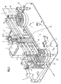
- FIG. 1 We have shown on the figure 1 an image acquisition system 1 integrated in a section of a postal sorting machine 2 according to the invention. For the sake of clarity, some elements of the postal sorting machine section 2 are not shown to better reveal the image acquisition system 1.
- the image acquisition system 1 comprises a housing 3 which has a wall 4 provided with a slot 5 closed by a rigid and transparent wall 6 in front of which are conveyed postal items 7 on edge in a conveying direction indicated by the arrow A and to present to the image acquisition system 1 a surface to be illuminated.
- a lighting module (hereinafter described in correspondence with the figure 4 ) allows to illuminate, through the rigid and transparent wall 6, a surface 8 delimited by the slot 5, corresponding to a portion of the surface of the shipment 7. It will be understood that the surface 8 corresponds to the outer surface of the rigid and transparent wall 6 relative to the housing 3.
- the height of the slot 5 is chosen so that the entire height of the items 7 is illuminated.
- Signs 29 which are, for example, the destination address of the consignment or a bar code in contrast and which serve to automatically sort the items 7.
- the rigid and transparent wall 6 is preferably made of material having characteristics of both high optical transmission and high abrasion resistance, such as for example sapphire. Indeed, a conventional glass is damaged by the passage of the shipments 7 at high speed against the rigid and transparent wall 6 and requires to be changed after the passage of about 1200000 shipments.
- the high abrasion resistance of the sapphire makes it possible, on the contrary, to use the same rigid and transparent wall 6 throughout the life of the image acquisition system 1.
- the presence of polarization filters as described above far in reference to Figures 4 to 6 makes it possible to dispense with slight fluctuations in the polarization of the radiation that can be observed at the exit of a rigid and transparent wall 6 made of sapphire.
- the figure 2 represents the section of a postal sorting machine 2 of the figure 1 , seen from the opposite side.
- the postal sorting machine section 2 comprises a belt conveying device 9 which clamps the shipments 7 between two opposite strips 10, 11 to convey them in the conveying direction A.
- a plating device 12 composed of four wheels 13, 14 , 15,16 with crescent-shaped fins 17 of elastically deformable plastic material and whose respective axes are fixed, plate the shipments 7 in a direction perpendicular to the conveying direction A.
- the four wheels 13,14,15,16 are mounted being spaced from each other in the conveying direction A, on either side of the slot 5 formed in the wall 4 of the housing 3.
- two wheels 15, 16 of the plating device 12 are positioned at a distance of less than dimension of a shipment 7 in the direction indicated by the arrow A, so as to press the mail 7 against the rigid and transparent wall 6.
- the mail 7 thus pressed against this wall is substantially parallel to the rigid and transparent wall 6.
- the rigid and transparent wall 6 limits the deformation of the item 7 during the passage thereof in the mail sorting machine section 2, especially in the case of flexible paper shipments, which allows for to obtain images of the sending 7 acquired by the acquisition system 1 without defect and reproducible.
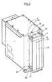
- the figure 3 represents the housing 3 of substantially parallelepipedal shape with the wall 4 provided with the slot 5. More particularly, the wall 4 comprises a removable wall provided with a handle 18 for withdrawing the wall 4 by pulling it upwards and four locking 19 respectively arranged at the top and bottom and on both sides of the removable wall 4. Each locking device 19 comprises a hook 20 fixed in rotation on the removable wall 4 and intended to lock on a lug 21 fixed on the case 3.
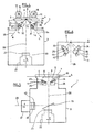
- the figure 4 schematically represents the image acquisition system 1 comprising in the housing 3 a lighting module composed of two lighting units 25,26 arranged to illuminate with a certain oblique angle of incidence the surface 8 delimited by the slot 5 and a camera 22 disposed in the housing 3 to form an image of said surface 8.
- the two lighting units 25,26 are arranged symmetrically on either side of the slot 5 and at a distance from the surface 8 as defined below, which provides a symmetrical illumination of the surface 8.
- the two lighting units 25,26 are substantially identical, as will be detailed later, which ensures an evenly distributed illumination over the entire area. surface 8 and thus makes it possible to reduce, or even eliminate, shadows formed by oblique illumination on flexible items 7, especially of paper, or having surface defects such as folds.
- the camera 22 is arranged so that an optical axis 28 thereof is substantially coincident with a normal to the rigid and transparent wall 6 and the illuminated surface 8. This ensures that the entire surface 8 is at the same distance from the camera 22, which prevents the deformation of the images captured by the camera 22 and facilitates the subsequent processing of these images.
- the slot 5 is preferably centered on the optical axis 28 and the two lighting units 25,26 are therefore arranged symmetrically with respect to the optical axis 28 of the camera 22.
- the images acquired by the first camera 22 are transmitted to an image processing device (not shown) and then processed by it, in a conventional manner for the decoding of the signs 29.
- the image processing could be carried out for example by OCR for sorting mail.
- first optical polarization means composed of a first and a second polarization optical filter 23, 24 producing a linearly polarized light and disposed respectively between the lighting units 25,26 and the illuminated surface 8.
- a third linear polarization optical filter 27 is disposed between the camera 22 and the illuminated surface 8.
- the respective polarization axes of the first and second polarization optical filters 23, 24 are crossed with, or perpendicular to, the polarization axis of the polarization filter 27 disposed between the camera 22 and said illuminated surface 8, ie that is to say that they together form an angle of about 90 °, which makes it possible to reduce or eliminate the shimmering phenomenon of plastic surfaces.
- the third polarization filter 27 is advantageously fixed on a ring (not shown) allowing a rotation adjustment of the polarization axis of the polarization filter 27, in order to easily reach a respective crossing position of the polarization filters 23,24 with the polarization filter 27.
- Additional optical elements may be added in front of the camera 22, and preferably between the third polarization filter 27 and the camera 22 as shown in FIG. figure 4 , in order to improve the quality of the image acquired by the acquisition system 1.
- each lighting unit 25, 26 comprises at least one bar 31 comprising a plurality of light-emitting diodes (LEDs).
- the bars 31 are advantageously arranged longitudinally in the direction of the slot 5 (this is ie perpendicular to the plane of the figure 4 ).
- the distance d 1 must be understood as the distance, in the first illumination incidence direction B, between the middle of the width of the lighting unit 25 (which corresponds to the center of a light-emitting diode) and the intersection between the optical axis 28 and the surface 8, measured at the same height on the lighting unit 25 and the surface 8.
- the camera 22 may be a multi-level gray camera, for example a TDI (Time Delay Integration) multilevel sensor with 64 lines whose resolution is 8 pixels per millimeter (px / mm) and which requires an acquisition area X wide of 8 mm or in a range of about 8 to 10 mm. It is also possible to choose a color camera, for example a "Piranha Color" camera of the Dalsa brand, with a resolution of, for example, between 2 and 8 px / mm and requiring an acquisition zone generally included in a range of about 1 to 5 mm.
- TDI Time Delay Integration
- the LEDs of each lighting unit 25, 26 have a width of at least 5 mm, and the width of each bar 31 has a width of 1.2 in a range of about 8 mm.
- the respective distance d 1.2 between each lighting unit 25, 26 and the surface 8 is then in the range of about 5 to 11 mm when the angles ⁇ , ⁇ are substantially identical and equal to 54.7 °.
- the distance d 1.2 varies in a range of about 5 to 14 mm (about 9 to 14 mm for a multi-level camera gray type of the type described above and about 5 to 11 mm for a color camera of the type described above).
- the slot 5 has a width chosen according to the resolution of the camera 22 and the lighting module 25,26.
- a width of the adapted slot 5 is between 10 mm and 24 mm, in particular to ensure an intensity of satisfactory illumination for producing quality images of the surface 8.
- the two conditions a) and b) above can not be met, especially when the lighting units 25,26 each comprise several bars 31 electroluminescent diodes 32 (as shown in FIG. figure 5 ).
- a satisfactory illumination of said surface 8 can be obtained in this case by choosing angles ⁇ , ⁇ for each strip 31 between about 10 ° and 60 °, and preferably between about 25 ° and 55 °; the respective distance d 1.2 will then be modulated with respect to the angles ⁇ , ⁇ to optimize the illumination of the surface 8, that is to say d 1.2 between about 5 mm and 50 mm, and preferably between about 5 mm and 22 mm.
- the light-emitting diodes 32 will advantageously be chosen from SMD diodes ("Surface-Mounted Components") emitting a white light, which makes it possible to increase the lighting power with respect to conventional light-emitting diodes.
- the arrays 31 of light-emitting diodes 32 are substantially identical to each other in that they comprise substantially identical light-emitting diodes 32, the same number of diodes, the same spacing between the diodes, and so on.
- the light-emitting diodes 32 are spaced apart so that their illuminations overlap on said illuminated surface 8, which makes it possible to obtain uniform illumination over the entire surface 8, in particular over the entire area. height of the surface 8 in the direction of the slot 5.
- an optimum spacing e between light-emitting diodes 32 having a width of 5 mm is in the range of about 5 to 7 mm, for a distance d 1.2 within a range of about 9 to 14 mm, a distance d min in a range of about 2 to 7 mm and light-emitting diodes 32 having an emission angle ⁇ of about 30 °. It goes without saying that other values, in particular the emission angle ⁇ of the light-emitting diodes 32, can be used without departing from the scope of the invention.
- the optimum spacing e between the light-emitting diodes 32 is within a range of about 7 to 40 mm.
- the spacing e The optimum between two consecutive LEDs 32 is in a range of about 1 to 40 mm, where L is the width of such a light emitting diode.
- each light emitting diode is disposed on a bar 31 so that the emitting surface of the diode electroluminescent is parallel to the bar 31 and so as to be oriented towards the surface 8.
- the optical properties of the polarization filters 23,27,24 can not generally be guaranteed for temperatures above 90 ° C.
- An exhaust ventilation system comprising two ventilation columns 35,36 can therefore be arranged in the housing 3 as seen on the figure 4 in order to avoid any instability due to heating of the polarization filters 23,27,24.
- the housing 3 closed by the rigid and transparent wall 6 allows to create an overpressure which facilitates the establishment of the exhaust ventilation system.
- a ventilation column 35, respectively 36 is positioned next to the first lighting unit 25, respectively the second lighting unit 26, providing a homogeneous heat extraction over the entire height of the lighting. Ventilation by heat extraction is advantageous because it does not introduce dust into the image acquisition system 1.
- the figure 5 represents a particular embodiment in which the acquisition system 1 further comprises a second camera 37 arranged to capture at least one image of the illuminated surface 8.
- the first camera 22 may for example be a multi-level gray camera and the second camera 37 a color camera.
- a second camera may be provided for particular applications of the sorting machine section 2, for example to simultaneously perform different processing on images captured by the acquisition system 1.
- An optical axis 38 of the second camera 37 is substantially perpendicular to the optical axis 28 of the first camera 22 on a portion of the path of radiation between the surface 8 and the cameras 22,37.
- a mirror 39 is arranged to allow simultaneous image acquisitions of the illuminated surface 8 by the two cameras 22,37.
- the mirror 39 may be a semi-reflecting separating mirror disposed between the illuminated surface 8 and the first camera 22 so as to pass a first portion of the radiation emitted by the lighting units 25,26 and reflected by the surface 8 in the direction of the first camera 22, and to deflect a second portion of this radiation towards the second camera 37, in a conventional manner, which allows the two cameras 22,37 to simultaneously capture images of the same item 7.
- the first camera 22 is a TDI grayscale multi-level sensor of 64 lines and 8 px / mm resolution, with a wide X acquisition area of 10 mm, while the second camera Color is a linear sensor with a resolution of 1 px / mm and requires a 2 mm Wide Y acquisition area.
- a fourth polarization optical filter 40 is disposed between the second camera 37 and the surface 8 so that a polarization axis of the fourth polarization filter 40 is perpendicular to, or crossed with, each of the polarization axes of the first and second polarization filters 40.
- second polarization filters 23,24 which has the effect of reducing the shimmering effect of surfaces including plastic.
- Other additional optical elements 41 may be added in front of the second camera 37, and preferably between the polarization filter 40 and the camera 37 as indicated on the figure 5 , to further improve the quality of the image acquired by the acquisition system 1.
- the figure 6 represents another particular embodiment of the invention comprising a third and a fourth lighting unit 42, 43, preferably substantially identical to each other, arranged so as to illuminate the surface 8.
- the third and fourth lighting units 42 , 43 are positioned on either side of the slot 5 and so as to direct their illumination on the surface 8, here through the first and second polarization optical filters 23,24.
- Each lighting unit 42, 43 may also be composed of several strips 31 of light emitting diodes 32, not shown, in a manner similar to the lighting units 25, 26 described above.
- the third and fourth lighting units 42, 43 make it possible to improve the lighting on the surface 8, in particular by distributing the lighting on the surface 8 in the direction of the arrow A as a function of the different sensitivity of the cameras 22, 37. For example, it will be possible to increase the intensity of illumination on a central strip of the illuminated surface 8 corresponding to the acquisition zone X, Y of the least sensitive camera and having a narrow acquisition zone. In the example described above, for example, the color camera 37 is less sensitive than the multi-level gray camera 22.
- Two optical elements 44, 45 such as, for example, lenses may be positioned respectively in front of the third and fourth lighting units 42, 43, and preferably between the lighting units 42, 43 and the respective polarization filters 23, 24 as shown on the figure 6 , so as to focus the radiation of the lighting units 42, 43 on a central strip of the surface 8.
- the two cameras 22, 37 not having the same sensitivity can still simultaneously capture images of satisfactory quality for later use an image signature identification technique.
Landscapes
- Engineering & Computer Science (AREA)
- Physics & Mathematics (AREA)
- General Physics & Mathematics (AREA)
- Multimedia (AREA)
- Theoretical Computer Science (AREA)
- Computer Vision & Pattern Recognition (AREA)
- Investigating Materials By The Use Of Optical Means Adapted For Particular Applications (AREA)
- Sorting Of Articles (AREA)
Claims (12)
- Abschnitt einer Postsortiermaschine für Postsendungen (7), welcher eine Fördervorrichtung (9) für Postsendungen (7), die aus elastisch verformbaren Rädern (15, 16) besteht, und ein Bilderfassungssystem (1) zur Identifizierung von Zeichen auf Postsendungen (7) umfasst, und in welchem jede Postsendung durch Festklemmen zwischen der Fördervorrichtung und einer Wand (4) eines Gehäuses (3) fortbewegt wird, in welcher ein Längsschlitz (5) ausgebildet ist, derart, dass bewirkt wird, dass die zu identifizierenden Zeichen, die auf einer Seite der Sendung angebracht sind, in dem Spalt der Wand des Gehäuses erscheinen, wobei das Bilderfassungssystem (1) in dem Gehäuse ein Beleuchtungsmodul (25, 26), das eine von dem Längsschlitz (5) begrenzte Fläche (8) beleuchtet, eine Kamera (22), die so angeordnet ist, dass sie ein Bild der beleuchteten Fläche (8) aufnehmen kann, ein optisches Polarisationsmittel (23, 24), das zwischen dem Beleuchtungsmodul (25, 26) und der beleuchteten Fläche (8) angeordnet ist, und ein optisches Polarisationsfilter (27), das zwischen der Kamera (22) und der beleuchteten Fläche (8) angeordnet ist, umfasst, dadurch gekennzeichnet, dass das Beleuchtungsmodul (25, 26) zwei im Wesentlichen identische Beleuchtungseinheiten (25, 26) umfasst, die symmetrisch beiderseits des Schlitzes (5) angeordnet sind, und dadurch, dass der Schlitz (5) durch eine anliegende durchsichtige starre Wand (6) verschlossen ist, an die jede Sendung (7) durch die elastisch verformbaren Räder (15, 16) angedrückt wird, die beiderseits des Längsschlitzes (5) angeordnet sind, derart, dass die beleuchtete Fläche (8), die der bezüglich des Gehäuses (3) äußeren Fläche der anliegenden durchsichtigen starren Wand (6) gegenüberliegt, die Verformung der Sendung bei ihrem Durchlauf vor dem Schlitz (5) begrenzt.
- Abschnitt einer Postsortiermaschine nach Anspruch 1, wobei jede Beleuchtungseinheit (25, 26) auf die beleuchtete Fläche (8) in einer Einfallsrichtung der Beleuchtung (B, C) mit jeweils einem Einfallswinkel (θ, ϕ) ausgerichtet ist, der in einem Intervall von ungefähr 10 Grad bis 60 Grad liegt, und ein jeweiliger Abstand (d1,2) zwischen jeder Beleuchtungseinheit (25, 26) und der beleuchteten Fläche (8) in der Einfallsrichtung der Beleuchtung (B, C) in einem Intervall von ungefähr 5 Millimetern bis 50 Millimeter liegt.
- Abschnitt einer Postsortiermaschine nach Anspruch 1 oder 2, wobei jede Beleuchtungseinheit (25, 26) wenigstens eine Anordnung (31) von Leuchtdioden (32), die als CMS oder oberflächenmontierte Bauelemente ausgeführt sind und ein weißes Licht aussenden, umfasst.
- Abschnitt einer Postsortiermaschine nach Anspruch 3, wobei ein Zwischenraum zwischen zwei aufeinander folgenden Leuchtdioden (32) einer Anordnung (31) in einem Intervall liegt, das sich von der Breite einer solchen Leuchtdiode bis 40 Millimeter erstreckt.
- Abschnitt einer Postsortiermaschine nach einem der vorhergehenden Ansprüche, wobei eine Breite des Schlitzes (5) in einem Intervall liegt, das sich zwischen ungefähr 10 mm und 24 mm erstreckt.
- Abschnitt einer Postsortiermaschine nach einem der vorhergehenden Ansprüche, wobei die durchsichtige starre Wand (6) aus Saphir hergestellt ist.
- Abschnitt einer Postsortiermaschine nach einem der vorhergehenden Ansprüche, wobei das optische Polarisationsmittel ein erstes und ein zweites optisches Polarisationsfilter (23, 24) umfasst, wobei das erste optische Polarisationsfilter (23) zwischen der ersten Beleuchtungseinheit (25) und der beleuchteten Fläche (8) angeordnet ist und das zweite optische Polarisationsfilter (24) zwischen der zweiten Beleuchtungseinheit (26) und der beleuchteten Fläche (8) angeordnet ist, wobei jeweilige Polarisationsachsen des ersten und des zweiten optischen Polarisationsfilters (23, 24) jeweils senkrecht zu einer Polarisationsachse des optischen Polarisationsfilters (27) sind, das zwischen der Kamera (22) und der beleuchteten Fläche (8) angeordnet ist.
- Abschnitt einer Postsortiermaschine nach einem der vorhergehenden Ansprüche, wobei eine optische Achse (28) der Kamera (22) etwa senkrecht zu der durchsichtigen starren Wand (6) ist.
- Abschnitt einer Postsortiermaschine nach einem der vorhergehenden Ansprüche, welcher außerdem zwei Ventilationssäulen (35, 36) umfasst, die beiderseits des Beleuchtungsmoduls (25, 26) angeordnet sind.
- Abschnitt einer Postsortiermaschine nach einem der vorhergehenden Ansprüche, wobei die Kamera (22) eine erste Kamera für Multi-Graustufen ist, wobei das System außerdem eine zweite Kamera (37) für Farben umfasst, die mit einer zu einer optischen Achse (28) der ersten Kamera (22) senkrechten optischen Achse (38) angeordnet ist, und wobei ein Spiegel (39) derart angeordnet ist, dass er ermöglicht, gleichzeitige Erfassungen von Bildern der beleuchteten Fläche (8) durch die zwei Kameras (22, 37) zu realisieren.
- Abschnitt einer Postsortiermaschine nach Anspruch 10, wobei das Beleuchtungsmodul außerdem zwei weitere Beleuchtungseinheiten (42, 43) umfasst, die symmetrisch beiderseits des Schlitzes (5) angeordnet sind, und derart, dass sie einen mittleren Streifen der Fläche (8) beleuchten, der einem Erfassungsbereich (X, Y) derjenigen Kamera von der ersten und der zweiten Kamera (22, 37) entspricht, welche die weniger empfindliche ist.
- Postsortiermaschine, die einen Abschnitt einer Postsortiermaschine für Postsendungen (7) nach einem der vorhergehenden Ansprüche umfasst, welcher eine Fördervorrichtung (9) umfasst.
Applications Claiming Priority (2)
| Application Number | Priority Date | Filing Date | Title |
|---|---|---|---|
| FR0850640A FR2927179B1 (fr) | 2008-02-01 | 2008-02-01 | Systeme d'acquisition d'images pour l'identification de signes sur des envois postaux. |
| PCT/FR2009/050107 WO2009095602A1 (fr) | 2008-02-01 | 2009-01-26 | Système d'acquisition d'images pour l'identification de signes sur des envois postaux |
Publications (2)
| Publication Number | Publication Date |
|---|---|
| EP2240883A1 EP2240883A1 (de) | 2010-10-20 |
| EP2240883B1 true EP2240883B1 (de) | 2015-06-24 |
Family
ID=39735349
Family Applications (1)
| Application Number | Title | Priority Date | Filing Date |
|---|---|---|---|
| EP09707053.6A Not-in-force EP2240883B1 (de) | 2008-02-01 | 2009-01-26 | Bildaufzeichnungssystem für zeichenidentifikation auf postsendungen |
Country Status (5)
| Country | Link |
|---|---|
| US (1) | US20100182420A1 (de) |
| EP (1) | EP2240883B1 (de) |
| FR (1) | FR2927179B1 (de) |
| PT (1) | PT2240883E (de) |
| WO (1) | WO2009095602A1 (de) |
Families Citing this family (4)
| Publication number | Priority date | Publication date | Assignee | Title |
|---|---|---|---|---|
| AT515236B1 (de) * | 2013-12-23 | 2015-12-15 | Fronius Int Gmbh | Schweißdrahtförderrolle und Vorschubvorrichtung zum Fördern eines Schweißdrahts |
| EP3348334B1 (de) * | 2017-01-17 | 2020-03-04 | Mail Professionals GmbH | Erfassungssysteme und -verfahren für adressdaten auf poststücken |
| IL279275A (en) * | 2020-12-06 | 2022-07-01 | Elbit Systems C4I & Cyber Ltd | Device, systems and methods for scene image acquisition |
| FR3119607B1 (fr) * | 2021-02-09 | 2023-04-28 | Solystic | Dispositif de manipulation mécanique d’un sac souple placé dans un support et installation logistique de tri de colis comprenant un tel dispositif. |
Family Cites Families (15)
| Publication number | Priority date | Publication date | Assignee | Title |
|---|---|---|---|---|
| US3187185A (en) * | 1960-12-22 | 1965-06-01 | United States Steel Corp | Apparatus for determining surface contour |
| US4013999A (en) * | 1974-08-15 | 1977-03-22 | Recognition Equipment Incorporated | Single read station acquisition for character recognition |
| JPS51120718A (en) * | 1975-04-15 | 1976-10-22 | Ricoh Co Ltd | Exposure method for duplicator |
| US4845761A (en) * | 1987-04-17 | 1989-07-04 | Recognition Equipment Incorporated | Letter mail address block locator system |
| JP3546935B2 (ja) * | 1998-12-10 | 2004-07-28 | セイコーエプソン株式会社 | 印刷システム及び同システムのホスト装置 |
| JP3606151B2 (ja) * | 2000-03-02 | 2005-01-05 | 日本電気株式会社 | 画像入力装置 |
| JP4420421B2 (ja) * | 2001-03-19 | 2010-02-24 | キヤノン株式会社 | 情報処理装置およびその制御方法 |
| JPWO2003084210A1 (ja) * | 2002-03-29 | 2005-08-11 | 三菱電機株式会社 | 画像読取装置 |
| JP2004309710A (ja) * | 2003-04-04 | 2004-11-04 | Stanley Electric Co Ltd | 写真撮影用光源装置 |
| JP4467280B2 (ja) * | 2003-10-22 | 2010-05-26 | 富士通株式会社 | 光デバイスモジュール |
| WO2006116029A2 (en) * | 2005-04-21 | 2006-11-02 | Pareskevakos, Theodore, G. | System and method for intelligent currency validation |
| WO2007022985A1 (de) * | 2005-08-26 | 2007-03-01 | Siemens Aktiengesellschaft | System und verfahren zum erkennen von zeichen auf reflektierenden oberflächen |
| US8223208B2 (en) * | 2005-11-10 | 2012-07-17 | Motion Analysis Corporation | Device and method for calibrating an imaging device for generating three dimensional surface models of moving objects |
| FR2895820B1 (fr) * | 2006-01-05 | 2008-07-04 | Solystic Sas | Dispositif d'acquisition d'images d'envois postaux |
| US8073195B2 (en) * | 2007-12-13 | 2011-12-06 | Pitney Bowes Inc. | Method and apparatus for detecting malfunctioning print elements in postage meter indicia printer |
-
2008
- 2008-02-01 FR FR0850640A patent/FR2927179B1/fr not_active Expired - Fee Related
-
2009
- 2009-01-26 EP EP09707053.6A patent/EP2240883B1/de not_active Not-in-force
- 2009-01-26 PT PT97070536T patent/PT2240883E/pt unknown
- 2009-01-26 US US12/442,545 patent/US20100182420A1/en not_active Abandoned
- 2009-01-26 WO PCT/FR2009/050107 patent/WO2009095602A1/fr not_active Ceased
Also Published As
| Publication number | Publication date |
|---|---|
| PT2240883E (pt) | 2015-09-11 |
| FR2927179A1 (fr) | 2009-08-07 |
| FR2927179B1 (fr) | 2010-11-26 |
| EP2240883A1 (de) | 2010-10-20 |
| US20100182420A1 (en) | 2010-07-22 |
| WO2009095602A1 (fr) | 2009-08-06 |
Similar Documents
| Publication | Publication Date | Title |
|---|---|---|
| EP2082216B1 (de) | Verfahren und vorrichtung zum nachweis von niedrigkontrast- und hochkontrastdefekten bei durchsichtigen oder duchscheinenden objekten | |
| EP2238508B1 (de) | Vorrichtung zur erfassung von bildern von postverpackungen mit fluoreszenten markierungen und kontrastmarken | |
| EP2240883B1 (de) | Bildaufzeichnungssystem für zeichenidentifikation auf postsendungen | |
| EP2558847B1 (de) | Verfahren zur detektion von defekten in glaswarenartikeln und installation zur implementierung des besagten verfahrens | |
| EP2912436A1 (de) | Verfahren zur beobachtung biologischer spezies | |
| EP2732273A1 (de) | Verfahren zur erfassung von mehreren bildern desselben pakets mithilfe einer einzigen linearen kamera | |
| FR2874424A1 (fr) | Dispositif d'analyse optique de produits tels que des fruits a eclairage indirect | |
| EP3017398A1 (de) | System zur inspektion eines mindestens durchscheinenden hohlen objekts mit mindestens einer markierung | |
| EP2356049A1 (de) | Verfahren zur kalibrierung in einer maschine zur verarbeitung von plattenförmigen objekten | |
| WO2022195034A1 (fr) | Procédé d'acquisition d'un code marqué sur une feuille de verre ou de vitrocéramique, et système correspondant | |
| EP3465167B1 (de) | Beleuchtungsvorrichtung und verfahren für maschinelles sehen | |
| WO2020157260A1 (fr) | Procede de lecture manuelle d'un code, et dispositif associé | |
| JP2019174150A (ja) | ガラス容器の欠陥検査方法、欠陥検査装置、およびガラス容器検査機 | |
| FR2732626A1 (fr) | Dispositif d'analyse en vue du tri automatique de produits, notamment de fruits ou legumes | |
| EP1770037A1 (de) | Verfahren zum Erkennen von Doppelabzügen von Postsendungen durch Bildanalyse der aufrechten Sendungen | |
| WO1995019605A1 (fr) | Dispositif de lecture d'une marque fluorescente sur un objet | |
| FR2479511A1 (fr) | Perfectionnements aux lecteurs de code electro-optiques | |
| EP0857336B1 (de) | Verfahren und gerät zum identifizieren von zeichen auf mehreren siliziumplättchen | |
| FR2807187A1 (fr) | Procede de comptage d'elements plats agences selon un empilement | |
| EP1971954B1 (de) | Bilderfassungsvorrichtung für postpakete | |
| EP4327295A1 (de) | Vorrichtung zur beleuchtung einer zu prüfenden oberfläche | |
| FR2977695A1 (fr) | Scanner ultra compact a lecture fixe | |
| FR2920567A1 (fr) | Dispositif d'alimentation en articles de courrier a capteur d'images integre | |
| FR3163730A1 (fr) | Système d’acquisition d’une image d’un décor présent sur une face transparente d’un contenant | |
| FR3101144A1 (fr) | Système et procédé de contrôle de la couleur d’un article en déplacement |
Legal Events
| Date | Code | Title | Description |
|---|---|---|---|
| PUAI | Public reference made under article 153(3) epc to a published international application that has entered the european phase |
Free format text: ORIGINAL CODE: 0009012 |
|
| 17P | Request for examination filed |
Effective date: 20091002 |
|
| AK | Designated contracting states |
Kind code of ref document: A1 Designated state(s): AT BE BG CH CY CZ DE DK EE ES FI FR GB GR HR HU IE IS IT LI LT LU LV MC MK MT NL NO PL PT RO SE SI SK TR |
|
| AX | Request for extension of the european patent |
Extension state: AL BA RS |
|
| DAX | Request for extension of the european patent (deleted) | ||
| 17Q | First examination report despatched |
Effective date: 20121012 |
|
| RAP1 | Party data changed (applicant data changed or rights of an application transferred) |
Owner name: SOLYSTIC |
|
| REG | Reference to a national code |
Ref country code: DE Ref legal event code: R079 Ref document number: 602009031846 Country of ref document: DE Free format text: PREVIOUS MAIN CLASS: G06K0009000000 Ipc: G06K0009200000 |
|
| RIC1 | Information provided on ipc code assigned before grant |
Ipc: G06K 9/20 20060101AFI20150115BHEP Ipc: G06K 9/26 20060101ALI20150115BHEP |
|
| GRAP | Despatch of communication of intention to grant a patent |
Free format text: ORIGINAL CODE: EPIDOSNIGR1 |
|
| INTG | Intention to grant announced |
Effective date: 20150310 |
|
| GRAS | Grant fee paid |
Free format text: ORIGINAL CODE: EPIDOSNIGR3 |
|
| GRAA | (expected) grant |
Free format text: ORIGINAL CODE: 0009210 |
|
| AK | Designated contracting states |
Kind code of ref document: B1 Designated state(s): AT BE BG CH CY CZ DE DK EE ES FI FR GB GR HR HU IE IS IT LI LT LU LV MC MK MT NL NO PL PT RO SE SI SK TR |
|
| REG | Reference to a national code |
Ref country code: GB Ref legal event code: FG4D Free format text: NOT ENGLISH |
|
| REG | Reference to a national code |
Ref country code: CH Ref legal event code: EP |
|
| REG | Reference to a national code |
Ref country code: AT Ref legal event code: REF Ref document number: 733205 Country of ref document: AT Kind code of ref document: T Effective date: 20150715 |
|
| REG | Reference to a national code |
Ref country code: IE Ref legal event code: FG4D Free format text: LANGUAGE OF EP DOCUMENT: FRENCH |
|
| REG | Reference to a national code |
Ref country code: DE Ref legal event code: R096 Ref document number: 602009031846 Country of ref document: DE |
|
| REG | Reference to a national code |
Ref country code: NL Ref legal event code: T3 |
|
| REG | Reference to a national code |
Ref country code: PT Ref legal event code: SC4A Free format text: AVAILABILITY OF NATIONAL TRANSLATION Effective date: 20150728 |
|
| REG | Reference to a national code |
Ref country code: SE Ref legal event code: TRGR |
|
| PG25 | Lapsed in a contracting state [announced via postgrant information from national office to epo] |
Ref country code: HR Free format text: LAPSE BECAUSE OF FAILURE TO SUBMIT A TRANSLATION OF THE DESCRIPTION OR TO PAY THE FEE WITHIN THE PRESCRIBED TIME-LIMIT Effective date: 20150624 Ref country code: LT Free format text: LAPSE BECAUSE OF FAILURE TO SUBMIT A TRANSLATION OF THE DESCRIPTION OR TO PAY THE FEE WITHIN THE PRESCRIBED TIME-LIMIT Effective date: 20150624 |
|
| REG | Reference to a national code |
Ref country code: NO Ref legal event code: T2 Effective date: 20150624 |
|
| REG | Reference to a national code |
Ref country code: AT Ref legal event code: MK05 Ref document number: 733205 Country of ref document: AT Kind code of ref document: T Effective date: 20150624 |
|
| REG | Reference to a national code |
Ref country code: LT Ref legal event code: MG4D |
|
| PG25 | Lapsed in a contracting state [announced via postgrant information from national office to epo] |
Ref country code: GR Free format text: LAPSE BECAUSE OF FAILURE TO SUBMIT A TRANSLATION OF THE DESCRIPTION OR TO PAY THE FEE WITHIN THE PRESCRIBED TIME-LIMIT Effective date: 20150925 Ref country code: BG Free format text: LAPSE BECAUSE OF FAILURE TO SUBMIT A TRANSLATION OF THE DESCRIPTION OR TO PAY THE FEE WITHIN THE PRESCRIBED TIME-LIMIT Effective date: 20150924 Ref country code: LV Free format text: LAPSE BECAUSE OF FAILURE TO SUBMIT A TRANSLATION OF THE DESCRIPTION OR TO PAY THE FEE WITHIN THE PRESCRIBED TIME-LIMIT Effective date: 20150624 |
|
| REG | Reference to a national code |
Ref country code: FR Ref legal event code: PLFP Year of fee payment: 8 |
|
| PG25 | Lapsed in a contracting state [announced via postgrant information from national office to epo] |
Ref country code: EE Free format text: LAPSE BECAUSE OF FAILURE TO SUBMIT A TRANSLATION OF THE DESCRIPTION OR TO PAY THE FEE WITHIN THE PRESCRIBED TIME-LIMIT Effective date: 20150624 |
|
| PG25 | Lapsed in a contracting state [announced via postgrant information from national office to epo] |
Ref country code: RO Free format text: LAPSE BECAUSE OF NON-PAYMENT OF DUE FEES Effective date: 20150624 Ref country code: PL Free format text: LAPSE BECAUSE OF FAILURE TO SUBMIT A TRANSLATION OF THE DESCRIPTION OR TO PAY THE FEE WITHIN THE PRESCRIBED TIME-LIMIT Effective date: 20150624 Ref country code: IS Free format text: LAPSE BECAUSE OF FAILURE TO SUBMIT A TRANSLATION OF THE DESCRIPTION OR TO PAY THE FEE WITHIN THE PRESCRIBED TIME-LIMIT Effective date: 20151024 Ref country code: AT Free format text: LAPSE BECAUSE OF FAILURE TO SUBMIT A TRANSLATION OF THE DESCRIPTION OR TO PAY THE FEE WITHIN THE PRESCRIBED TIME-LIMIT Effective date: 20150624 Ref country code: SK Free format text: LAPSE BECAUSE OF FAILURE TO SUBMIT A TRANSLATION OF THE DESCRIPTION OR TO PAY THE FEE WITHIN THE PRESCRIBED TIME-LIMIT Effective date: 20150624 Ref country code: CZ Free format text: LAPSE BECAUSE OF FAILURE TO SUBMIT A TRANSLATION OF THE DESCRIPTION OR TO PAY THE FEE WITHIN THE PRESCRIBED TIME-LIMIT Effective date: 20150624 Ref country code: ES Free format text: LAPSE BECAUSE OF FAILURE TO SUBMIT A TRANSLATION OF THE DESCRIPTION OR TO PAY THE FEE WITHIN THE PRESCRIBED TIME-LIMIT Effective date: 20150624 |
|
| REG | Reference to a national code |
Ref country code: DE Ref legal event code: R097 Ref document number: 602009031846 Country of ref document: DE |
|
| PG25 | Lapsed in a contracting state [announced via postgrant information from national office to epo] |
Ref country code: DK Free format text: LAPSE BECAUSE OF FAILURE TO SUBMIT A TRANSLATION OF THE DESCRIPTION OR TO PAY THE FEE WITHIN THE PRESCRIBED TIME-LIMIT Effective date: 20150624 Ref country code: IT Free format text: LAPSE BECAUSE OF FAILURE TO SUBMIT A TRANSLATION OF THE DESCRIPTION OR TO PAY THE FEE WITHIN THE PRESCRIBED TIME-LIMIT Effective date: 20150624 |
|
| PLBE | No opposition filed within time limit |
Free format text: ORIGINAL CODE: 0009261 |
|
| STAA | Information on the status of an ep patent application or granted ep patent |
Free format text: STATUS: NO OPPOSITION FILED WITHIN TIME LIMIT |
|
| 26N | No opposition filed |
Effective date: 20160329 |
|
| PG25 | Lapsed in a contracting state [announced via postgrant information from national office to epo] |
Ref country code: LU Free format text: LAPSE BECAUSE OF FAILURE TO SUBMIT A TRANSLATION OF THE DESCRIPTION OR TO PAY THE FEE WITHIN THE PRESCRIBED TIME-LIMIT Effective date: 20160126 Ref country code: SI Free format text: LAPSE BECAUSE OF FAILURE TO SUBMIT A TRANSLATION OF THE DESCRIPTION OR TO PAY THE FEE WITHIN THE PRESCRIBED TIME-LIMIT Effective date: 20150624 |
|
| REG | Reference to a national code |
Ref country code: CH Ref legal event code: PL |
|
| PG25 | Lapsed in a contracting state [announced via postgrant information from national office to epo] |
Ref country code: MC Free format text: LAPSE BECAUSE OF FAILURE TO SUBMIT A TRANSLATION OF THE DESCRIPTION OR TO PAY THE FEE WITHIN THE PRESCRIBED TIME-LIMIT Effective date: 20150624 |
|
| PG25 | Lapsed in a contracting state [announced via postgrant information from national office to epo] |
Ref country code: LI Free format text: LAPSE BECAUSE OF NON-PAYMENT OF DUE FEES Effective date: 20160131 Ref country code: CH Free format text: LAPSE BECAUSE OF NON-PAYMENT OF DUE FEES Effective date: 20160131 |
|
| REG | Reference to a national code |
Ref country code: IE Ref legal event code: MM4A |
|
| REG | Reference to a national code |
Ref country code: FR Ref legal event code: PLFP Year of fee payment: 9 |
|
| PG25 | Lapsed in a contracting state [announced via postgrant information from national office to epo] |
Ref country code: IE Free format text: LAPSE BECAUSE OF NON-PAYMENT OF DUE FEES Effective date: 20160126 |
|
| PG25 | Lapsed in a contracting state [announced via postgrant information from national office to epo] |
Ref country code: MT Free format text: LAPSE BECAUSE OF FAILURE TO SUBMIT A TRANSLATION OF THE DESCRIPTION OR TO PAY THE FEE WITHIN THE PRESCRIBED TIME-LIMIT Effective date: 20150624 |
|
| REG | Reference to a national code |
Ref country code: FR Ref legal event code: PLFP Year of fee payment: 10 |
|
| PG25 | Lapsed in a contracting state [announced via postgrant information from national office to epo] |
Ref country code: CY Free format text: LAPSE BECAUSE OF FAILURE TO SUBMIT A TRANSLATION OF THE DESCRIPTION OR TO PAY THE FEE WITHIN THE PRESCRIBED TIME-LIMIT Effective date: 20150624 Ref country code: HU Free format text: LAPSE BECAUSE OF FAILURE TO SUBMIT A TRANSLATION OF THE DESCRIPTION OR TO PAY THE FEE WITHIN THE PRESCRIBED TIME-LIMIT; INVALID AB INITIO Effective date: 20090126 |
|
| PG25 | Lapsed in a contracting state [announced via postgrant information from national office to epo] |
Ref country code: MK Free format text: LAPSE BECAUSE OF FAILURE TO SUBMIT A TRANSLATION OF THE DESCRIPTION OR TO PAY THE FEE WITHIN THE PRESCRIBED TIME-LIMIT Effective date: 20150624 Ref country code: TR Free format text: LAPSE BECAUSE OF FAILURE TO SUBMIT A TRANSLATION OF THE DESCRIPTION OR TO PAY THE FEE WITHIN THE PRESCRIBED TIME-LIMIT Effective date: 20150624 |
|
| PGFP | Annual fee paid to national office [announced via postgrant information from national office to epo] |
Ref country code: NO Payment date: 20200123 Year of fee payment: 12 Ref country code: DE Payment date: 20200121 Year of fee payment: 12 Ref country code: NL Payment date: 20200121 Year of fee payment: 12 Ref country code: GB Payment date: 20200124 Year of fee payment: 12 Ref country code: PT Payment date: 20200120 Year of fee payment: 12 Ref country code: SE Payment date: 20200121 Year of fee payment: 12 Ref country code: FI Payment date: 20200122 Year of fee payment: 12 |
|
| PGFP | Annual fee paid to national office [announced via postgrant information from national office to epo] |
Ref country code: BE Payment date: 20200121 Year of fee payment: 12 |
|
| PGFP | Annual fee paid to national office [announced via postgrant information from national office to epo] |
Ref country code: FR Payment date: 20200117 Year of fee payment: 12 |
|
| REG | Reference to a national code |
Ref country code: DE Ref legal event code: R119 Ref document number: 602009031846 Country of ref document: DE |
|
| REG | Reference to a national code |
Ref country code: FI Ref legal event code: MAE |
|
| REG | Reference to a national code |
Ref country code: NO Ref legal event code: MMEP |
|
| REG | Reference to a national code |
Ref country code: SE Ref legal event code: EUG |
|
| REG | Reference to a national code |
Ref country code: NL Ref legal event code: MM Effective date: 20210201 |
|
| GBPC | Gb: european patent ceased through non-payment of renewal fee |
Effective date: 20210126 |
|
| REG | Reference to a national code |
Ref country code: BE Ref legal event code: MM Effective date: 20210131 |
|
| PG25 | Lapsed in a contracting state [announced via postgrant information from national office to epo] |
Ref country code: FR Free format text: LAPSE BECAUSE OF NON-PAYMENT OF DUE FEES Effective date: 20210131 Ref country code: FI Free format text: LAPSE BECAUSE OF NON-PAYMENT OF DUE FEES Effective date: 20210126 Ref country code: NL Free format text: LAPSE BECAUSE OF NON-PAYMENT OF DUE FEES Effective date: 20210201 |
|
| PG25 | Lapsed in a contracting state [announced via postgrant information from national office to epo] |
Ref country code: SE Free format text: LAPSE BECAUSE OF NON-PAYMENT OF DUE FEES Effective date: 20210127 Ref country code: PT Free format text: LAPSE BECAUSE OF NON-PAYMENT OF DUE FEES Effective date: 20210726 Ref country code: NO Free format text: LAPSE BECAUSE OF NON-PAYMENT OF DUE FEES Effective date: 20210131 Ref country code: GB Free format text: LAPSE BECAUSE OF NON-PAYMENT OF DUE FEES Effective date: 20210126 Ref country code: DE Free format text: LAPSE BECAUSE OF NON-PAYMENT OF DUE FEES Effective date: 20210803 |
|
| PG25 | Lapsed in a contracting state [announced via postgrant information from national office to epo] |
Ref country code: BE Free format text: LAPSE BECAUSE OF NON-PAYMENT OF DUE FEES Effective date: 20210131 |