EP2241212A1 - Paillasse de laboratoire et système comprenant plusieurs paillasses de laboratoire - Google Patents
Paillasse de laboratoire et système comprenant plusieurs paillasses de laboratoire Download PDFInfo
- Publication number
- EP2241212A1 EP2241212A1 EP10158866A EP10158866A EP2241212A1 EP 2241212 A1 EP2241212 A1 EP 2241212A1 EP 10158866 A EP10158866 A EP 10158866A EP 10158866 A EP10158866 A EP 10158866A EP 2241212 A1 EP2241212 A1 EP 2241212A1
- Authority
- EP
- European Patent Office
- Prior art keywords
- rail
- container module
- work table
- laboratory
- laboratory work
- Prior art date
- Legal status (The legal status is an assumption and is not a legal conclusion. Google has not performed a legal analysis and makes no representation as to the accuracy of the status listed.)
- Withdrawn
Links
Images


Classifications
-
- A—HUMAN NECESSITIES
- A47—FURNITURE; DOMESTIC ARTICLES OR APPLIANCES; COFFEE MILLS; SPICE MILLS; SUCTION CLEANERS IN GENERAL
- A47B—TABLES; DESKS; OFFICE FURNITURE; CABINETS; DRAWERS; GENERAL DETAILS OF FURNITURE
- A47B37/00—Tables adapted for other particular purposes
-
- A—HUMAN NECESSITIES
- A47—FURNITURE; DOMESTIC ARTICLES OR APPLIANCES; COFFEE MILLS; SPICE MILLS; SUCTION CLEANERS IN GENERAL
- A47B—TABLES; DESKS; OFFICE FURNITURE; CABINETS; DRAWERS; GENERAL DETAILS OF FURNITURE
- A47B17/00—Writing-tables
- A47B17/03—Writing-tables with substantially horizontally extensible or adjustable parts other than drawers, e.g. leaves
- A47B17/036—Writing-tables with substantially horizontally extensible or adjustable parts other than drawers, e.g. leaves with sliding or unfolding parts other than leaves or drawers
-
- B—PERFORMING OPERATIONS; TRANSPORTING
- B01—PHYSICAL OR CHEMICAL PROCESSES OR APPARATUS IN GENERAL
- B01L—CHEMICAL OR PHYSICAL LABORATORY APPARATUS FOR GENERAL USE
- B01L9/00—Supporting devices; Holding devices
- B01L9/02—Laboratory benches or tables; Fittings therefor
Definitions
- the invention relates to a laboratory work table and a system comprising a plurality of laboratory work tables.
- Laboratory work tables are used to perform various laboratory tests.
- container modules are used for the storage of laboratory utensils.
- Such as storage space serving container modules are usually placed below the worktop of the laboratory work table and are firmly connected to the table frame.
- the container module itself serves as a table frame or support element for the worktop of the laboratory worktable.
- a laboratory work table in which a container module is provided translationally displaceable in the width direction, known.
- a support element is provided on a lower region on the rear side of the container module, which engages in a rail mounted on the table frame.
- pivotable support bracket In a front region of the side surfaces of the container module pivotable support bracket are provided, which can be pivoted for suspending the entire container module such that they engage in a mounted in the front upper portion of the table frame rail.
- a disadvantage of this container module is that the support bracket attached to the outside of the container module are subjected to shear when moving the container module in such a way that it can lead to a bending of the support bracket or a tearing of the support bracket fixing screws.
- the laboratory work table comprises a container module arranged below the work surface of the laboratory work table and translationally movable in the width direction of the laboratory work table.
- the advantage of this is that a person working on the laboratory work table can move the container module in the Beitencardi depending on the activity and need. Moreover, such a made easier Laboratory work table cleaning the floor area below the table.
- the object is achieved by a system having the features of claim 13.
- the system comprises several laboratory work tables, whereby the container module can be translationally moved across the laboratory worktops in the width direction.
- the advantage here is that a person working on the work tables person can move the container module over long distances as needed to a suitable position.
- Fig. 1 is a side view of a laboratory work table according to the invention (hereinafter referred to as a work table) shown, wherein the X-axis of the in Fig. 1 shown coordinate system in the depth direction, the Y-axis in the width direction and the Z-axis in the height direction of the work table show.
- the position V in Fig. 1 indicates the front side of the worktable 1, ie the side on which, under normal conditions Using the work table 1 is a person, and the position R is in Fig. 1 the back of the work table 1 on.
- the in Fig. 1 shown work table has a table frame 4, which carries a countertop 2. More specifically, in this embodiment, the table frame 4 is formed of at least two C-frames 41, which are connected via three strut elements 42. Depending on the width of the worktop 2, the strut elements 42 are arranged at a predetermined distance. Each of the C-frames 41 is formed so as to include two sections 43 extending in the depth direction of the work table and a section 44 located on the rear side R. The extending in height direction of the table section 44 also defines the height of the table substantially.
- a container module 3 which serves as a receiving space for tools or equipment.
- the container module can be designed, for example, as a drawer module or as a receiving space provided with doors.
- the work table 1 and the Contalnermodul 3 via a first rail means 5 and a second rail means 6 are connected such that the container module in the Y direction, ie in the width direction of the work table 1 can be moved continuously.
- the first rail device 5 is arranged between the worktop 2 and an upper side 31 of the container module 3. More precisely, the rail device 5 is located in a front area, ie in the vicinity of the front side V of the worktable 1 between the worktop 2 and the upper side 31 of the container module 3.
- the first rail device 5 comprises a rail 51 connected to the worktable 1.
- the rail 51 in FIG the in Fig. 1 illustrated embodiment of the strut element 42 is attached, and connected to the container module 3 rail support member 52nd
- the rail 51 is fixed in this embodiment to the strut element 42 of the Tischgesiells 4, but can also be attached to an underside 22 of the worktop 2 as needed.
- the rail support element 52 can be secured in the interior of the container module 3 through a corresponding passage opening.
- the rail support element 52 is designed in this embodiment as an angled element, which engages in the rail 51 and together with this forms a lower (x-y plane) and a lateral (y-z plane) sliding surface. It should be mentioned at this point that only one sliding surface is sufficient for the correct functioning.
- the rail support member 52 is formed as an L-shaped rail support member passing through the opening in the work top facing upper side of the container module, wherein a first free end 53 of the L-shaped rail support member is mounted inside the container module and a second free end 54 movably rests on the rail.
- the first free end 53 of the L-shaped rail support element is fastened, for example, by means of a screw either on the upper side 31 of the container module or on the side wall of the container module.
- the opening formed in the upper side 31 of the container module at least in the width direction (y direction) is dimensioned such that the rail support element 52 abuts exactly on the upper side of the container module or the upper side of the container module terminates on the rail support element 52.
- the L-shaped rail support element fits exactly into the opening at least in the width direction. This will be advantageous way Shear forces that occur when moving the container module, effectively introduced into the container module or its upper side 31.
- the rail support member 52 forms with the rail 51 at least one sliding surface. More specifically, the second free end 54 of the L-shaped rail support member 52 engages the rail 51 such that the second free end engages a sliding surface in the in FIG. 1 shown xy plane and one formed in the yz plane shown. Both by the dimensioning of the opening, such that the upper side 31 terminates at the rail support element 52, and by forming the at least one sliding surface of the second free end with the rail 51 occur at the attachment of Schienenaufiageiatas within the container module extremely low bending stresses and Moments up.
- the rail support element 52 in the width direction are arbitrarily dimensioned.
- the L-shaped rail support member 52 may be dimensioned in the width direction so that it extends within the container module through the entire interior in the width direction.
- the L-shaped rail support element or angle element explained here is to be understood as meaning an angle element which has at least one L-shaped section whose first end is fastened in the interior of the container module and whose second end engages in the rail 51.
- a further second rail device 6 is provided.
- This rail device 6 comprises a rail 61, which is connected to the table frame 4 of the work table 1, and a rail support element 62, which is attached to the container module 3.
- the rail support element 62 is in this embodiment, as in Fig. 1 can be seen, arranged on a rear side 32 of the container module 3 and connected to accommodate weight forces with the container module 3 via three screws.
- Fig. 2 is the second rail device 6 or in Fig. 1 shown area A shown enlarged.
- the rail 61 of the second rail device 6 is connected to the strut element 42 of the table frame 4.
- the rail 61 has, at its end which interacts with the rail support element 62, a bent region 63 which engages in a notched region or groove 64 formed in the rail support element 62. It should be noted at this point that this engagement of the notch or groove 64 and the bent end 63 can also be done in the reverse manner. More precisely, this means that the notch or groove 64 can be formed in the rail 61, in which a corresponding counterpart of the rail support element 62 engages.
- the container module When the container module 3 is suspended via the rail devices 5, 6, the container module can be moved translationally along the width direction (Y direction) as required. During such movement, the rail support element 52 of the first rail device 5 slides in the rail 51 and the rail support element 62 of the second rail device 6 on the rail 61. Both rail support elements 52, 62 may be formed as a block of polytetrafluoroethylene or coated therewith.
- both the rail support element 52 of the first rail device 5 and the rail support element 62 of the second rail device 6, seen from the front side V of the work table, is arranged in front of the heightwise extending section 44. Consequently, the rail support members 52, 62 are guided within the C-section of the C-leg frame. In the in Fig. 1 In the embodiment shown, this guide is achieved by the rail 51 of the first rail device 5 and the rail 61 of the second rail device 6 having such dimensions that the rail support elements are arranged below or in front of the corresponding sections 43, 44 of the C-foot.
- the container module can be moved across all work tables away, because the rail support members 52, 62 do not hit the C-legs of the lined work tables 1.
- the rails of the rail devices 5, 6 merge into each other. Another way to ensure a transition between the rails 51, 52 is to provide suitable adapter rails.
- Fig. 1 is a stop which is connected via a screw to the rail 51, visible visible.
- a system can be created from a plurality of work tables with translatorily movably arranged container modules.
- Fig. 3 a second preferred embodiment of a work table according to the invention is shown.
- the elements which correspond to those of the first embodiment are provided with the same reference numerals and will not be explained again at this point,
- the table frame is 2-4.
- This includes two H-frames 2-41, which are connected to each other via strut members 42 as in the first embodiment.
- the H-frames each have two vertically parallel portions 2-44 and a widthwise extending portion 2-43, the the heightwise sections 2-44 connects.
- the container module 3 is connected to the work table 2-1 via two rail devices 5, 2-6 as in the first embodiment.
- the first rail device 5 is arranged between the work surface 2 and an upper side 31 of the container module 3 and corresponds to the rail device 5 of the first embodiment.
- the second rail device 2-6 differs from that of the first embodiment.
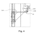
- the in Fig. 3 shown area B is in Fig. 4 shown enlarged.
- the second rail device 2-6 comprises a rail support element 2-62 fixed on a lower side 33 of the container module 3, and a rail 2-61 fixed to the strut element 42.
- the rail 2-61 engages with a bent end 2 -63 in a groove formed in the rail support member 2-62, wherein, as in the first embodiment, a notch or groove in the rail 2-61, in which a corresponding counterpart of the rail support member 2-62 engages, may be formed.
- Weight forces can be absorbed by this intermeshing of the rail 2-61 and the rail support element 2-62 and the container module 3 can be guided during the translatory movement.
- the shape of the cradles is not limited to the C-shape and H-shape shown in the figures.
- the invention can also be realized in laboratory work tables, the pedestals a Cantilever- or have reverse L-shape.
- a cantilever pedestal comprises at least two cantilever beams, one of which extends in a horizontal direction and serves as a support for the worktop. The other cantilever runs in the vertical direction and is usually attached to a wall.
- the rail support elements slide in the associated rails.
- the rail support elements and / or the rails may be coated with a friction reducing material.
- the preferred material here has been found to be polytetrafluoroethylene,
- the rail support elements as roller elements that run in the rails.
- a single or multiple rail support elements may be provided. This applies to the first and second rail device.
- the rail means as seen in the side view, are arranged at diagonally opposite positions. But it is also possible to arrange the second rail device 6, 2-6 between the worktop 2 and a top 31 of the container module. In this case, the container module hangs on two rail devices arranged between the container module and the worktop.
- the two outer leg rests may be designed as H-legs and the intermediate leg rests may be C-leg rests be.
- the H-frames take over the function of a stop here.
- Another advantage that results from the translationally displaceable arrangement of the container module (or more container modules), is that the space below the container module for cleaning personnel is easily accessible, which can significantly reduce the cleaning costs of a large-scale laboratory.
Landscapes
- Health & Medical Sciences (AREA)
- Clinical Laboratory Science (AREA)
- Chemical & Material Sciences (AREA)
- Chemical Kinetics & Catalysis (AREA)
- Devices For Use In Laboratory Experiments (AREA)
Applications Claiming Priority (1)
| Application Number | Priority Date | Filing Date | Title |
|---|---|---|---|
| DE200910002460 DE102009002460A1 (de) | 2009-04-17 | 2009-04-17 | Laborarbeitstisch und System umfassend mehrere Laborarbeitstische |
Publications (1)
| Publication Number | Publication Date |
|---|---|
| EP2241212A1 true EP2241212A1 (fr) | 2010-10-20 |
Family
ID=42235880
Family Applications (1)
| Application Number | Title | Priority Date | Filing Date |
|---|---|---|---|
| EP10158866A Withdrawn EP2241212A1 (fr) | 2009-04-17 | 2010-03-31 | Paillasse de laboratoire et système comprenant plusieurs paillasses de laboratoire |
Country Status (2)
| Country | Link |
|---|---|
| EP (1) | EP2241212A1 (fr) |
| DE (1) | DE102009002460A1 (fr) |
Cited By (2)
| Publication number | Priority date | Publication date | Assignee | Title |
|---|---|---|---|---|
| CN105126946A (zh) * | 2015-09-14 | 2015-12-09 | 陈海霞 | 一种病理诊断用多功能取材台 |
| CN114471781A (zh) * | 2022-02-25 | 2022-05-13 | 湖南擎晟医疗器械科技有限责任公司 | 一种带传递功能的实验室操作台 |
Families Citing this family (1)
| Publication number | Priority date | Publication date | Assignee | Title |
|---|---|---|---|---|
| DE102011055655B4 (de) | 2011-11-23 | 2020-07-16 | Waldner Labor- Und Schuleinrichtungen Gmbh | Gehäuse für eine Medienversorgung |
Citations (2)
| Publication number | Priority date | Publication date | Assignee | Title |
|---|---|---|---|---|
| DE2419034A1 (de) | 1974-04-19 | 1975-11-06 | Schaik & Berghuis | Labortisch |
| EP1088497A2 (fr) * | 1999-09-28 | 2001-04-04 | Elmar S.r.l. | Meuble comprenant un plan de travail escamotable, notamment pour des cuisines ou d'autres ameublements |
Family Cites Families (4)
| Publication number | Priority date | Publication date | Assignee | Title |
|---|---|---|---|---|
| DE7113624U (de) * | 1971-07-08 | Herrmann G | Fahrbarer Unterbau fur Labortische | |
| DE2710756C2 (de) * | 1977-03-11 | 1985-12-19 | Kaltenbach & Voigt Gmbh & Co, 7950 Biberach | Zahnärztliches Lehr- und Übungsgerät |
| DE8619969U1 (de) * | 1986-07-25 | 1988-07-07 | Selecta-Werk Gmbh Bank- Und Kasseneinrichtungen, 5760 Arnsberg | Arbeitstisch, insbesondere Bürotisch |
| US20060024212A1 (en) * | 2004-08-02 | 2006-02-02 | Hwang David S | Analytical equipment cart |
-
2009
- 2009-04-17 DE DE200910002460 patent/DE102009002460A1/de not_active Ceased
-
2010
- 2010-03-31 EP EP10158866A patent/EP2241212A1/fr not_active Withdrawn
Patent Citations (2)
| Publication number | Priority date | Publication date | Assignee | Title |
|---|---|---|---|---|
| DE2419034A1 (de) | 1974-04-19 | 1975-11-06 | Schaik & Berghuis | Labortisch |
| EP1088497A2 (fr) * | 1999-09-28 | 2001-04-04 | Elmar S.r.l. | Meuble comprenant un plan de travail escamotable, notamment pour des cuisines ou d'autres ameublements |
Cited By (2)
| Publication number | Priority date | Publication date | Assignee | Title |
|---|---|---|---|---|
| CN105126946A (zh) * | 2015-09-14 | 2015-12-09 | 陈海霞 | 一种病理诊断用多功能取材台 |
| CN114471781A (zh) * | 2022-02-25 | 2022-05-13 | 湖南擎晟医疗器械科技有限责任公司 | 一种带传递功能的实验室操作台 |
Also Published As
| Publication number | Publication date |
|---|---|
| DE102009002460A1 (de) | 2010-11-11 |
Similar Documents
| Publication | Publication Date | Title |
|---|---|---|
| EP0362614B1 (fr) | Dispositif pour poste de travail pour bureau | |
| DE2424484C2 (de) | Möbelsystem | |
| DE102015105827A1 (de) | Tischgestell für einen Tisch | |
| EP2531064A1 (fr) | Tiroir pour meuble | |
| DE3727193A1 (de) | Arbeitstisch | |
| DE9007599U1 (de) | Geräteträger | |
| AT519407B1 (de) | Bearbeitungsanlage für Platten und dergleichen und mit dieser Anlage verwirklichte Produktionslinie | |
| DE3444580C2 (de) | Einrichtung zum Untersuchen der Augen | |
| EP2241212A1 (fr) | Paillasse de laboratoire et système comprenant plusieurs paillasses de laboratoire | |
| EP1242212B1 (fr) | Machine-outil | |
| EP2241220B1 (fr) | Placard de hauteur d'étage | |
| DE19911412A1 (de) | Werkzeugmaschine | |
| DE10144028A1 (de) | Maschinengestell in Modulbauweise | |
| EP3456220B1 (fr) | Système de poste de travail avec zone de montage flexible | |
| EP0338210B1 (fr) | Dispositif médical d'alimentation | |
| DE102014012527A1 (de) | Schweißtisch sowie Gestell zur Verwendung mit einem Schweißtisch | |
| DE102011006352B4 (de) | Flexible Arbeitsstation mit einem ergonomisch individuellen Arbeitsplatz | |
| EP2712516A2 (fr) | Système de levage pour un système de poste de travail réglable en hauteur et système de poste de travail doté d'un tel système de levage | |
| DE3934138A1 (de) | Bildschirmarbeitsplatz | |
| DE202008016891U1 (de) | Laborarbeitsplatz | |
| DE202012005260U1 (de) | Monitorpositionierungsvorrichtung | |
| EP0551639A1 (fr) | Pied pour table de bureau, de laboratoire ou de travail | |
| EP2134214B1 (fr) | Système guide-câble | |
| DE102004046614B4 (de) | Ophthalmologischer Arbeitsplatz | |
| WO1992007488A1 (fr) | Table de travail a plusieurs plateaux de travail |
Legal Events
| Date | Code | Title | Description |
|---|---|---|---|
| PUAI | Public reference made under article 153(3) epc to a published international application that has entered the european phase |
Free format text: ORIGINAL CODE: 0009012 |
|
| AK | Designated contracting states |
Kind code of ref document: A1 Designated state(s): AT BE BG CH CY CZ DE DK EE ES FI FR GB GR HR HU IE IS IT LI LT LU LV MC MK MT NL NO PL PT RO SE SI SK SM TR |
|
| AX | Request for extension of the european patent |
Extension state: AL BA ME RS |
|
| 17P | Request for examination filed |
Effective date: 20110302 |
|
| GRAP | Despatch of communication of intention to grant a patent |
Free format text: ORIGINAL CODE: EPIDOSNIGR1 |
|
| INTG | Intention to grant announced |
Effective date: 20140303 |
|
| RIN1 | Information on inventor provided before grant (corrected) |
Inventor name: LIEBSCH, JUERGEN |
|
| STAA | Information on the status of an ep patent application or granted ep patent |
Free format text: STATUS: THE APPLICATION IS DEEMED TO BE WITHDRAWN |
|
| 18D | Application deemed to be withdrawn |
Effective date: 20140715 |