EP2241348B1 - Dispositif de surveillance cardiaque - Google Patents
Dispositif de surveillance cardiaque Download PDFInfo
- Publication number
- EP2241348B1 EP2241348B1 EP20100156625 EP10156625A EP2241348B1 EP 2241348 B1 EP2241348 B1 EP 2241348B1 EP 20100156625 EP20100156625 EP 20100156625 EP 10156625 A EP10156625 A EP 10156625A EP 2241348 B1 EP2241348 B1 EP 2241348B1
- Authority
- EP
- European Patent Office
- Prior art keywords
- evaluation unit
- signal value
- diagram
- value pairs
- heart
- Prior art date
- Legal status (The legal status is an assumption and is not a legal conclusion. Google has not performed a legal analysis and makes no representation as to the accuracy of the status listed.)
- Not-in-force
Links
- 210000002216 heart Anatomy 0.000 title claims description 79
- 238000011156 evaluation Methods 0.000 claims description 82
- 238000010586 diagram Methods 0.000 claims description 64
- 230000000747 cardiac effect Effects 0.000 claims description 33
- 239000003550 marker Substances 0.000 claims description 14
- 230000000638 stimulation Effects 0.000 claims description 14
- 238000005381 potential energy Methods 0.000 claims description 6
- 230000006870 function Effects 0.000 claims description 5
- 239000013598 vector Substances 0.000 claims description 5
- 230000008878 coupling Effects 0.000 claims description 3
- 238000010168 coupling process Methods 0.000 claims description 3
- 238000005859 coupling reaction Methods 0.000 claims description 3
- 230000036316 preload Effects 0.000 claims description 3
- 230000001052 transient effect Effects 0.000 claims description 3
- 238000004364 calculation method Methods 0.000 claims description 2
- 230000000877 morphologic effect Effects 0.000 claims description 2
- 238000012545 processing Methods 0.000 claims description 2
- 230000002861 ventricular Effects 0.000 description 14
- 238000005259 measurement Methods 0.000 description 10
- 239000008280 blood Substances 0.000 description 7
- 210000004369 blood Anatomy 0.000 description 7
- 239000007943 implant Substances 0.000 description 7
- 230000002107 myocardial effect Effects 0.000 description 7
- 230000008859 change Effects 0.000 description 6
- 238000000034 method Methods 0.000 description 5
- 206010015856 Extrasystoles Diseases 0.000 description 4
- TZCXTZWJZNENPQ-UHFFFAOYSA-L barium sulfate Chemical compound [Ba+2].[O-]S([O-])(=O)=O TZCXTZWJZNENPQ-UHFFFAOYSA-L 0.000 description 4
- 238000009530 blood pressure measurement Methods 0.000 description 4
- 210000005242 cardiac chamber Anatomy 0.000 description 4
- 230000008602 contraction Effects 0.000 description 4
- 238000011161 development Methods 0.000 description 4
- 230000018109 developmental process Effects 0.000 description 4
- 210000005240 left ventricle Anatomy 0.000 description 4
- 210000004165 myocardium Anatomy 0.000 description 4
- QVGXLLKOCUKJST-UHFFFAOYSA-N atomic oxygen Chemical compound [O] QVGXLLKOCUKJST-UHFFFAOYSA-N 0.000 description 3
- 210000003748 coronary sinus Anatomy 0.000 description 3
- 229910052760 oxygen Inorganic materials 0.000 description 3
- 239000001301 oxygen Substances 0.000 description 3
- 230000011218 segmentation Effects 0.000 description 3
- 208000000418 Premature Cardiac Complexes Diseases 0.000 description 2
- 238000009125 cardiac resynchronization therapy Methods 0.000 description 2
- 230000003205 diastolic effect Effects 0.000 description 2
- 210000001174 endocardium Anatomy 0.000 description 2
- 238000002847 impedance measurement Methods 0.000 description 2
- 238000007914 intraventricular administration Methods 0.000 description 2
- 230000007774 longterm Effects 0.000 description 2
- 238000005457 optimization Methods 0.000 description 2
- 210000003516 pericardium Anatomy 0.000 description 2
- 230000002093 peripheral effect Effects 0.000 description 2
- 230000035488 systolic blood pressure Effects 0.000 description 2
- 210000001519 tissue Anatomy 0.000 description 2
- 230000007704 transition Effects 0.000 description 2
- 238000002604 ultrasonography Methods 0.000 description 2
- 230000003321 amplification Effects 0.000 description 1
- 238000004458 analytical method Methods 0.000 description 1
- 210000000709 aorta Anatomy 0.000 description 1
- 230000004872 arterial blood pressure Effects 0.000 description 1
- 230000010455 autoregulation Effects 0.000 description 1
- 230000008901 benefit Effects 0.000 description 1
- 238000004891 communication Methods 0.000 description 1
- 210000004351 coronary vessel Anatomy 0.000 description 1
- 238000012937 correction Methods 0.000 description 1
- 238000009795 derivation Methods 0.000 description 1
- 230000004069 differentiation Effects 0.000 description 1
- 238000002592 echocardiography Methods 0.000 description 1
- 230000002349 favourable effect Effects 0.000 description 1
- 230000005484 gravity Effects 0.000 description 1
- 210000002837 heart atrium Anatomy 0.000 description 1
- 210000005003 heart tissue Anatomy 0.000 description 1
- 238000003384 imaging method Methods 0.000 description 1
- 210000005246 left atrium Anatomy 0.000 description 1
- 230000007246 mechanism Effects 0.000 description 1
- 238000003199 nucleic acid amplification method Methods 0.000 description 1
- 230000008569 process Effects 0.000 description 1
- 210000005241 right ventricle Anatomy 0.000 description 1
- 230000005236 sound signal Effects 0.000 description 1
- 238000012546 transfer Methods 0.000 description 1
Images

Classifications
-
- A—HUMAN NECESSITIES
- A61—MEDICAL OR VETERINARY SCIENCE; HYGIENE
- A61N—ELECTROTHERAPY; MAGNETOTHERAPY; RADIATION THERAPY; ULTRASOUND THERAPY
- A61N1/00—Electrotherapy; Circuits therefor
- A61N1/18—Applying electric currents by contact electrodes
- A61N1/32—Applying electric currents by contact electrodes alternating or intermittent currents
- A61N1/36—Applying electric currents by contact electrodes alternating or intermittent currents for stimulation
- A61N1/362—Heart stimulators
- A61N1/3627—Heart stimulators for treating a mechanical deficiency of the heart, e.g. congestive heart failure or cardiomyopathy
-
- A—HUMAN NECESSITIES
- A61—MEDICAL OR VETERINARY SCIENCE; HYGIENE
- A61B—DIAGNOSIS; SURGERY; IDENTIFICATION
- A61B5/00—Measuring for diagnostic purposes; Identification of persons
- A61B5/02—Detecting, measuring or recording for evaluating the cardiovascular system, e.g. pulse, heart rate, blood pressure or blood flow
- A61B5/021—Measuring pressure in heart or blood vessels
- A61B5/0215—Measuring pressure in heart or blood vessels by means inserted into the body
-
- A—HUMAN NECESSITIES
- A61—MEDICAL OR VETERINARY SCIENCE; HYGIENE
- A61B—DIAGNOSIS; SURGERY; IDENTIFICATION
- A61B5/00—Measuring for diagnostic purposes; Identification of persons
- A61B5/05—Detecting, measuring or recording for diagnosis by means of electric currents or magnetic fields; Measuring using microwaves or radio waves
- A61B5/053—Measuring electrical impedance or conductance of a portion of the body
-
- A—HUMAN NECESSITIES
- A61—MEDICAL OR VETERINARY SCIENCE; HYGIENE
- A61N—ELECTROTHERAPY; MAGNETOTHERAPY; RADIATION THERAPY; ULTRASOUND THERAPY
- A61N1/00—Electrotherapy; Circuits therefor
- A61N1/18—Applying electric currents by contact electrodes
- A61N1/32—Applying electric currents by contact electrodes alternating or intermittent currents
- A61N1/36—Applying electric currents by contact electrodes alternating or intermittent currents for stimulation
- A61N1/362—Heart stimulators
- A61N1/365—Heart stimulators controlled by a physiological parameter, e.g. heart potential
-
- A—HUMAN NECESSITIES
- A61—MEDICAL OR VETERINARY SCIENCE; HYGIENE
- A61B—DIAGNOSIS; SURGERY; IDENTIFICATION
- A61B5/00—Measuring for diagnostic purposes; Identification of persons
- A61B5/02—Detecting, measuring or recording for evaluating the cardiovascular system, e.g. pulse, heart rate, blood pressure or blood flow
- A61B5/021—Measuring pressure in heart or blood vessels
- A61B5/0215—Measuring pressure in heart or blood vessels by means inserted into the body
- A61B5/02158—Measuring pressure in heart or blood vessels by means inserted into the body provided with two or more sensor elements
-
- A—HUMAN NECESSITIES
- A61—MEDICAL OR VETERINARY SCIENCE; HYGIENE
- A61B—DIAGNOSIS; SURGERY; IDENTIFICATION
- A61B5/00—Measuring for diagnostic purposes; Identification of persons
- A61B5/103—Measuring devices for testing the shape, pattern, colour, size or movement of the body or parts thereof, for diagnostic purposes
- A61B5/107—Measuring physical dimensions, e.g. size of the entire body or parts thereof
- A61B5/1076—Measuring physical dimensions, e.g. size of the entire body or parts thereof for measuring dimensions inside body cavities, e.g. using catheters
-
- A—HUMAN NECESSITIES
- A61—MEDICAL OR VETERINARY SCIENCE; HYGIENE
- A61N—ELECTROTHERAPY; MAGNETOTHERAPY; RADIATION THERAPY; ULTRASOUND THERAPY
- A61N1/00—Electrotherapy; Circuits therefor
- A61N1/18—Applying electric currents by contact electrodes
- A61N1/32—Applying electric currents by contact electrodes alternating or intermittent currents
- A61N1/36—Applying electric currents by contact electrodes alternating or intermittent currents for stimulation
- A61N1/362—Heart stimulators
- A61N1/365—Heart stimulators controlled by a physiological parameter, e.g. heart potential
- A61N1/36514—Heart stimulators controlled by a physiological parameter, e.g. heart potential controlled by a physiological quantity other than heart potential, e.g. blood pressure
- A61N1/36521—Heart stimulators controlled by a physiological parameter, e.g. heart potential controlled by a physiological quantity other than heart potential, e.g. blood pressure the parameter being derived from measurement of an electrical impedance
-
- A—HUMAN NECESSITIES
- A61—MEDICAL OR VETERINARY SCIENCE; HYGIENE
- A61N—ELECTROTHERAPY; MAGNETOTHERAPY; RADIATION THERAPY; ULTRASOUND THERAPY
- A61N1/00—Electrotherapy; Circuits therefor
- A61N1/18—Applying electric currents by contact electrodes
- A61N1/32—Applying electric currents by contact electrodes alternating or intermittent currents
- A61N1/36—Applying electric currents by contact electrodes alternating or intermittent currents for stimulation
- A61N1/362—Heart stimulators
- A61N1/365—Heart stimulators controlled by a physiological parameter, e.g. heart potential
- A61N1/36514—Heart stimulators controlled by a physiological parameter, e.g. heart potential controlled by a physiological quantity other than heart potential, e.g. blood pressure
- A61N1/36528—Heart stimulators controlled by a physiological parameter, e.g. heart potential controlled by a physiological quantity other than heart potential, e.g. blood pressure the parameter being measured by means of ultrasound
-
- A—HUMAN NECESSITIES
- A61—MEDICAL OR VETERINARY SCIENCE; HYGIENE
- A61N—ELECTROTHERAPY; MAGNETOTHERAPY; RADIATION THERAPY; ULTRASOUND THERAPY
- A61N1/00—Electrotherapy; Circuits therefor
- A61N1/18—Applying electric currents by contact electrodes
- A61N1/32—Applying electric currents by contact electrodes alternating or intermittent currents
- A61N1/36—Applying electric currents by contact electrodes alternating or intermittent currents for stimulation
- A61N1/362—Heart stimulators
- A61N1/365—Heart stimulators controlled by a physiological parameter, e.g. heart potential
- A61N1/36514—Heart stimulators controlled by a physiological parameter, e.g. heart potential controlled by a physiological quantity other than heart potential, e.g. blood pressure
- A61N1/36564—Heart stimulators controlled by a physiological parameter, e.g. heart potential controlled by a physiological quantity other than heart potential, e.g. blood pressure controlled by blood pressure
-
- A—HUMAN NECESSITIES
- A61—MEDICAL OR VETERINARY SCIENCE; HYGIENE
- A61N—ELECTROTHERAPY; MAGNETOTHERAPY; RADIATION THERAPY; ULTRASOUND THERAPY
- A61N1/00—Electrotherapy; Circuits therefor
- A61N1/18—Applying electric currents by contact electrodes
- A61N1/32—Applying electric currents by contact electrodes alternating or intermittent currents
- A61N1/36—Applying electric currents by contact electrodes alternating or intermittent currents for stimulation
- A61N1/362—Heart stimulators
- A61N1/365—Heart stimulators controlled by a physiological parameter, e.g. heart potential
- A61N1/36514—Heart stimulators controlled by a physiological parameter, e.g. heart potential controlled by a physiological quantity other than heart potential, e.g. blood pressure
- A61N1/36578—Heart stimulators controlled by a physiological parameter, e.g. heart potential controlled by a physiological quantity other than heart potential, e.g. blood pressure controlled by mechanical motion of the heart wall, e.g. measured by an accelerometer or microphone
Definitions
- the invention relates to a heart monitor which is connected or can be connected to at least one sensor for pressure and volume data or substitute variables of a heart.
- Such a heart monitor is for example off US 2004/0030356 known.
- the pressure and volume data obtained with such a heart monitor may, for example, be similar to that in FIG US 2004/0030356 described - be used to optimize the stimulation parameters of a possibly implantable cardiac stimulator.
- the US2007 / 066898 describes an ultrasound system with a pressure sensor for displaying ultrasound signals and pressure data.
- an implantable cardiac stimulator describes the determination of ventricular contraction.
- the US2007 / 0129765 describes an implant and method for measuring pressure-volume curves of a heart using a noise sensor.
- the WO2006 / 107922 discloses a method for optimizing a biventricular pacemaker.
- the heart monitor described in this application may be part of an implantable pulse generator, such as a pacemaker or an implantable cardioverter defibrillator (ICD).
- an implantable pulse generator such as a pacemaker or an implantable cardioverter defibrillator (ICD).
- ICD implantable cardioverter defibrillator
- the object of the invention is to provide an improved heart monitor.
- a heart monitor of the type mentioned above which has an evaluation unit for processing at least one input signal reflecting the time profile of pressure and volume data or substitute quantities of the heart, which is designed such that the evaluation unit segments the input signal according to individual completed heart cycles and thus obtained segments of the input signal respectively checked to see whether a respective segment of the input signal represents a pV diagram that corresponds to predetermined quality conditions with respect to the direction of rotation, morphology and distance between the beginning and end value.
- the evaluation unit is designed to evaluate successive signal value pairs of the input signal with respect to a direction of rotation of a pV diagram represented by the signal value pairs and to use the direction of rotation of a respective pV diagram represented by signal value pairs, invalid signal value pairs (ie those signal value pairs which correspond to one of the general circulation direction to detect opposite direction of rotation) and to correct if necessary. This can be done, for example, in that the evaluation unit is designed to reject such signal value pairs which have a different direction of rotation.
- a pV diagram is the two-dimensional representation of pressure and volume measurement data during a cardiac cycle, the individual signal value pairs being connected according to their chronological order.
- PV diagrams are generally known and can be used to determine clinically relevant parameters. For example, ventricular contractility, myocardial oxygen demand, cardiac efficiency estimation, and cardiac contractility and peripheral load balancing may be determined. These parameters are so far only available during a hospital stay. Continuous use is not possible for this reason.
- the cardiac monitor according to the invention offers the advantage of enabling such a continuous use of the pV diagrams and, in this context, furthermore solves the problem that, if possible, only those pV diagrams should be subjected to further evaluation, which are based on plausible and stable measured values.
- the heart monitor according to the invention therefore checks whether the pV diagram representing a respective cardiac cycle is stable and corresponds to the prescribed quality conditions. Minor deviations are permissible, since they can also be the result, for example, of rapid autoregulation mechanisms and / or load changes.
- the evaluation unit can be configured to determine the direction of rotation of a pV diagram represented by the signal value pairs by evaluating the rotation of two-dimensional vectors by generating a two-dimensional coordinate system with an origin in the center of a respective pV diagram and for each signal value pair a vector from Center of the coordinate system to a respective signal value pair determined to determine the direction of rotation of successive signal value pairs.
- the circulation direction of a pV diagram represented by the signal value pairs is therefore a suitable criterion for checking the plausibility of the signal value pairs, since an actual pV diagram always has only one fixed circulation direction. If the measured values represent a pV diagram that has a change in the direction of rotation, this can only be due to a faulty signal value.
- a heart monitor relates to cardiac monitors having a marker signal input for marker signals representing defined events within a respective cardiac cycle, including the time of their occurrence.
- the evaluation unit is preferably designed such that it carries out a segmentation of the input signal on the basis of the marker signal input to be received marker signals.
- the evaluation unit may also be designed to perform a segmentation of the input signal on the basis of morphological features of the pV diagrams represented by the signal value pairs of the input signal.
- the cardiac monitor has an ECG signal input for an intracardiac ECG signal or surface ECG, wherein the evaluation unit is designed to perform a segmentation of the input signal on the basis of an intracardiac ECG signal to be received via the ECG signal input.
- the evaluation unit can be designed to perform an approximation of the pV diagrams represented by the signal value pairs by substitute functions, such as ellipses, rectangles, trapezoids or the like.
- substitute functions such as ellipses, rectangles, trapezoids or the like.
- the evaluation unit is designed to automatically detect and correct crossing points of the pV diagrams represented by the signal value pairs, which result from the connection of successive signal value pairs. Such crossing points are caused, for example, by measurement noise or measurement inaccuracies and do not occur in an actual pV diagram.
- the evaluation unit is designed to compare a respectively corrected pV diagram with the respectively corresponding original uncorrected pV diagram for the derivation of quality features.
- the evaluation unit it is preferred, when the evaluation unit is designed, to compare based on criteria such as the number of corrected signal value pairs, the differences in the morphology of the represented pV diagrams, the area differences between the represented pV diagrams, center of gravity shifts between the pV -Diagrams, the distance between the end and start point of each pV diagram or the like to perform and compare depending on a respective comparison result with predetermined quality criteria and to decide whether a respective corrected pV diagram for further evaluation is suitable or not.
- the evaluation unit can be designed to enclose all signal value pairs representing a respective pV diagram by means of an envelope curve.
- the evaluation unit can be designed to determine a maximum possible envelope curve, which envelopes none, or the smallest possible, which covers most or all signal value pairs of a signal segment representing a respective pV diagram.
- the evaluation unit can also be designed to approximate a sequence of signal value pairs representing a respective pV diagram by one or more parameter-optimized functions.
- Residual volume is the volume of blood at which contraction of the ventricle would result in a final systolic pressure of 0 mmHg. This can be done by imaging techniques such as echocardiography, or, if only changes are considered, set to a reasonably low fixed value. Since Vo is generally small compared to ESV.
- values of derived parameters are determined and stored over time. These curves can be used to observe the patient or as an input to prediction algorithms.
- the heart monitor may be connected to a heart stimulator and be designed to influence the delivery of stimulation pulses by the heart stimulator.
- the evaluation unit is preferably designed to be used in the further evaluation of z.
- transient contractility changes (Emax) may be stimulated by a variation of stimulation parameters, such as atrio-ventricular delay time (AVD), interventricular delay time (VVD), pacing rate, or the like to determine a respective residual volume Vo.
- the evaluation unit can also be configured to automatically perform the residual volume Vo without any stimulation of the respective heart even without variation of stimulation parameters in that the evaluation unit uses transient contractility change to update the value for the residual volume Vo.
- the heart monitor is connected to a heart stimulator and designed to influence the delivery of stimulation pulses by the heart stimulator, wherein the evaluation unit is further developed, one of the aforementioned derived variables, such as Emax, EDV, ESV, etc. for simultaneous optimization of an atrioventricular conduction time (AVD) and / or interventricular conduction time (VVD) and / or pacing rate, by varying the atrio-ventricular transition time (AVD) and / or the interventricular transition time (VVD) and / or the pacing rate until a global one Optimum results.
- AVD atrioventricular conduction time
- VVD interventricular conduction time
- VVD interventricular conduction time
- the signal monitor is preferably connected to corresponding measuring sensors.
- These measuring sensors can be, for example, pressure sensors or force sensors, but also distance sensors, as explained in more detail below.
- Used pressure sensors can be arranged for example in typical electrode lines of a heart stimulator and thus allow a pressure measurement directly in a heart chamber.
- the pressure during diastole can be determined by measuring the pressure in the left atrium and during systole by measuring the arterial pressure in the aorta.
- a pressure sensor may also be integrated in a coronary sinus electrode line.
- pressure in the coronary vessels increases due to contraction of the heart muscle.
- an estimate of the ventricular pressure can be made.
- a force measurement can take place between two fixed points on the heart wall. This is applicable to patients having myocardial areas with non-contracting tissue.
- a mechanical fixing device for positioning a coronary sinus electrode can be used to detect the force development during systole and thus indirectly the pressure curve in the interior of the heart chamber.
- local force or pressure sensors introduced directly into the myocardium can be provided, which can be used to determine the pressure development inside the ventricle.
- pressure sensors which are connected to the heart monitor, it is also possible to arrange them in the septum between the heart chambers. These can be designed so that they detect the pressure or a force development in the septum or alternatively measure transseptal directly the ventricular pressure.
- the cardiac monitor may be connected to a pressure measuring catheter that can be used to perform long-term stable pressure measurements in the ventricle or endocardium to obtain readings that are communicated to the cardiac monitor.
- such pressure sensors can be mounted inside one or both ventricles or in the endocardium, which contain a transmitting unit and transmit their measured values wirelessly to the heart monitor.
- the cardiac monitor may also be designed to detect ventricular pressures from surrogate pressures that are measured with pressure sensors on ventricular electrode leads or with pressure sensors attached inside or outside the heart wall or inserted minimally invasively into the pericardium.
- the cardiac monitor can also be designed to determine ventricular volumes from substitute variables (impedance measurement, ultrasonic transit time measurement, attenuation of RF signals, attenuation of sound signals) which are measured using distance sensors which are located on ventricular electrode lines or inside or outside at the Cardiac wall attached or minimally invasive were introduced into the pericardium.
- substitute variables impedance measurement, ultrasonic transit time measurement, attenuation of RF signals, attenuation of sound signals
- the cardiac monitor may be configured to derive a ventricular pressure by evaluating an intracardiac impedance history (eg, by differentiation).
- an intracardiac impedance history eg, by differentiation. The determination of the intracardiac impedance curve required for this purpose is known in principle and described in detail elsewhere.
- the heart monitor can basically be designed as an independent device, for example as an independent implant. It may also be part of an implantable medical device, such as a pacemaker or a cardioverter / defibrillator (ICD). In this case, the implantable medical device may also include an implant in the closer sense, as well as an external device that is telemetrically connected to the implant in the strict sense.
- the heart monitor of the type described here, and in particular its evaluation unit, may be wholly or partially both part of the implant in the strict sense or the external device or both or other components of the medical device.
- Fig. 1 shows an implantable medical device in the form of a pacemaker (10) and an external device (12), also called patient device, which is connected in a conventional manner at least temporarily via corresponding wireless data communication interfaces with the pacemaker (10).
- the external device (12) is also at least temporarily connected to a central service center (14).
- a central service center 14
- the pacemaker (10) data both in the pacemaker (10) itself and for example in the external device (12) or in the central service center (14) can be edited.
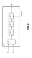
- Fig. 2 shows a heart monitor according to the invention (20), the part of the cardiac pacemaker (10) Fig. 1 can be.
- the heart monitor (20) has a signal input for receiving pressure or volume data or substitute quantities of a heart. These form an input signal of the heart monitor (20).
- the signal input can be connected to other components of the cardiac pacemaker (10) or directly with suitable measuring sensors, such as pressure or force sensors.
- the pacemaker is preferably designed, in a manner known per se, to determine a ventricular volume by means of an intraventricular impedance measurement.
- the impedance to be measured inside a ventricle of a heart is largely determined by the volume of blood trapped by the ventricle, because the blood has a higher conductivity than the surrounding heart tissue (myocardium).
- the measurements of the intracardiac and in particular the intraventricular impedance as well as the evaluation of the impedance curve for determining a ventricular volume are basically known and therefore need not be described in detail here.
- Measured variables which represent a pressure prevailing in the ventricle can be recorded, for example, by means of a pressure measuring sensor arranged in the ventricle. This can, as already indicated, be part of a ventricular electrode lead of the cardiac pacemaker (10).
- the pressure sensor can also be an independent sensor which is designed to transmit pressure measurement values wirelessly to the signal input of the heart monitor (20).
- the pressure measuring sensor can be passive, for example Type of transponder act. Other methods and sensors for determining the pressure prevailing in the ventricle are indicated at the beginning.
- the signal input (22) of the heart monitor (20) has two inputs in the exemplary embodiment shown here, namely an input for pressure readings or equivalent quantities and a second input for volume readings or equivalent quantities. This results in a two-channel input signal whose signal values are each formed by a pair of values of which one value represents a pressure measurement value and the other value represents a volume measurement value. The value pairs are numbered in chronological order.
- this signal input (22) of the heart monitor (20) is connected to an evaluation unit (24), which, as in Fig. 2 indicated, constructed in three stages.
- a first stage of the evaluation unit (24) is designed to segment the input signal consisting of signal value pairs such that each segment of the input signal reflects one cardiac cycle. This is done in the embodiment shown here in that the first stage (24.1) of the evaluation unit (24) is connected to a marker signal input, which is connected to a known marker channel of the cardiac pacemaker (10). Via the marker signal input (26), the first stage (24.1) of the evaluation unit (24) can receive marker signals representing the occurrence and the respective time of a cardiac event, for example an R-wave. Such marker signals are basically known and need not be explained in detail here.
- the first stage (24.1) of the evaluation unit (24) segments the input signal.
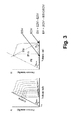
- Each segment of the input signal thus obtained represents a cardiac cycle and also represents a pV diagram representing the course of the pressure in the ventricle over the course of the volume in the ventricle. Exemplary diagrams are in Fig. 3 displayed.
- the evaluation unit (24) performs the analysis of the direction of rotation of the pV diagram represented by the signal value pairs described above by generating a two-dimensional coordinate system with an origin in the center of a pV diagram and for each signal value pair a vector from the center of the pV diagram Coordinate system to a respective signal value pair determined to determine the direction of rotation of successive signal value pairs. This should be monotonous in one direction. If individual pairs of signal pairs cause a reversal of the direction of rotation, these signal value pairs are eliminated or corrected (see page 3,17 - page 4,14).
- the evaluation unit (24) also has a second evaluation stage (24.2), which evaluates each segment of the input signal in the sense as described above by the second evaluation stage (24.2) of the evaluation unit (24) checks each segment of the input signal as to whether the respective segment of the input signal represents a pV diagram for which the derived quality features meet the quality criteria.
- the second evaluation stage (24.2) of the evaluation unit (24) is designed to compare a corrected input signal segment generated by it with the respective original segment of the input signal (morphology, area, ratio circumference to area, distance between start and end point or number of measured values ) and, depending on a respective comparison result, to decide whether the corrected pV diagram is suitable for further evaluation or not.
- the evaluation unit (24) and in particular its third evaluation stage (24.3) is finally connected to a control unit and / or at least one stimulation unit of the cardiac pacemaker (10) such that the evaluation unit (24) the delivery of stimulation pulses by the pacemaker (10) via the Can affect electrode lines.
- the cardiac pacemaker (10) acts as a cardiac stimulator and is designed to deliver electrical stimulation pulses via a cardiac stimulator in a manner known per se to the myocardium of a respective chamber (ventricle or atrium) of a heart Way to trigger a stimulated contraction of the respective heart chamber.
- ATD atrioventricular delay time
- VVD interventricular delay time
- the evaluation unit (24) is designed to vary the duration of a respective atrio-ventricular delay time and a respective interventricular delay time, in order first to determine the residual volume Vo, as required for determining the contractility index (Emax).
- the heart rate can be selectively modulated in order to realize a change in the filling state at the beginning of the systole and thus a preload variation.
- the evaluation unit (24) is designed to vary the atrioventricular delay time and / or the interventricular delay time and / or the pacing rate in order in this way to optimize the atrioventricular delay time and / or the interventricular delay time and / or the pacing rate Determine sizes for which there is a global optimum of the quantities derived from the third evaluation stage (24.3) from the pressure-volume diagram.
- the various components of the heart monitor (20) can be distributed to different physical entities, such as the pacemaker (10) and the external or patient device (12) or the central service center (14).
- the heart monitor (20) as a whole is part of the implantable cardiac pacemaker (10).
- the parameter values generated by the third evaluation stage (24.3) of the heart monitor (20) and derived from the input signal are also available at an output (28) of the third evaluation stage (24.3) of the evaluation unit (24).
- This output (28) is preferably connected to a memory and / or telemetry unit of the cardiac pacemaker (10) to provide the derived parameter values in this way telemetrically to the patient device (12) and from there on to the central service center (14) to transfer.
- the central service center (14) can then be designed to derive further values from the received derived parameter values, for example trends that reflect the development of the parameter values, and to provide or make available to a treating physician.
- the cardiac monitor (20) may be used to monitor, for example, the effectiveness of cardiac resynchronization therapy (CRT) or to better monitor long-term outcome using clinically-accepted parameters.
- CRT cardiac resynchronization therapy
Landscapes
- Health & Medical Sciences (AREA)
- Life Sciences & Earth Sciences (AREA)
- Cardiology (AREA)
- Heart & Thoracic Surgery (AREA)
- Engineering & Computer Science (AREA)
- Veterinary Medicine (AREA)
- Biomedical Technology (AREA)
- Animal Behavior & Ethology (AREA)
- General Health & Medical Sciences (AREA)
- Public Health (AREA)
- Biophysics (AREA)
- Nuclear Medicine, Radiotherapy & Molecular Imaging (AREA)
- Radiology & Medical Imaging (AREA)
- Physiology (AREA)
- Physics & Mathematics (AREA)
- Pathology (AREA)
- Medical Informatics (AREA)
- Molecular Biology (AREA)
- Surgery (AREA)
- Hospice & Palliative Care (AREA)
- Vascular Medicine (AREA)
- Electrotherapy Devices (AREA)
- Measuring Pulse, Heart Rate, Blood Pressure Or Blood Flow (AREA)
Claims (12)
- Moniteur cardiaque relié ou destiné à être relié à au moins un capteur pour des données de pression ou de volume ou des valeurs de remplacement d'un coeur, et comportant une unité d'évaluation pour le traitement des signaux d'entrée reflétant l'évolution dans le temps de données de pression et de volume ou de valeurs de remplacement du coeur, conçue de telle façon que l'unité d'évaluation effectue une segmentation des signaux d'entrée en fonction de cycles cardiaques individuels terminés, et vérifie ensuite respectivement les segments de signaux d'entrée ainsi obtenus pour savoir si un segment respectif des signaux d'entrée représente un diagramme pV correspondant à des conditions qualitatives prédéfinies, l'unité d'évaluation étant conçue pour évaluer des paires de valeurs de signal consécutives des signaux d'entrée quant à une direction périphérique d'un diagramme pV représenté par les paires de valeurs de signal, caractérisé en ce que l'unité d'évaluation est conçue pour utiliser la direction périphérique d'un diagramme pV respectif représenté par des paires de valeurs de signal pour reconnaître des paires de valeurs de signal invalides et éventuellement les corriger, afin d'établir un diagramme pV corrigé.
- Moniteur cardiaque selon la revendication 1, caractérisé en ce que l'unité d'évaluation est conçue pour déterminer une direction périphérique d'un diagramme pV respectivement représenté par les paires de valeurs de signal, par l'évaluation de la direction de vecteurs bidimensionnels, en générant un point central d'un système de coordonnées bidimensionnel avec une origine au centre d'un diagramme pV respectif et en déterminant, pour chaque paire de valeurs de signal, un vecteur allant du point central du système de coordonnées jusqu'à une paire de valeurs de signal respective, afin de déterminer la direction périphérique de paires de valeurs de signal consécutives.
- Moniteur cardiaque selon la revendication 1, caractérisé en ce que l'unité d'évaluation est conçue pour rejeter des paires de valeurs de signal présentant une direction périphérique différente, afin d'établir un diagramme pV corrigé.
- Moniteur cardiaque selon l'une des revendications 1 à 3, avec une entrée de signaux de marquage pour des signaux de marquage représentant des évènements définis au cours d'un cycle cardiaque respectif, y compris le moment de leur occurrence, caractérisé en ce que l'unité d'évaluation est conçue pour effectuer une segmentation des signaux d'entrée à l'aide de signaux de marquage à recevoir par le biais de l'entrée de signaux de marquage.
- Moniteur cardiaque selon l'une des revendications 1 à 3, caractérisé en ce que l'unité d'évaluation est conçue pour effectuer une segmentation des signaux d'entrée à l'aide de caractéristiques morphologiques des diagrammes pV représentés par les paires de valeurs de signal du signal d'entrée, et/ou pour effectuer une approximation des diagramme pV représentés par les paires de valeurs de signal, par des fonctions de remplacement telles que par exemple des ellipses, un rectangle, un trapèze, afin d'obtenir un diagramme pV corrigé, et/ou pour reconnaître automatiquement et corriger des points de croisement entre les diagrammes pV représentés par les paires de valeurs de signal qui sont issus de l'assemblage de paires de valeurs de signal consécutives, afin d'établir un diagramme pV corrigé, et/ou pour établir un diagramme pV corrigé en calculant une enveloppe incluant toutes les paires de valeurs de signal, et/ou pour approximer une suite de paires de valeurs de signal représentant un diagramme pV respectif par une ou plusieurs fonctions à paramètres optimisés, afin d'obtenir un diagramme pV corrigé.
- Moniteur cardiaque selon l'une des revendications 1 à 3, avec une entrée de signal d'ECG pour un signal d'ECG intracardiaque ou de surface, caractérisé en ce que l'unité d'évaluation est conçue pour effectuer une segmentation des signaux d'entrée à l'aide d'un signal d'ECG intracardiaque à recevoir par le biais de l'entrée de signal d'ECG.
- Moniteur cardiaque selon la revendication 5, caractérisé en ce que l'unité d'évaluation est conçue pour déterminer respectivement une enveloppe la plus grande possible n'incluant aucune paire de valeurs de signal d'un segment de signal représentant un diagramme pV respectif, ou pour déterminer l'enveloppe la plus petite possible incluant la plupart des paires de valeurs de signal d'un segment de signal représentant un diagramme pV respectif.
- Moniteur cardiaque selon l'une des revendications 1, 5 ou 7, caractérisé en ce que l'unité d'évaluation est conçue pour comparer des diagrammes pV corrigés avec le diagramme pV initial non corrigé correspondant, avant une nouvelle évaluation.
- Moniteur cardiaque selon la revendication 8, caractérisé en ce que l'unité d'évaluation est conçue pour effectuer la comparaison à l'aide de critères qualitatifs, tels que par exemple le nombre de paires de valeurs de signal corrigées ou rejetées, des différences dans la morphologie, la différence de surface, le rapport entre le pourtour et la surface, le décalage de point de gravité, la distance entre le point final et le point de départ ou autres, et pour décider si un diagramme pV corrigé respectif est prêt ou non pour une nouvelle évaluation, en fonction d'un résultat de comparaison respectif.
- Moniteur cardiaque selon l'une des revendications 1 à 9, caractérisé en ce que l'unité d'évaluation est conçue pour dériver une valeur pour un ou plusieurs des paramètres suivants ou similaires, dans le cadre d'une nouvelle évaluation, à partir d'un diagramme pV respectif représenté par des paires de valeurs de signal :- l'indice de contractilité (Emax)- le volume diastolique final (EDV)- le volume systolique final (ESV)- le volume de battement (SV)- la fraction d'éjection (EF = SV/EDV) ;- l'élastance artérielle effective (Ea)- le travail externe (EW)- l'énergie potentielle (PE)- la surface pression-volume (PVA)- le quotient du travail externe et de l'énergie potentielle (EW/PE)- le couplage artériel-ventriculaire (AVC = Ea/Emax)- la pression systolique finale (ESP)- le Preload-Recruitable-Stroke_Work (PRSW).
- Système constitué d'un moniteur cardiaque selon la revendication 10 et d'un stimulateur cardiaque reliés l'un à l'autre, caractérisé en ce que le moniteur cardiaque est conçu pour influencer la délivrance d'impulsions de stimulation par le stimulateur cardiaque :- dans lequel l'unité d'évaluation est conçue pour stimuler, dans le cadre de la nouvelle évaluation, des modifications locales du niveau de remplissage ou de l'indice de contractilité (Emax) par une modification de paramètres de stimulation, tels que la temporisation auriculo-ventriculaire (AVD) la temporisation inter-ventriculaire (VVD), la durée du cycle cardiaque ou autres, afin de pouvoir déterminer un volume résiduel respectif, ou- dans lequel l'unité d'évaluation est conçue pour utiliser l'une des valeurs dérivées pour l'optimisation simultanée d'une temporisation auriculo-ventriculaire (AVD) et/ou d'une temporisation inter-ventriculaire (VVD) et/ou de la fréquence de stimulation, en modifiant la temporisation auriculo-ventriculaire (AVD) et/ou la temporisation inter-ventriculaire (VVD) et/ou la fréquence de stimulation jusqu'à ce qu'un optimum global d'un ou de plusieurs paramètres dérivés soit atteint.
- Moniteur cardiaque selon la revendication 10, caractérisé en ce que l'unité d'évaluation est conçu pour utiliser, dans le cadre de la nouvelle évaluation, une reconnaissance automatique de modifications transitoires de l'indice de contractilité (Emax), de la pré-charge ou de la post-charge, pour l'actualisation d'une valeur respective du volume résiduel Vo.
Applications Claiming Priority (1)
| Application Number | Priority Date | Filing Date | Title |
|---|---|---|---|
| DE102009002397A DE102009002397A1 (de) | 2009-04-15 | 2009-04-15 | Herzmonitor |
Publications (3)
| Publication Number | Publication Date |
|---|---|
| EP2241348A2 EP2241348A2 (fr) | 2010-10-20 |
| EP2241348A3 EP2241348A3 (fr) | 2010-11-24 |
| EP2241348B1 true EP2241348B1 (fr) | 2015-05-06 |
Family
ID=42321184
Family Applications (1)
| Application Number | Title | Priority Date | Filing Date |
|---|---|---|---|
| EP20100156625 Not-in-force EP2241348B1 (fr) | 2009-04-15 | 2010-03-16 | Dispositif de surveillance cardiaque |
Country Status (3)
| Country | Link |
|---|---|
| US (1) | US8521265B2 (fr) |
| EP (1) | EP2241348B1 (fr) |
| DE (1) | DE102009002397A1 (fr) |
Families Citing this family (15)
| Publication number | Priority date | Publication date | Assignee | Title |
|---|---|---|---|---|
| US8086315B2 (en) | 2004-02-12 | 2011-12-27 | Asap Medical, Inc. | Cardiac stimulation apparatus and method for the control of hypertension |
| US8165674B2 (en) | 2005-03-02 | 2012-04-24 | Backbeat Medical, Inc. | Methods and apparatus to increase secretion of endogenous naturetic hormones |
| US7869874B2 (en) | 2006-09-25 | 2011-01-11 | G&L Consulting, Llc | Methods and apparatus to stimulate heart atria |
| US8340763B2 (en) | 2008-09-08 | 2012-12-25 | Backbeat Medical, Inc. | Methods and apparatus to stimulate heart atria |
| EP2561811A1 (fr) | 2011-08-23 | 2013-02-27 | BIOTRONIK SE & Co. KG | Comparaison des contractions ventriculaires gauche et droite à l'aide d'un accéléromètre dans une artère proche du coeur |
| CN103377298B (zh) * | 2012-04-24 | 2016-08-03 | 富士通株式会社 | 选择参数的方法和装置 |
| US9008769B2 (en) | 2012-12-21 | 2015-04-14 | Backbeat Medical, Inc. | Methods and systems for lowering blood pressure through reduction of ventricle filling |
| US10342982B2 (en) * | 2015-09-11 | 2019-07-09 | Backbeat Medical, Inc. | Methods and systems for treating cardiac malfunction |
| US10485658B2 (en) | 2016-04-22 | 2019-11-26 | Backbeat Medical, Inc. | Methods and systems for controlling blood pressure |
| US10874860B2 (en) | 2016-07-20 | 2020-12-29 | Cardiac Pacemakers, Inc. | Method and system for determining a cardiac cycle pace time in accordance with metabolic demand in a leadless cardiac pacemaker system |
| US10478629B2 (en) | 2016-07-20 | 2019-11-19 | Cardiac Pacemakers, Inc. | Leadless cardiac pacemaker for generating cardiac pressure volume loop |
| US10918858B2 (en) | 2016-07-20 | 2021-02-16 | Cardiac Pacemakers, Inc. | Cardiac volume sensing via an implantable medical device in support of cardiac resynchronization therapy |
| WO2018017361A1 (fr) | 2016-07-20 | 2018-01-25 | Cardiac Pacemakers, Inc. | Procédé et système de détermination d'un temps de stimulation dans un système de pacemaker cardiaque sans fil |
| AU2017350759B2 (en) | 2016-10-27 | 2019-10-17 | Cardiac Pacemakers, Inc. | Implantable medical device with pressure sensor |
| EP3668592B1 (fr) | 2017-08-18 | 2021-11-17 | Cardiac Pacemakers, Inc. | Dispositif médical implantable avec capteur de pression |
Citations (1)
| Publication number | Priority date | Publication date | Assignee | Title |
|---|---|---|---|---|
| WO2006107922A2 (fr) * | 2005-04-04 | 2006-10-12 | The Trustees Of Columbia University In The City Of New York | Procedes d'optimisation de la stimulation biventriculaire, dispositifs et systemes utilises a cet effet |
Family Cites Families (9)
| Publication number | Priority date | Publication date | Assignee | Title |
|---|---|---|---|---|
| US5643327A (en) * | 1995-06-20 | 1997-07-01 | Pacesetter, Inc. | Pacemaker and method having optimized A-V delay by using the evoked depolarization potential as an indicia of cardiac output |
| IL115538A (en) * | 1995-10-06 | 2000-10-31 | Pyrotec Ltd | Method and system for determination of the pressure-volume relationship of the heart |
| ATE342752T1 (de) | 2002-04-03 | 2006-11-15 | Osypka Medical Gmbh | Apparat zur automatischen bestimmung von hämodynamisch optimalen herzstimulationsparameterwerten |
| DE10361143A1 (de) * | 2003-09-01 | 2005-03-24 | Biotronik Gmbh & Co. Kg | Intrakardiale Impedanzmessanordnung |
| EP1510173B1 (fr) | 2003-09-01 | 2017-04-05 | BIOTRONIK SE & Co. KG | Appareil de mesure d'impédances intracardiaques |
| US7286875B1 (en) | 2004-05-03 | 2007-10-23 | Pacesetter, Inc. | Monitoring ventricular contractions using an implantable stimulation device |
| US7363077B1 (en) * | 2004-11-09 | 2008-04-22 | Pacesetters, Inc. | Adaptive timing interval control method for treating congestive heart failure |
| WO2007022505A2 (fr) | 2005-08-19 | 2007-02-22 | Visualsonics Inc. | Systèmes et procédés de capture et d’affichage de la pression sanguine et de données par ultrasons |
| US7580746B2 (en) * | 2005-12-07 | 2009-08-25 | Cardiac Pacemakers, Inc. | Implantable medical device for generating cardiac pressure-volume loop and optimizing therapy |
-
2009
- 2009-04-15 DE DE102009002397A patent/DE102009002397A1/de not_active Withdrawn
-
2010
- 2010-03-16 EP EP20100156625 patent/EP2241348B1/fr not_active Not-in-force
- 2010-03-30 US US12/749,723 patent/US8521265B2/en not_active Expired - Fee Related
Patent Citations (1)
| Publication number | Priority date | Publication date | Assignee | Title |
|---|---|---|---|---|
| WO2006107922A2 (fr) * | 2005-04-04 | 2006-10-12 | The Trustees Of Columbia University In The City Of New York | Procedes d'optimisation de la stimulation biventriculaire, dispositifs et systemes utilises a cet effet |
Also Published As
| Publication number | Publication date |
|---|---|
| US20100268294A1 (en) | 2010-10-21 |
| US8521265B2 (en) | 2013-08-27 |
| EP2241348A2 (fr) | 2010-10-20 |
| EP2241348A3 (fr) | 2010-11-24 |
| DE102009002397A1 (de) | 2010-10-21 |
Similar Documents
| Publication | Publication Date | Title |
|---|---|---|
| EP2241348B1 (fr) | Dispositif de surveillance cardiaque | |
| EP2433565B1 (fr) | Appareil médical implantable | |
| EP2060299B1 (fr) | Stimulateur cardiaque bi-ventriculaire | |
| DE69929448T2 (de) | Implantierbarer sensor mit drahtloser kommunikation | |
| EP1510173B1 (fr) | Appareil de mesure d'impédances intracardiaques | |
| EP1586348B1 (fr) | Dispositif d'électrothérapie | |
| DE69313215T2 (de) | Verfahren und Vorrichtung zur Überwachung der Herzfunktion | |
| DE602004006105T2 (de) | Vorrichtung zur auswertung und optimierung ventrikulärer synchronisation | |
| DE60118433T2 (de) | Implantierbare medizinische vorrichtung zur überwachung von kongestiver herzinsuffizienz | |
| DE69926502T2 (de) | Herzreizung unter verwendung von einstellbaren atrio-ventrikulären verzögerungsintervallen | |
| DE69426323T2 (de) | Vorrichtung und Verfahren zur Bestimmung vom Herzmuskelfunktionszustand | |
| DE60106645T2 (de) | Apparat zur messung des mittleren blutdruckes in der lungenarterie von der herzkammer aus mit einem mobilen überwachungsgerät | |
| DE60132016T2 (de) | Implantierbare medizinische einrichtung zur behandlung von mechanischen herzfunktionsstörungen mittels elektrischer stimulation | |
| DE69213657T2 (de) | Implantierbares Gerät zur Überwachung und Stimulation des Herzens für Diagnose und Therapie | |
| EP2968916B1 (fr) | Dispositif médical ayant une fusion à capteurs multiples | |
| DE60221186T2 (de) | Zweikammer-Herzschrittmachersystem mit einer dynamisch angepassten Interpulse-Verzögerung | |
| EP1762270B1 (fr) | Dispositif pour la détermination des paramètres cardiaques | |
| DE60131041T2 (de) | Implantierbare Herzvorrichtung zur Überwachung der Verschlechterung oder Verbesserung von Herzerkrankungen | |
| DE10119394A1 (de) | Schrittmachen mit geregeltem Koronarsinusfluß | |
| DE60216970T2 (de) | Implantierbare herzstimulationsvorrichtung sowie diese vorrichtung enthaltendes system | |
| DE602004012899T2 (de) | Nachweis und/oder überwachung von diastolischer herzinsuffizienz | |
| EP2561811A1 (fr) | Comparaison des contractions ventriculaires gauche et droite à l'aide d'un accéléromètre dans une artère proche du coeur | |
| DE102007057227B4 (de) | Herzstimulationsanordnung | |
| EP2422843B1 (fr) | Appareil de thérapie électronique implantable | |
| EP2279775B1 (fr) | Stimulateur cardiaque pour stimuler un ventricule en réponse à un événement ventriculaire controlatéral détécté |
Legal Events
| Date | Code | Title | Description |
|---|---|---|---|
| PUAI | Public reference made under article 153(3) epc to a published international application that has entered the european phase |
Free format text: ORIGINAL CODE: 0009012 |
|
| AK | Designated contracting states |
Kind code of ref document: A2 Designated state(s): AT BE BG CH CY CZ DE DK EE ES FI FR GB GR HR HU IE IS IT LI LT LU LV MC MK MT NL NO PL PT RO SE SI SK SM TR |
|
| AX | Request for extension of the european patent |
Extension state: AL BA ME RS |
|
| PUAL | Search report despatched |
Free format text: ORIGINAL CODE: 0009013 |
|
| AK | Designated contracting states |
Kind code of ref document: A3 Designated state(s): AT BE BG CH CY CZ DE DK EE ES FI FR GB GR HR HU IE IS IT LI LT LU LV MC MK MT NL NO PL PT RO SE SI SK SM TR |
|
| AX | Request for extension of the european patent |
Extension state: AL BA ME RS |
|
| 17P | Request for examination filed |
Effective date: 20110502 |
|
| 17Q | First examination report despatched |
Effective date: 20130523 |
|
| RIC1 | Information provided on ipc code assigned before grant |
Ipc: A61B 5/0215 20060101ALI20141217BHEP Ipc: A61N 1/362 20060101ALI20141217BHEP Ipc: A61B 5/053 20060101ALI20141217BHEP Ipc: A61B 5/107 20060101ALN20141217BHEP Ipc: A61N 1/365 20060101AFI20141217BHEP |
|
| GRAP | Despatch of communication of intention to grant a patent |
Free format text: ORIGINAL CODE: EPIDOSNIGR1 |
|
| INTG | Intention to grant announced |
Effective date: 20150203 |
|
| RIN1 | Information on inventor provided before grant (corrected) |
Inventor name: CZYGAN, GERALD Inventor name: SKERL, OLAF Inventor name: KRAEMER, THOMAS Inventor name: LIPPERT, MICHAEL Inventor name: VOLLKRON, MICHAEL |
|
| GRAS | Grant fee paid |
Free format text: ORIGINAL CODE: EPIDOSNIGR3 |
|
| GRAA | (expected) grant |
Free format text: ORIGINAL CODE: 0009210 |
|
| AK | Designated contracting states |
Kind code of ref document: B1 Designated state(s): AT BE BG CH CY CZ DE DK EE ES FI FR GB GR HR HU IE IS IT LI LT LU LV MC MK MT NL NO PL PT RO SE SI SK SM TR |
|
| REG | Reference to a national code |
Ref country code: GB Ref legal event code: FG4D Free format text: NOT ENGLISH |
|
| REG | Reference to a national code |
Ref country code: CH Ref legal event code: EP |
|
| REG | Reference to a national code |
Ref country code: IE Ref legal event code: FG4D Free format text: LANGUAGE OF EP DOCUMENT: GERMAN |
|
| REG | Reference to a national code |
Ref country code: AT Ref legal event code: REF Ref document number: 725274 Country of ref document: AT Kind code of ref document: T Effective date: 20150615 |
|
| REG | Reference to a national code |
Ref country code: DE Ref legal event code: R096 Ref document number: 502010009467 Country of ref document: DE Effective date: 20150618 |
|
| REG | Reference to a national code |
Ref country code: DE Ref legal event code: R082 Country of ref document: DE Ref country code: DE Ref legal event code: R082 Ref document number: 502010009467 Country of ref document: DE Representative=s name: RANDOLL, SOEREN, DIPL.-CHEM. UNIV. DR. RER. NA, DE |
|
| REG | Reference to a national code |
Ref country code: NL Ref legal event code: MP Effective date: 20150506 |
|
| REG | Reference to a national code |
Ref country code: LT Ref legal event code: MG4D |
|
| PG25 | Lapsed in a contracting state [announced via postgrant information from national office to epo] |
Ref country code: LT Free format text: LAPSE BECAUSE OF FAILURE TO SUBMIT A TRANSLATION OF THE DESCRIPTION OR TO PAY THE FEE WITHIN THE PRESCRIBED TIME-LIMIT Effective date: 20150506 Ref country code: ES Free format text: LAPSE BECAUSE OF FAILURE TO SUBMIT A TRANSLATION OF THE DESCRIPTION OR TO PAY THE FEE WITHIN THE PRESCRIBED TIME-LIMIT Effective date: 20150506 Ref country code: NO Free format text: LAPSE BECAUSE OF FAILURE TO SUBMIT A TRANSLATION OF THE DESCRIPTION OR TO PAY THE FEE WITHIN THE PRESCRIBED TIME-LIMIT Effective date: 20150806 Ref country code: FI Free format text: LAPSE BECAUSE OF FAILURE TO SUBMIT A TRANSLATION OF THE DESCRIPTION OR TO PAY THE FEE WITHIN THE PRESCRIBED TIME-LIMIT Effective date: 20150506 Ref country code: HR Free format text: LAPSE BECAUSE OF FAILURE TO SUBMIT A TRANSLATION OF THE DESCRIPTION OR TO PAY THE FEE WITHIN THE PRESCRIBED TIME-LIMIT Effective date: 20150506 Ref country code: PT Free format text: LAPSE BECAUSE OF FAILURE TO SUBMIT A TRANSLATION OF THE DESCRIPTION OR TO PAY THE FEE WITHIN THE PRESCRIBED TIME-LIMIT Effective date: 20150907 |
|
| PG25 | Lapsed in a contracting state [announced via postgrant information from national office to epo] |
Ref country code: GR Free format text: LAPSE BECAUSE OF FAILURE TO SUBMIT A TRANSLATION OF THE DESCRIPTION OR TO PAY THE FEE WITHIN THE PRESCRIBED TIME-LIMIT Effective date: 20150807 Ref country code: BG Free format text: LAPSE BECAUSE OF FAILURE TO SUBMIT A TRANSLATION OF THE DESCRIPTION OR TO PAY THE FEE WITHIN THE PRESCRIBED TIME-LIMIT Effective date: 20150806 Ref country code: LV Free format text: LAPSE BECAUSE OF FAILURE TO SUBMIT A TRANSLATION OF THE DESCRIPTION OR TO PAY THE FEE WITHIN THE PRESCRIBED TIME-LIMIT Effective date: 20150506 Ref country code: IS Free format text: LAPSE BECAUSE OF FAILURE TO SUBMIT A TRANSLATION OF THE DESCRIPTION OR TO PAY THE FEE WITHIN THE PRESCRIBED TIME-LIMIT Effective date: 20150906 |
|
| PG25 | Lapsed in a contracting state [announced via postgrant information from national office to epo] |
Ref country code: DK Free format text: LAPSE BECAUSE OF FAILURE TO SUBMIT A TRANSLATION OF THE DESCRIPTION OR TO PAY THE FEE WITHIN THE PRESCRIBED TIME-LIMIT Effective date: 20150506 Ref country code: EE Free format text: LAPSE BECAUSE OF FAILURE TO SUBMIT A TRANSLATION OF THE DESCRIPTION OR TO PAY THE FEE WITHIN THE PRESCRIBED TIME-LIMIT Effective date: 20150506 |
|
| REG | Reference to a national code |
Ref country code: DE Ref legal event code: R097 Ref document number: 502010009467 Country of ref document: DE |
|
| PG25 | Lapsed in a contracting state [announced via postgrant information from national office to epo] |
Ref country code: PL Free format text: LAPSE BECAUSE OF FAILURE TO SUBMIT A TRANSLATION OF THE DESCRIPTION OR TO PAY THE FEE WITHIN THE PRESCRIBED TIME-LIMIT Effective date: 20150506 Ref country code: SK Free format text: LAPSE BECAUSE OF FAILURE TO SUBMIT A TRANSLATION OF THE DESCRIPTION OR TO PAY THE FEE WITHIN THE PRESCRIBED TIME-LIMIT Effective date: 20150506 Ref country code: RO Free format text: LAPSE BECAUSE OF NON-PAYMENT OF DUE FEES Effective date: 20150506 Ref country code: CZ Free format text: LAPSE BECAUSE OF FAILURE TO SUBMIT A TRANSLATION OF THE DESCRIPTION OR TO PAY THE FEE WITHIN THE PRESCRIBED TIME-LIMIT Effective date: 20150506 |
|
| PLBE | No opposition filed within time limit |
Free format text: ORIGINAL CODE: 0009261 |
|
| STAA | Information on the status of an ep patent application or granted ep patent |
Free format text: STATUS: NO OPPOSITION FILED WITHIN TIME LIMIT |
|
| 26N | No opposition filed |
Effective date: 20160209 |
|
| PG25 | Lapsed in a contracting state [announced via postgrant information from national office to epo] |
Ref country code: IT Free format text: LAPSE BECAUSE OF FAILURE TO SUBMIT A TRANSLATION OF THE DESCRIPTION OR TO PAY THE FEE WITHIN THE PRESCRIBED TIME-LIMIT Effective date: 20150506 |
|
| PG25 | Lapsed in a contracting state [announced via postgrant information from national office to epo] |
Ref country code: SI Free format text: LAPSE BECAUSE OF FAILURE TO SUBMIT A TRANSLATION OF THE DESCRIPTION OR TO PAY THE FEE WITHIN THE PRESCRIBED TIME-LIMIT Effective date: 20150506 |
|
| PG25 | Lapsed in a contracting state [announced via postgrant information from national office to epo] |
Ref country code: BE Free format text: LAPSE BECAUSE OF NON-PAYMENT OF DUE FEES Effective date: 20160331 |
|
| PG25 | Lapsed in a contracting state [announced via postgrant information from national office to epo] |
Ref country code: LU Free format text: LAPSE BECAUSE OF FAILURE TO SUBMIT A TRANSLATION OF THE DESCRIPTION OR TO PAY THE FEE WITHIN THE PRESCRIBED TIME-LIMIT Effective date: 20160316 Ref country code: MC Free format text: LAPSE BECAUSE OF FAILURE TO SUBMIT A TRANSLATION OF THE DESCRIPTION OR TO PAY THE FEE WITHIN THE PRESCRIBED TIME-LIMIT Effective date: 20150506 |
|
| GBPC | Gb: european patent ceased through non-payment of renewal fee |
Effective date: 20160316 |
|
| REG | Reference to a national code |
Ref country code: FR Ref legal event code: ST Effective date: 20161130 |
|
| PG25 | Lapsed in a contracting state [announced via postgrant information from national office to epo] |
Ref country code: GB Free format text: LAPSE BECAUSE OF NON-PAYMENT OF DUE FEES Effective date: 20160316 Ref country code: FR Free format text: LAPSE BECAUSE OF NON-PAYMENT OF DUE FEES Effective date: 20160331 |
|
| REG | Reference to a national code |
Ref country code: AT Ref legal event code: MM01 Ref document number: 725274 Country of ref document: AT Kind code of ref document: T Effective date: 20160316 |
|
| PG25 | Lapsed in a contracting state [announced via postgrant information from national office to epo] |
Ref country code: SE Free format text: LAPSE BECAUSE OF FAILURE TO SUBMIT A TRANSLATION OF THE DESCRIPTION OR TO PAY THE FEE WITHIN THE PRESCRIBED TIME-LIMIT Effective date: 20150506 Ref country code: NL Free format text: LAPSE BECAUSE OF FAILURE TO SUBMIT A TRANSLATION OF THE DESCRIPTION OR TO PAY THE FEE WITHIN THE PRESCRIBED TIME-LIMIT Effective date: 20150506 |
|
| PG25 | Lapsed in a contracting state [announced via postgrant information from national office to epo] |
Ref country code: MT Free format text: LAPSE BECAUSE OF FAILURE TO SUBMIT A TRANSLATION OF THE DESCRIPTION OR TO PAY THE FEE WITHIN THE PRESCRIBED TIME-LIMIT Effective date: 20150506 Ref country code: AT Free format text: LAPSE BECAUSE OF NON-PAYMENT OF DUE FEES Effective date: 20160316 |
|
| REG | Reference to a national code |
Ref country code: DE Ref legal event code: R082 Ref document number: 502010009467 Country of ref document: DE Ref country code: DE Ref legal event code: R081 Ref document number: 502010009467 Country of ref document: DE Owner name: BIOTRONIK SE & CO. KG, DE Free format text: FORMER OWNER: BIOTRONIK CRM PATENT AG, BAAR, CH |
|
| PG25 | Lapsed in a contracting state [announced via postgrant information from national office to epo] |
Ref country code: HU Free format text: LAPSE BECAUSE OF FAILURE TO SUBMIT A TRANSLATION OF THE DESCRIPTION OR TO PAY THE FEE WITHIN THE PRESCRIBED TIME-LIMIT; INVALID AB INITIO Effective date: 20100316 Ref country code: CY Free format text: LAPSE BECAUSE OF FAILURE TO SUBMIT A TRANSLATION OF THE DESCRIPTION OR TO PAY THE FEE WITHIN THE PRESCRIBED TIME-LIMIT Effective date: 20150506 Ref country code: SM Free format text: LAPSE BECAUSE OF FAILURE TO SUBMIT A TRANSLATION OF THE DESCRIPTION OR TO PAY THE FEE WITHIN THE PRESCRIBED TIME-LIMIT Effective date: 20150506 |
|
| PG25 | Lapsed in a contracting state [announced via postgrant information from national office to epo] |
Ref country code: TR Free format text: LAPSE BECAUSE OF FAILURE TO SUBMIT A TRANSLATION OF THE DESCRIPTION OR TO PAY THE FEE WITHIN THE PRESCRIBED TIME-LIMIT Effective date: 20150506 Ref country code: MK Free format text: LAPSE BECAUSE OF FAILURE TO SUBMIT A TRANSLATION OF THE DESCRIPTION OR TO PAY THE FEE WITHIN THE PRESCRIBED TIME-LIMIT Effective date: 20150506 |
|
| PGFP | Annual fee paid to national office [announced via postgrant information from national office to epo] |
Ref country code: IE Payment date: 20220322 Year of fee payment: 13 Ref country code: DE Payment date: 20220317 Year of fee payment: 13 Ref country code: CH Payment date: 20220324 Year of fee payment: 13 |
|
| REG | Reference to a national code |
Ref country code: DE Ref legal event code: R119 Ref document number: 502010009467 Country of ref document: DE |
|
| REG | Reference to a national code |
Ref country code: CH Ref legal event code: PL |
|
| REG | Reference to a national code |
Ref country code: IE Ref legal event code: MM4A |
|
| PG25 | Lapsed in a contracting state [announced via postgrant information from national office to epo] |
Ref country code: LI Free format text: LAPSE BECAUSE OF NON-PAYMENT OF DUE FEES Effective date: 20230331 Ref country code: IE Free format text: LAPSE BECAUSE OF NON-PAYMENT OF DUE FEES Effective date: 20230316 Ref country code: DE Free format text: LAPSE BECAUSE OF NON-PAYMENT OF DUE FEES Effective date: 20231003 Ref country code: CH Free format text: LAPSE BECAUSE OF NON-PAYMENT OF DUE FEES Effective date: 20230331 |