EP2241396A2 - Machine-outil, notamment scie à onglet, ainsi qu'indicateur de ligne de coupe laser pour une machine-outil - Google Patents
Machine-outil, notamment scie à onglet, ainsi qu'indicateur de ligne de coupe laser pour une machine-outil Download PDFInfo
- Publication number
- EP2241396A2 EP2241396A2 EP20100002001 EP10002001A EP2241396A2 EP 2241396 A2 EP2241396 A2 EP 2241396A2 EP 20100002001 EP20100002001 EP 20100002001 EP 10002001 A EP10002001 A EP 10002001A EP 2241396 A2 EP2241396 A2 EP 2241396A2
- Authority
- EP
- European Patent Office
- Prior art keywords
- support frame
- machine tool
- laser
- saw
- guide
- Prior art date
- Legal status (The legal status is an assumption and is not a legal conclusion. Google has not performed a legal analysis and makes no representation as to the accuracy of the status listed.)
- Granted
Links
Images




Classifications
-
- B—PERFORMING OPERATIONS; TRANSPORTING
- B23—MACHINE TOOLS; METAL-WORKING NOT OTHERWISE PROVIDED FOR
- B23D—PLANING; SLOTTING; SHEARING; BROACHING; SAWING; FILING; SCRAPING; LIKE OPERATIONS FOR WORKING METAL BY REMOVING MATERIAL, NOT OTHERWISE PROVIDED FOR
- B23D59/00—Accessories specially designed for sawing machines or sawing devices
- B23D59/001—Measuring or control devices, e.g. for automatic control of work feed pressure on band saw blade
- B23D59/002—Measuring or control devices, e.g. for automatic control of work feed pressure on band saw blade for the position of the saw blade
- B23D59/003—Indicating the cutting plane on the workpiece, e.g. by projecting a laser beam
Definitions
- the invention relates firstly to a machine tool, in particular a chop saw, with the features of the preamble of claim 1, of claim 13 or of claim 14, on the other hand a laser cutting indicator with the features of the preamble of claim 7 or of claim 11.
- Machine tools of the type in question are machines for woodworking, metalworking or plastics processing.
- it is semi-stationary machine tools such as chop saws, but also to handheld devices such as circular saws or the like.
- a typical chop saw has a saw unit mounted pivotably about a transverse axis, the saw blade of which is pivotable from a raised rest position into a lowered saw position and vice versa. With this movement of the saw blade, a workpiece located on a workpiece support surface of a support can be cut off - cut off -.
- chop saws are known not only with a saw unit mounted pivotably about a transverse axis, but also with a saw unit which can be pulled over the workpiece support surface in the longitudinal direction as so-called radial saws.
- the saw unit of a chop saw is normally biased in the direction of the rest position. This is usually done by a spring arrangement, in older constructions even by a counterweight, Contrary to the biasing force, the saw unit is handled on an operating handle and pivoted down to execute the saw cut until the workpiece located on the workpiece support surface is completely severed. In this case, a small portion of the saw blade of the saw unit enters the edge in a submerged slot in the workpiece support surface.
- the known chop saw from which the invention proceeds ( US-A-2006/0042444 ), is a miter, miter and pull saw, which can be used for cross cuts, miter cuts and shear cuts (double miter cuts). Because of the also implemented as a radial arm saw traction, the executed cuts may be longer than the effective cutting radius of the saw blade pretends.
- the saw unit is mounted by means of a bracket on the carrier.
- Kappfunktion the saw unit is given to a transverse axis from the raised rest position in the lowered sawing and vice versa.
- a tilt adjustment is provided here, moreover.
- the tilt adjustment is used to pivot the saw unit relative to the carrier to a horizontal direction in the direction of sawing pivot axis, just to perform a miter cut at the desired miter angle can.
- the laser unit of the laser cut indicator must be adjusted precisely to the saw cut plane of the saw blade (or the tool working plane of the tool).
- the laser cutting indicator is arranged directly in the fixed protective cover for the saw blade.
- the protective hood with its side walls forms a receiving space for the laser cut indicator arranged and fastened therein.
- a displacement axis in the receiving space is arranged between the side walls of the guard exactly across the shegeschnittebene.
- a support frame in a first degree of freedom is linearly adjustable transversely to the shegeschnittebene.
- the support frame itself carries the laser unit, which is adjustable in several degrees of freedom.
- the laser unit in the support frame serve several adjustment means, each having a screw and a biasing spring.
- the biasing spring By the biasing spring, the respective system is biased in one direction, thereby the system is set backlash.
- By adjusting the screw with simultaneously acting biasing spring adjustment takes place in the various degrees of freedom.
- the actuation of the adjusting means takes place from different directions.
- the points of attack of the various adjusting means lie on different components of the protective hood and the support frame.
- the guidance of various components on guide axes leads to stiction. Due to the many different components of the support frame manufacturing tolerances arise that complicate a backlash-free setting. It should be noted that the environmental conditions for a machine tool of the type in question are difficult (dust, moisture).
- the laser cutting indicator is also installed in the fixed guard. There, too, there are corresponding adjustment difficulties ( US-A-2003/0233921 ).
- the invention is therefore based on the problem of optimizing the known, initially explained machine tool, from which the invention proceeds, with regard to the attachment of the laser cutting indicator.
- Object of the present invention is also the indication of a laser cutting indicator with optimized design and adjustability.
- the laser unit of the laser cut indicator normally generates a line mark on a workpiece to be machined, this line mark indicating the position of the saw cut in the workpiece.
- the arrangement of the support frame of the laser cutting indicator on a sliding axis for various reasons is problematic, a very useful construction is realized in the machine tool according to the invention with the dome-like guide for the web on the support frame.
- the fixed guard usually made of aluminum, has a high manufacturing accuracy.
- the dome-like guide allows a dimensionally stable mounting of the support frame for the laser-cut indicator so that this support frame can be adjusted linearly transversely to the shege4.000ebene in a first degree of freedom,
- the laser unit can the side of the tool, in particular the saw blade of a chop saw approach.
- the invention is also a laser cutting indicator as such according to the preamble of claim 7, which is characterized by the features of the characterizing part of claim 7.
- the problem is also solved in a laser cutting indicator with the features of the preamble of claim 9 by the features of the characterizing part of claim 9.
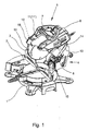
- Fig. 1 shows a chop saw, more precisely a miter, miter and pull saw.
- teachings of the present invention are generally applicable to all types of machine tools with corresponding laser cut indicators, especially hand-held devices such as circular saws, jigsaws or the like.
- the chop saw shown initially has a carrier 1, which forms a workpiece support surface 2.
- the rear end of the workpiece support surface 2 here forms a stop rail 3, on which a workpiece, for example a wooden strip; can be created.
- a holder 4 is mounted, which lies behind the back of the workpiece support surface 2.
- a saw unit 5 Attached to the holder 4 above the carrier 1 is a saw unit 5. In the illustrated embodiment, this is pivotable about a transverse axis 6 and is located above the workpiece support surface 2.
- the transverse axis would be omitted.
- the saw unit would be pulled here on tie rods that cantilever over the workpiece support surface.
- the saw unit 5 is about the transverse axis 6 from a raised rest position, the in Fig. 1 can be seen, in a lowered sawing, which is not shown here, and pivoted vice versa, the saw unit 5 is biased in the direction of the rest position, ie upwards, in particular by a spring. As a result, the saw unit 5, when you let go, returns by itself back to the raised rest position.
- the chop saw shown has a miter function in addition to the previously described Kappfunktion. So it's already a crosscut and miter saw.
- the chop saw has a tilt adjustment 15 with which the saw unit 5 can be pivoted relative to the carrier 1 about a horizontal tilt pivot axis. This can physically or even geometrically, for example, replaced by a backdrop-like design, be present.
- a chop saw of the type in question can also have a pull function in addition to a cap function and a miter function. Basically, may on the already mentioned at the beginning DE-U-203 13 885 to get expelled.
- the teaching of the invention also applies to a chop saw with traction.
- Fig. 1 can be seen now front left on the fixed guard 11 of the machine tool shown here as a cross-section saw example, a widening in which a receiving space 16 arranged and fastened therein, but in Fig. 1 not shown laser cutting indicator 17 is located. It is easy to imagine how the laser beam, fanned out in the saw-cut plane, extends down to the workpiece and marked there the position of the introduced saw cut on the workpiece.
- Fig. 2 shows a view from the bottom left in Fig. 1
- the two side walls 11 ', 11 "of the protective hood 11 can be seen, between which the receiving space 16 for the laser cut indicator 17 arranged and fastened therein is formed Fig. 2
- the laser cut indicator 17 has a support frame 18 and a laser unit 19 adjustable therein in several degrees of freedom.
- a significant adjustment direction of the laser unit 19 is the direction transverse to the shegeschnittebene.
- the laser unit 19 is first aligned correctly once on the shegesammlungebene. This is the first degree of freedom for the adjustment of the laser unit 19.
- the circular saw blade defines the shegeauerebene.
- Fig. 2 and Fig. 4 show in the context that the laser radiation of the laser unit 19 by adjustment of the support frame 18 in the receiving space 16 - in the first degree of freedom - linearly transversely to the shegesammlungebene - and by adjusting the laser unit 19 in the support frame 18 in further degrees of freedom on the shegesammlungebene be aligned.
- Fig. 2 and Fig. 3 in connection let now recognize the particular constructive conception of the teaching, which is that at least one dome-like, transversely to the polege4.000ebene to the other side wall 11 'directed towards 20 at least one side wall 11' of the protective hood 11 is arranged inside that the support frame 18th a in the guide 20 in register fit moving element, in particular a running therein web 21 is arranged and that by adjusting the web 21 in the guide 20 by means of a first adjustment means 22 of the support frame 18 in the first degree of freedom is linearly adjustable transversely to the saw sectional plane.
- the first adjustment means 22 is in Fig. 4 identified. It is used for adjustment in the first degree of freedom.
- the guide 20 is formed for the web 21 on the support frame 18 directly dome-like with high manufacturing accuracy.
- the web 21 can slide in the guide 20 first class. The adjustment in the first degree of freedom is optimized.
- the dome-like guide 20 has a lateral slot 23 and the web 21 engages through the slot 23 therethrough.
- the slot 23 can be seen in Fig. 3 especially good.
- the slot 23 allows the web 21 with the support frame 18 in the rest of a strip-like, elongated connection safely and rigid to connect.
- the first adjustment means 22 is covered by the dome-like guide 20 for the web 21.
- the dome-like guide 20 is omitted because the protective hood 11 is not shown at all.
- the first adjusting means 22 has a screw 24 mounted on one side wall, preferably on the other side wall 11 ', and preferably a biasing spring 25, wherein the screw 24 engages in a thread on the web 21.
- biasing spring 25 which is designed here as a helical compression spring, you can see a distance.
- the biasing spring 25 is so if you Fig. 4 viewed from the right inside on the side wall 11 'at. It is supported on the bridge 21 on the right.
- the screw 24 engages in a thread on the right of the web 21 a. This thread is hidden here.
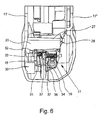
- FIG. 6 A particular structural embodiment of the invention can be made in this context Fig. 6 remove.
- Fig. 6 it can be seen above that the displacement of the support frame 18 away from the first side wall 11 'is limited and that, preferably, to the first side wall 11' to the guide 20 parallel support 27 with a mounted thereon Limit stop 28 is provided for the adjustment of the web 21 in the guide 20.
- the carrier 27 is integrally formed on the side wall 11 '. On this right sits as a limit stop 28, a snap ring, which prevents the web 21 is pushed out of the guide 20 to the right.
- Fig. 3 can be seen that in the illustrated embodiment, on the side wall 11 ', a second, laterally spaced from the first guide 20 dome-like guide 30 and the support frame 18, a second, in the second guide 30 in register running moving element, also here according to a preferred embodiment, a corresponding Bridge 31, are arranged.
- the further web 31 can be seen indicated for example in Fig. 6 Overall, this is a two-fold leadership of the support frame 18 linear transverse to the shegeismeebene.
- the second guide 30 is assigned but no further adjustment.
- the adjusting means 32, 33 are constructed exactly like the first adjusting means 22, namely with a screw and a biasing spring. Therefore, these parts have not been given their own reference signs. In any case, this form of adjustment, which is also realized in the prior art, expedient, because it is feasible from the backlash play.
- Fig. 4 shows a complete laser cut indicator 17 with its support frame 18 and the laser unit 19, which, however, still in a housing or otherwise realized receiving space 16, here just in the fixed guard 11, must be installed. It can be seen here in the support frame 18 a preferably made of plastic integrally formed support portion 34 for the bearing unit 19. The support portion 34 is in Fig. 4 suspended above the support frame 18. The second adjustment means 32, which in Fig. 4 can be seen on the left, pushes the support portion 34 against the spring force of the associated biasing spring 25, which in Fig. 4 is to recognize right, wherein the plastic material of the support portion 34 deforms slightly at the bottleneck near the suspension.
- laser cut indicator 17 in total can be arranged in a separate, self-sufficient housing. He would then be attached as an attachment to a machine tool. This will be discussed later.
- self-sufficient laser cut indicator 17 apply in principle the same considerations that have been previously presented.
- the support frame has various mutually adjustable sections 34, 36 which are connected to one another via deformable intermediate regions 37, in particular in the form of predetermined bending points, film hinges or the like, and that an adjusting means 32, 33 in each case two over at least one intermediate region 37 interconnected portions 18, 34, 34, 36 interconnects or adjusted to each other.
- the first section in a sense the fixed base section, is the support frame 18 as such. Therefore, this base section has in Fig. 5 also the reference numeral 18. This base portion is made in one piece with the web 21 of the support frame 18, the in Fig. 5 is guided in the top of the guide 20 linear.
- the second adjustment means 32 again with screw and biasing spring. This is located between the base portion of the support frame 18 and a contrast adjustable portion 34. This has previously been referred to as a support portion 34.
- the thread for the screw of the second adjusting means 32 is here in the support portion 34.
- the socket on the base portion of the support frame 18 serves as an abutment 35 for the second adjustment means 32nd
- the deformable intermediate region 37 is designed here as a film hinge or as a predetermined bending point.
- the base portion of the support frame 18 and the support portion 34 are thus integrally formed with each other, including the intermediate portion 37th
- the support portion 34 On the support portion 34 is in turn integrally connected via an intermediate portion 37 in the form of a film hinge another section 36, also referred to as a holding portion 36.
- the third adjustment means 33 turn with screw and biasing spring, in which case the abutment is formed by the support portion 34 and the thread for the screw is right in the holding portion 36 (see also Fig. 6 ).
- the support frame 18, preferably in one piece and preferably made of plastic is produced in a production molding process.
- a one-piece production by injection molding of a thermoplastic, optionally fiber-reinforced plastic will recommend.
- Fig. 5 and 6 illustrated embodiment is further characterized in that the support frame 18 has a laser unit 19 carrying portion 36 which is pivotable about an asymmetrically arranged intermediate portion 37 or quasi-pivotable.
- Fig. 5 shows the linear adjustment in the first degree of freedom by means of the first adjustment means 22.
- the support frame 18 guided by the first guide 20 and the second guide 30, the support frame 18 as a whole right / left adjusted. This adjusts the fanned laser radiation laterally relative to the saw blade 10.
- Fig. 5 and 6 is also the tilting movement of the support portion 34 relative to the base portion of the support frame 18 by means of the second adjustment means 32 comprehensible. That's the second degree of freedom. It adjusts the inclination of the laser fan beam with respect to the saw cut plane.
- All adjustment axes are realized by the deformable intermediate regions 37, so that there is no friction by rotary or pivoting movements.
- the support frame 18 of the laser-Schuittanzeigers 17 can be produced in total in the production molding process, in particular as a plastic injection molded part.
- the deformable intermediate regions 37 are material or film hinges. All adjustment means 22, 32, 33 have more or less the same direction of actuation. This allows an intuitive, easy-to-learn adjustment. All adjustment means 22, 32, 33 are claimed on one side to train, the biasing springs 25 put the screws 24 each in an end position.
- Fig. 7 shows a perspective view of the parallelogram construction seen obliquely from above
- Fig. 8 shows the support frame 18 from Fig. 7 seen from behind. It can be seen in connection with the various intermediate areas 37, 39 very well.
- a laser cutting indicator 17 can be installed both within a stationary protective hood of a machine tool in a receiving space 16 there and provided with a separate housing and then grow as a complete unit later on a machine tool.
Landscapes
- Physics & Mathematics (AREA)
- Optics & Photonics (AREA)
- Engineering & Computer Science (AREA)
- Mechanical Engineering (AREA)
- Sawing (AREA)
Applications Claiming Priority (1)
| Application Number | Priority Date | Filing Date | Title |
|---|---|---|---|
| DE202009005541U DE202009005541U1 (de) | 2009-04-16 | 2009-04-16 | Werkzeugmaschine, insbesondere Kappsäge, sowie Laser-Schnittanzeiger für eine Werkzeugmaschine |
Publications (3)
| Publication Number | Publication Date |
|---|---|
| EP2241396A2 true EP2241396A2 (fr) | 2010-10-20 |
| EP2241396A3 EP2241396A3 (fr) | 2011-11-02 |
| EP2241396B1 EP2241396B1 (fr) | 2015-09-16 |
Family
ID=42315894
Family Applications (1)
| Application Number | Title | Priority Date | Filing Date |
|---|---|---|---|
| EP10002001.5A Active EP2241396B1 (fr) | 2009-04-16 | 2010-02-26 | Machine-outil, notamment scie à onglet. |
Country Status (3)
| Country | Link |
|---|---|
| EP (1) | EP2241396B1 (fr) |
| CN (1) | CN101862858A (fr) |
| DE (1) | DE202009005541U1 (fr) |
Cited By (1)
| Publication number | Priority date | Publication date | Assignee | Title |
|---|---|---|---|---|
| CN111702251A (zh) * | 2020-06-11 | 2020-09-25 | 无锡合创智能科技有限公司 | 转角飞锯 |
Families Citing this family (4)
| Publication number | Priority date | Publication date | Assignee | Title |
|---|---|---|---|---|
| DE102011050189A1 (de) * | 2011-05-06 | 2012-11-08 | Herbert Arnold Gmbh & Co. Kg | Stabilisierungsvorrichtung für eine Trennscheibe |
| FR3020978B1 (fr) * | 2014-05-14 | 2016-12-30 | David Annequin | Outil sur batterie electroportatif a guidage lineaire et orientable pour couper le polystyrene |
| DE102015221631A1 (de) * | 2015-11-04 | 2017-05-04 | Robert Bosch Gmbh | Schnittlängenanzeigevorrichtung |
| CN110439584B (zh) * | 2018-12-12 | 2024-09-03 | 上海创力集团股份有限公司 | 矿用巷道分割设备 |
Citations (5)
| Publication number | Priority date | Publication date | Assignee | Title |
|---|---|---|---|---|
| DE20313885U1 (de) | 2002-09-26 | 2003-11-13 | Metabowerke GmbH, 72622 Nürtingen | Kapp- und Gehrungssäge mit Winkeleinstellung an einem Drehteller |
| US20030233921A1 (en) | 2002-06-19 | 2003-12-25 | Garcia Jaime E. | Cutter with optical alignment system |
| US6688203B2 (en) | 2001-11-27 | 2004-02-10 | Rexon Co., Ltd. | Circular sawing machine having indication device |
| EP1557231A1 (fr) | 2004-01-22 | 2005-07-27 | Metabowerke GmbH | Scie pivotante avec collecteur de poussière |
| US20060042444A1 (en) | 2004-08-31 | 2006-03-02 | Shigeharu Ushiwata | Miter saw having two laser oscillators |
Family Cites Families (10)
| Publication number | Priority date | Publication date | Assignee | Title |
|---|---|---|---|---|
| US7159497B2 (en) * | 2002-01-25 | 2007-01-09 | Eastway Fair Company Ltd. | Light beam alignment system |
| CN2561565Y (zh) * | 2002-05-14 | 2003-07-23 | 南京泉峰国际贸易有限公司 | 带激光对准装置的电圆锯 |
| AU2002950468A0 (en) * | 2002-07-30 | 2002-09-12 | Gmca Pty Ltd | Laser line generator and power tool |
| CN2747008Y (zh) * | 2004-06-01 | 2005-12-21 | 南京德朔实业有限公司 | 曲线锯 |
| JP4656376B2 (ja) * | 2004-06-30 | 2011-03-23 | 日立工機株式会社 | 卓上切断機 |
| CA2542570A1 (fr) * | 2005-04-13 | 2006-10-13 | Black & Decker Inc. | Fendeur de bois |
| JP2007118230A (ja) * | 2005-10-25 | 2007-05-17 | Makita Corp | 切断機 |
| US20070017326A1 (en) * | 2005-07-20 | 2007-01-25 | One World Technologies Limited | Laser generator mounted on a fixed component of a handheld cutting device |
| CN2853250Y (zh) * | 2005-10-27 | 2007-01-03 | 南京德朔实业有限公司 | 一种激光标记电动切割工具 |
| CN200948516Y (zh) * | 2006-07-17 | 2007-09-19 | 王骥 | 带激光指示装置的电动切割机 |
-
2009
- 2009-04-16 DE DE202009005541U patent/DE202009005541U1/de not_active Expired - Lifetime
-
2010
- 2010-02-26 EP EP10002001.5A patent/EP2241396B1/fr active Active
- 2010-04-16 CN CN201010163360A patent/CN101862858A/zh active Pending
Patent Citations (5)
| Publication number | Priority date | Publication date | Assignee | Title |
|---|---|---|---|---|
| US6688203B2 (en) | 2001-11-27 | 2004-02-10 | Rexon Co., Ltd. | Circular sawing machine having indication device |
| US20030233921A1 (en) | 2002-06-19 | 2003-12-25 | Garcia Jaime E. | Cutter with optical alignment system |
| DE20313885U1 (de) | 2002-09-26 | 2003-11-13 | Metabowerke GmbH, 72622 Nürtingen | Kapp- und Gehrungssäge mit Winkeleinstellung an einem Drehteller |
| EP1557231A1 (fr) | 2004-01-22 | 2005-07-27 | Metabowerke GmbH | Scie pivotante avec collecteur de poussière |
| US20060042444A1 (en) | 2004-08-31 | 2006-03-02 | Shigeharu Ushiwata | Miter saw having two laser oscillators |
Cited By (1)
| Publication number | Priority date | Publication date | Assignee | Title |
|---|---|---|---|---|
| CN111702251A (zh) * | 2020-06-11 | 2020-09-25 | 无锡合创智能科技有限公司 | 转角飞锯 |
Also Published As
| Publication number | Publication date |
|---|---|
| EP2241396B1 (fr) | 2015-09-16 |
| DE202009005541U1 (de) | 2010-09-02 |
| CN101862858A (zh) | 2010-10-20 |
| EP2241396A3 (fr) | 2011-11-02 |
Similar Documents
| Publication | Publication Date | Title |
|---|---|---|
| EP0598248B1 (fr) | Scie circulaire portative à moteur électrique | |
| EP2241396B1 (fr) | Machine-outil, notamment scie à onglet. | |
| EP1886752B1 (fr) | Scie à onglet radial dotée d'un plateau tournant | |
| DE4244149A1 (de) | Tischkreissäge | |
| DE4004705A1 (de) | Tischkreissaege | |
| DE202019107145U1 (de) | Schutzvorrichtung | |
| EP2199000B1 (fr) | Machine-outil, notamment scie circulaire et à onglet | |
| EP2250005B1 (fr) | Scie circulaire à réglage d'inclinaison | |
| EP1839791B1 (fr) | Scie circulaire à table | |
| EP2158991B1 (fr) | Scie circulaire dotée d'une fonction de traction | |
| EP3015230B1 (fr) | Dispositif d'assistance de coupe avec une scie a chaîne | |
| DE3347920A1 (de) | Saegeeinrichtung | |
| DE202008001743U1 (de) | Kappsäge mit einer Staubabsaugung und/oder einer Verkleidung | |
| EP2285519B1 (fr) | Machine-outil, notamment scie circulaire de table | |
| EP2249989B1 (fr) | Scie circulaire équipée d'une butée de profondeur de coupe | |
| DE202006012601U1 (de) | Kapp- und Gehrungssäge mit einem Drehtisch | |
| EP2198999B1 (fr) | Machine-outil, notamment scie circulaire et à onglet | |
| DE20104328U1 (de) | Schutzeinrichtung für Maschinen, wie Abkantpressen, Schneidemaschinen, Stanzmaschinen o.dgl. | |
| EP1518628B1 (fr) | Scie pivotante, en particulier pour le travail du bois | |
| EP2002912B1 (fr) | Table en porte-à-faux pour une scie à deligner ou une scie à panneaux | |
| DE19604340B4 (de) | Zerspanungsmaschine | |
| DE202009005542U1 (de) | Kappsäge mit Neigungsverstellung | |
| DE102009025110A1 (de) | Kippvorrichtung mit einstellbarem Kippwinkel | |
| DE4405605A1 (de) | Tisch-, Kapp- und Gehrungssäge | |
| DE9115492U1 (de) | Handkreissäge mit einer Grundplatte |
Legal Events
| Date | Code | Title | Description |
|---|---|---|---|
| PUAI | Public reference made under article 153(3) epc to a published international application that has entered the european phase |
Free format text: ORIGINAL CODE: 0009012 |
|
| AK | Designated contracting states |
Kind code of ref document: A2 Designated state(s): AT BE BG CH CY CZ DE DK EE ES FI FR GB GR HR HU IE IS IT LI LT LU LV MC MK MT NL NO PL PT RO SE SI SK SM TR |
|
| AX | Request for extension of the european patent |
Extension state: AL BA RS |
|
| PUAL | Search report despatched |
Free format text: ORIGINAL CODE: 0009013 |
|
| AK | Designated contracting states |
Kind code of ref document: A3 Designated state(s): AT BE BG CH CY CZ DE DK EE ES FI FR GB GR HR HU IE IS IT LI LT LU LV MC MK MT NL NO PL PT RO SE SI SK SM TR |
|
| AX | Request for extension of the european patent |
Extension state: AL BA RS |
|
| RIC1 | Information provided on ipc code assigned before grant |
Ipc: B23D 59/00 20060101AFI20110927BHEP |
|
| 17P | Request for examination filed |
Effective date: 20120502 |
|
| 17Q | First examination report despatched |
Effective date: 20130307 |
|
| GRAP | Despatch of communication of intention to grant a patent |
Free format text: ORIGINAL CODE: EPIDOSNIGR1 |
|
| INTG | Intention to grant announced |
Effective date: 20150529 |
|
| GRAS | Grant fee paid |
Free format text: ORIGINAL CODE: EPIDOSNIGR3 |
|
| GRAA | (expected) grant |
Free format text: ORIGINAL CODE: 0009210 |
|
| AK | Designated contracting states |
Kind code of ref document: B1 Designated state(s): AT BE BG CH CY CZ DE DK EE ES FI FR GB GR HR HU IE IS IT LI LT LU LV MC MK MT NL NO PL PT RO SE SI SK SM TR |
|
| REG | Reference to a national code |
Ref country code: GB Ref legal event code: FG4D Free format text: NOT ENGLISH |
|
| REG | Reference to a national code |
Ref country code: CH Ref legal event code: EP |
|
| REG | Reference to a national code |
Ref country code: IE Ref legal event code: FG4D Free format text: LANGUAGE OF EP DOCUMENT: GERMAN |
|
| REG | Reference to a national code |
Ref country code: AT Ref legal event code: REF Ref document number: 749381 Country of ref document: AT Kind code of ref document: T Effective date: 20151015 |
|
| REG | Reference to a national code |
Ref country code: DE Ref legal event code: R096 Ref document number: 502010010280 Country of ref document: DE |
|
| REG | Reference to a national code |
Ref country code: NL Ref legal event code: MP Effective date: 20150916 |
|
| PG25 | Lapsed in a contracting state [announced via postgrant information from national office to epo] |
Ref country code: NO Free format text: LAPSE BECAUSE OF FAILURE TO SUBMIT A TRANSLATION OF THE DESCRIPTION OR TO PAY THE FEE WITHIN THE PRESCRIBED TIME-LIMIT Effective date: 20151216 Ref country code: FI Free format text: LAPSE BECAUSE OF FAILURE TO SUBMIT A TRANSLATION OF THE DESCRIPTION OR TO PAY THE FEE WITHIN THE PRESCRIBED TIME-LIMIT Effective date: 20150916 Ref country code: LV Free format text: LAPSE BECAUSE OF FAILURE TO SUBMIT A TRANSLATION OF THE DESCRIPTION OR TO PAY THE FEE WITHIN THE PRESCRIBED TIME-LIMIT Effective date: 20150916 Ref country code: GR Free format text: LAPSE BECAUSE OF FAILURE TO SUBMIT A TRANSLATION OF THE DESCRIPTION OR TO PAY THE FEE WITHIN THE PRESCRIBED TIME-LIMIT Effective date: 20151217 Ref country code: LT Free format text: LAPSE BECAUSE OF FAILURE TO SUBMIT A TRANSLATION OF THE DESCRIPTION OR TO PAY THE FEE WITHIN THE PRESCRIBED TIME-LIMIT Effective date: 20150916 |
|
| REG | Reference to a national code |
Ref country code: LT Ref legal event code: MG4D |
|
| REG | Reference to a national code |
Ref country code: FR Ref legal event code: PLFP Year of fee payment: 7 |
|
| PG25 | Lapsed in a contracting state [announced via postgrant information from national office to epo] |
Ref country code: HR Free format text: LAPSE BECAUSE OF FAILURE TO SUBMIT A TRANSLATION OF THE DESCRIPTION OR TO PAY THE FEE WITHIN THE PRESCRIBED TIME-LIMIT Effective date: 20150916 Ref country code: SE Free format text: LAPSE BECAUSE OF FAILURE TO SUBMIT A TRANSLATION OF THE DESCRIPTION OR TO PAY THE FEE WITHIN THE PRESCRIBED TIME-LIMIT Effective date: 20150916 |
|
| PG25 | Lapsed in a contracting state [announced via postgrant information from national office to epo] |
Ref country code: NL Free format text: LAPSE BECAUSE OF FAILURE TO SUBMIT A TRANSLATION OF THE DESCRIPTION OR TO PAY THE FEE WITHIN THE PRESCRIBED TIME-LIMIT Effective date: 20150916 |
|
| PG25 | Lapsed in a contracting state [announced via postgrant information from national office to epo] |
Ref country code: IT Free format text: LAPSE BECAUSE OF FAILURE TO SUBMIT A TRANSLATION OF THE DESCRIPTION OR TO PAY THE FEE WITHIN THE PRESCRIBED TIME-LIMIT Effective date: 20150916 Ref country code: IS Free format text: LAPSE BECAUSE OF FAILURE TO SUBMIT A TRANSLATION OF THE DESCRIPTION OR TO PAY THE FEE WITHIN THE PRESCRIBED TIME-LIMIT Effective date: 20160116 Ref country code: EE Free format text: LAPSE BECAUSE OF FAILURE TO SUBMIT A TRANSLATION OF THE DESCRIPTION OR TO PAY THE FEE WITHIN THE PRESCRIBED TIME-LIMIT Effective date: 20150916 Ref country code: SK Free format text: LAPSE BECAUSE OF FAILURE TO SUBMIT A TRANSLATION OF THE DESCRIPTION OR TO PAY THE FEE WITHIN THE PRESCRIBED TIME-LIMIT Effective date: 20150916 Ref country code: ES Free format text: LAPSE BECAUSE OF FAILURE TO SUBMIT A TRANSLATION OF THE DESCRIPTION OR TO PAY THE FEE WITHIN THE PRESCRIBED TIME-LIMIT Effective date: 20150916 Ref country code: CZ Free format text: LAPSE BECAUSE OF FAILURE TO SUBMIT A TRANSLATION OF THE DESCRIPTION OR TO PAY THE FEE WITHIN THE PRESCRIBED TIME-LIMIT Effective date: 20150916 |
|
| PG25 | Lapsed in a contracting state [announced via postgrant information from national office to epo] |
Ref country code: RO Free format text: LAPSE BECAUSE OF FAILURE TO SUBMIT A TRANSLATION OF THE DESCRIPTION OR TO PAY THE FEE WITHIN THE PRESCRIBED TIME-LIMIT Effective date: 20150916 Ref country code: BE Free format text: LAPSE BECAUSE OF NON-PAYMENT OF DUE FEES Effective date: 20160229 Ref country code: PL Free format text: LAPSE BECAUSE OF FAILURE TO SUBMIT A TRANSLATION OF THE DESCRIPTION OR TO PAY THE FEE WITHIN THE PRESCRIBED TIME-LIMIT Effective date: 20150916 Ref country code: PT Free format text: LAPSE BECAUSE OF FAILURE TO SUBMIT A TRANSLATION OF THE DESCRIPTION OR TO PAY THE FEE WITHIN THE PRESCRIBED TIME-LIMIT Effective date: 20160118 |
|
| REG | Reference to a national code |
Ref country code: DE Ref legal event code: R097 Ref document number: 502010010280 Country of ref document: DE |
|
| PLBE | No opposition filed within time limit |
Free format text: ORIGINAL CODE: 0009261 |
|
| STAA | Information on the status of an ep patent application or granted ep patent |
Free format text: STATUS: NO OPPOSITION FILED WITHIN TIME LIMIT |
|
| 26N | No opposition filed |
Effective date: 20160617 |
|
| PG25 | Lapsed in a contracting state [announced via postgrant information from national office to epo] |
Ref country code: DK Free format text: LAPSE BECAUSE OF FAILURE TO SUBMIT A TRANSLATION OF THE DESCRIPTION OR TO PAY THE FEE WITHIN THE PRESCRIBED TIME-LIMIT Effective date: 20150916 |
|
| PG25 | Lapsed in a contracting state [announced via postgrant information from national office to epo] |
Ref country code: LU Free format text: LAPSE BECAUSE OF FAILURE TO SUBMIT A TRANSLATION OF THE DESCRIPTION OR TO PAY THE FEE WITHIN THE PRESCRIBED TIME-LIMIT Effective date: 20160226 Ref country code: MC Free format text: LAPSE BECAUSE OF FAILURE TO SUBMIT A TRANSLATION OF THE DESCRIPTION OR TO PAY THE FEE WITHIN THE PRESCRIBED TIME-LIMIT Effective date: 20150916 |
|
| REG | Reference to a national code |
Ref country code: CH Ref legal event code: PL |
|
| PG25 | Lapsed in a contracting state [announced via postgrant information from national office to epo] |
Ref country code: LI Free format text: LAPSE BECAUSE OF NON-PAYMENT OF DUE FEES Effective date: 20160229 Ref country code: CH Free format text: LAPSE BECAUSE OF NON-PAYMENT OF DUE FEES Effective date: 20160229 |
|
| PG25 | Lapsed in a contracting state [announced via postgrant information from national office to epo] |
Ref country code: SI Free format text: LAPSE BECAUSE OF FAILURE TO SUBMIT A TRANSLATION OF THE DESCRIPTION OR TO PAY THE FEE WITHIN THE PRESCRIBED TIME-LIMIT Effective date: 20150916 |
|
| REG | Reference to a national code |
Ref country code: IE Ref legal event code: MM4A |
|
| PG25 | Lapsed in a contracting state [announced via postgrant information from national office to epo] |
Ref country code: IE Free format text: LAPSE BECAUSE OF NON-PAYMENT OF DUE FEES Effective date: 20160226 |
|
| REG | Reference to a national code |
Ref country code: FR Ref legal event code: PLFP Year of fee payment: 8 |
|
| REG | Reference to a national code |
Ref country code: AT Ref legal event code: MM01 Ref document number: 749381 Country of ref document: AT Kind code of ref document: T Effective date: 20160226 |
|
| PG25 | Lapsed in a contracting state [announced via postgrant information from national office to epo] |
Ref country code: AT Free format text: LAPSE BECAUSE OF NON-PAYMENT OF DUE FEES Effective date: 20160226 |
|
| PG25 | Lapsed in a contracting state [announced via postgrant information from national office to epo] |
Ref country code: MT Free format text: LAPSE BECAUSE OF FAILURE TO SUBMIT A TRANSLATION OF THE DESCRIPTION OR TO PAY THE FEE WITHIN THE PRESCRIBED TIME-LIMIT Effective date: 20150916 |
|
| REG | Reference to a national code |
Ref country code: FR Ref legal event code: PLFP Year of fee payment: 9 |
|
| PG25 | Lapsed in a contracting state [announced via postgrant information from national office to epo] |
Ref country code: SM Free format text: LAPSE BECAUSE OF FAILURE TO SUBMIT A TRANSLATION OF THE DESCRIPTION OR TO PAY THE FEE WITHIN THE PRESCRIBED TIME-LIMIT Effective date: 20150916 Ref country code: CY Free format text: LAPSE BECAUSE OF FAILURE TO SUBMIT A TRANSLATION OF THE DESCRIPTION OR TO PAY THE FEE WITHIN THE PRESCRIBED TIME-LIMIT Effective date: 20150916 Ref country code: HU Free format text: LAPSE BECAUSE OF FAILURE TO SUBMIT A TRANSLATION OF THE DESCRIPTION OR TO PAY THE FEE WITHIN THE PRESCRIBED TIME-LIMIT; INVALID AB INITIO Effective date: 20100226 |
|
| PG25 | Lapsed in a contracting state [announced via postgrant information from national office to epo] |
Ref country code: TR Free format text: LAPSE BECAUSE OF FAILURE TO SUBMIT A TRANSLATION OF THE DESCRIPTION OR TO PAY THE FEE WITHIN THE PRESCRIBED TIME-LIMIT Effective date: 20150916 Ref country code: MK Free format text: LAPSE BECAUSE OF FAILURE TO SUBMIT A TRANSLATION OF THE DESCRIPTION OR TO PAY THE FEE WITHIN THE PRESCRIBED TIME-LIMIT Effective date: 20150916 |
|
| PG25 | Lapsed in a contracting state [announced via postgrant information from national office to epo] |
Ref country code: BG Free format text: LAPSE BECAUSE OF FAILURE TO SUBMIT A TRANSLATION OF THE DESCRIPTION OR TO PAY THE FEE WITHIN THE PRESCRIBED TIME-LIMIT Effective date: 20150916 |
|
| PGFP | Annual fee paid to national office [announced via postgrant information from national office to epo] |
Ref country code: RO Payment date: 20190128 Year of fee payment: 5 |
|
| PGFP | Annual fee paid to national office [announced via postgrant information from national office to epo] |
Ref country code: FR Payment date: 20190221 Year of fee payment: 10 |
|
| REG | Reference to a national code |
Ref country code: DE Ref legal event code: R082 Ref document number: 502010010280 Country of ref document: DE Representative=s name: LORENZ & KOLLEGEN PATENTANWAELTE PARTNERSCHAFT, DE Ref country code: DE Ref legal event code: R081 Ref document number: 502010010280 Country of ref document: DE Owner name: METABOWERKE GMBH, DE Free format text: FORMER OWNER: METABOWERKE GMBH & CO, 72622 NUERTINGEN, DE |
|
| GBPC | Gb: european patent ceased through non-payment of renewal fee |
Effective date: 20200226 |
|
| PG25 | Lapsed in a contracting state [announced via postgrant information from national office to epo] |
Ref country code: GB Free format text: LAPSE BECAUSE OF NON-PAYMENT OF DUE FEES Effective date: 20200226 |
|
| PG25 | Lapsed in a contracting state [announced via postgrant information from national office to epo] |
Ref country code: FR Free format text: LAPSE BECAUSE OF NON-PAYMENT OF DUE FEES Effective date: 20200302 |
|
| PGFP | Annual fee paid to national office [announced via postgrant information from national office to epo] |
Ref country code: DE Payment date: 20260217 Year of fee payment: 17 |