EP2241797A2 - Dispositif d'éclairage - Google Patents
Dispositif d'éclairage Download PDFInfo
- Publication number
- EP2241797A2 EP2241797A2 EP10150721A EP10150721A EP2241797A2 EP 2241797 A2 EP2241797 A2 EP 2241797A2 EP 10150721 A EP10150721 A EP 10150721A EP 10150721 A EP10150721 A EP 10150721A EP 2241797 A2 EP2241797 A2 EP 2241797A2
- Authority
- EP
- European Patent Office
- Prior art keywords
- lighting device
- housing
- circuit board
- lighting
- light exit
- Prior art date
- Legal status (The legal status is an assumption and is not a legal conclusion. Google has not performed a legal analysis and makes no representation as to the accuracy of the status listed.)
- Withdrawn
Links
- 238000005286 illumination Methods 0.000 title description 4
- 230000008878 coupling Effects 0.000 claims abstract description 5
- 238000010168 coupling process Methods 0.000 claims abstract description 5
- 238000005859 coupling reaction Methods 0.000 claims abstract description 5
- 238000004382 potting Methods 0.000 claims description 22
- 150000001875 compounds Chemical class 0.000 claims description 20
- 230000003287 optical effect Effects 0.000 claims description 2
- 239000004020 conductor Substances 0.000 claims 1
- 239000002184 metal Substances 0.000 claims 1
- 230000000284 resting effect Effects 0.000 claims 1
- 239000000428 dust Substances 0.000 description 4
- 238000009434 installation Methods 0.000 description 4
- 238000005266 casting Methods 0.000 description 2
- 230000007613 environmental effect Effects 0.000 description 2
- 238000007789 sealing Methods 0.000 description 2
- 238000000149 argon plasma sintering Methods 0.000 description 1
- 230000000694 effects Effects 0.000 description 1
- 238000000605 extraction Methods 0.000 description 1
- 238000000034 method Methods 0.000 description 1
- 238000005476 soldering Methods 0.000 description 1
- 239000007921 spray Substances 0.000 description 1
- 229910001220 stainless steel Inorganic materials 0.000 description 1
- 239000010935 stainless steel Substances 0.000 description 1
- 239000000758 substrate Substances 0.000 description 1
- 238000003466 welding Methods 0.000 description 1
Images

Classifications
-
- F—MECHANICAL ENGINEERING; LIGHTING; HEATING; WEAPONS; BLASTING
- F21—LIGHTING
- F21V—FUNCTIONAL FEATURES OR DETAILS OF LIGHTING DEVICES OR SYSTEMS THEREOF; STRUCTURAL COMBINATIONS OF LIGHTING DEVICES WITH OTHER ARTICLES, NOT OTHERWISE PROVIDED FOR
- F21V31/00—Gas-tight or water-tight arrangements
- F21V31/04—Provision of filling media
-
- F—MECHANICAL ENGINEERING; LIGHTING; HEATING; WEAPONS; BLASTING
- F21—LIGHTING
- F21S—NON-PORTABLE LIGHTING DEVICES; SYSTEMS THEREOF; VEHICLE LIGHTING DEVICES SPECIALLY ADAPTED FOR VEHICLE EXTERIORS
- F21S8/00—Lighting devices intended for fixed installation
- F21S8/02—Lighting devices intended for fixed installation of recess-mounted type, e.g. downlighters
- F21S8/022—Lighting devices intended for fixed installation of recess-mounted type, e.g. downlighters intended to be recessed in a floor or like ground surface, e.g. pavement or false floor
-
- F—MECHANICAL ENGINEERING; LIGHTING; HEATING; WEAPONS; BLASTING
- F21—LIGHTING
- F21V—FUNCTIONAL FEATURES OR DETAILS OF LIGHTING DEVICES OR SYSTEMS THEREOF; STRUCTURAL COMBINATIONS OF LIGHTING DEVICES WITH OTHER ARTICLES, NOT OTHERWISE PROVIDED FOR
- F21V15/00—Protecting lighting devices from damage
- F21V15/01—Housings, e.g. material or assembling of housing parts
-
- F—MECHANICAL ENGINEERING; LIGHTING; HEATING; WEAPONS; BLASTING
- F21—LIGHTING
- F21V—FUNCTIONAL FEATURES OR DETAILS OF LIGHTING DEVICES OR SYSTEMS THEREOF; STRUCTURAL COMBINATIONS OF LIGHTING DEVICES WITH OTHER ARTICLES, NOT OTHERWISE PROVIDED FOR
- F21V19/00—Fastening of light sources or lamp holders
- F21V19/001—Fastening of light sources or lamp holders the light sources being semiconductors devices, e.g. LEDs
- F21V19/003—Fastening of light source holders, e.g. of circuit boards or substrates holding light sources
- F21V19/005—Fastening of light source holders, e.g. of circuit boards or substrates holding light sources by permanent fixing means, e.g. gluing, riveting or embedding in a potting compound
-
- F—MECHANICAL ENGINEERING; LIGHTING; HEATING; WEAPONS; BLASTING
- F21—LIGHTING
- F21V—FUNCTIONAL FEATURES OR DETAILS OF LIGHTING DEVICES OR SYSTEMS THEREOF; STRUCTURAL COMBINATIONS OF LIGHTING DEVICES WITH OTHER ARTICLES, NOT OTHERWISE PROVIDED FOR
- F21V23/00—Arrangement of electric circuit elements in or on lighting devices
- F21V23/06—Arrangement of electric circuit elements in or on lighting devices the elements being coupling devices, e.g. connectors
-
- F—MECHANICAL ENGINEERING; LIGHTING; HEATING; WEAPONS; BLASTING
- F21—LIGHTING
- F21S—NON-PORTABLE LIGHTING DEVICES; SYSTEMS THEREOF; VEHICLE LIGHTING DEVICES SPECIALLY ADAPTED FOR VEHICLE EXTERIORS
- F21S8/00—Lighting devices intended for fixed installation
- F21S8/02—Lighting devices intended for fixed installation of recess-mounted type, e.g. downlighters
-
- F—MECHANICAL ENGINEERING; LIGHTING; HEATING; WEAPONS; BLASTING
- F21—LIGHTING
- F21V—FUNCTIONAL FEATURES OR DETAILS OF LIGHTING DEVICES OR SYSTEMS THEREOF; STRUCTURAL COMBINATIONS OF LIGHTING DEVICES WITH OTHER ARTICLES, NOT OTHERWISE PROVIDED FOR
- F21V23/00—Arrangement of electric circuit elements in or on lighting devices
- F21V23/003—Arrangement of electric circuit elements in or on lighting devices the elements being electronics drivers or controllers for operating the light source, e.g. for a LED array
- F21V23/007—Arrangement of electric circuit elements in or on lighting devices the elements being electronics drivers or controllers for operating the light source, e.g. for a LED array enclosed in a casing
- F21V23/008—Arrangement of electric circuit elements in or on lighting devices the elements being electronics drivers or controllers for operating the light source, e.g. for a LED array enclosed in a casing the casing being outside the housing of the lighting device
-
- F—MECHANICAL ENGINEERING; LIGHTING; HEATING; WEAPONS; BLASTING
- F21—LIGHTING
- F21V—FUNCTIONAL FEATURES OR DETAILS OF LIGHTING DEVICES OR SYSTEMS THEREOF; STRUCTURAL COMBINATIONS OF LIGHTING DEVICES WITH OTHER ARTICLES, NOT OTHERWISE PROVIDED FOR
- F21V23/00—Arrangement of electric circuit elements in or on lighting devices
- F21V23/003—Arrangement of electric circuit elements in or on lighting devices the elements being electronics drivers or controllers for operating the light source, e.g. for a LED array
- F21V23/007—Arrangement of electric circuit elements in or on lighting devices the elements being electronics drivers or controllers for operating the light source, e.g. for a LED array enclosed in a casing
- F21V23/009—Arrangement of electric circuit elements in or on lighting devices the elements being electronics drivers or controllers for operating the light source, e.g. for a LED array enclosed in a casing the casing being inside the housing of the lighting device
-
- F—MECHANICAL ENGINEERING; LIGHTING; HEATING; WEAPONS; BLASTING
- F21—LIGHTING
- F21V—FUNCTIONAL FEATURES OR DETAILS OF LIGHTING DEVICES OR SYSTEMS THEREOF; STRUCTURAL COMBINATIONS OF LIGHTING DEVICES WITH OTHER ARTICLES, NOT OTHERWISE PROVIDED FOR
- F21V23/00—Arrangement of electric circuit elements in or on lighting devices
- F21V23/02—Arrangement of electric circuit elements in or on lighting devices the elements being transformers, impedances or power supply units, e.g. a transformer with a rectifier
-
- F—MECHANICAL ENGINEERING; LIGHTING; HEATING; WEAPONS; BLASTING
- F21—LIGHTING
- F21V—FUNCTIONAL FEATURES OR DETAILS OF LIGHTING DEVICES OR SYSTEMS THEREOF; STRUCTURAL COMBINATIONS OF LIGHTING DEVICES WITH OTHER ARTICLES, NOT OTHERWISE PROVIDED FOR
- F21V27/00—Cable-stowing arrangements structurally associated with lighting devices, e.g. reels
- F21V27/02—Cable inlets
-
- F—MECHANICAL ENGINEERING; LIGHTING; HEATING; WEAPONS; BLASTING
- F21—LIGHTING
- F21W—INDEXING SCHEME ASSOCIATED WITH SUBCLASSES F21K, F21L, F21S and F21V, RELATING TO USES OR APPLICATIONS OF LIGHTING DEVICES OR SYSTEMS
- F21W2111/00—Use or application of lighting devices or systems for signalling, marking or indicating, not provided for in codes F21W2102/00 – F21W2107/00
- F21W2111/02—Use or application of lighting devices or systems for signalling, marking or indicating, not provided for in codes F21W2102/00 – F21W2107/00 for roads, paths or the like
- F21W2111/023—Use or application of lighting devices or systems for signalling, marking or indicating, not provided for in codes F21W2102/00 – F21W2107/00 for roads, paths or the like for pedestrian walkways
-
- F—MECHANICAL ENGINEERING; LIGHTING; HEATING; WEAPONS; BLASTING
- F21—LIGHTING
- F21Y—INDEXING SCHEME ASSOCIATED WITH SUBCLASSES F21K, F21L, F21S and F21V, RELATING TO THE FORM OR THE KIND OF THE LIGHT SOURCES OR OF THE COLOUR OF THE LIGHT EMITTED
- F21Y2105/00—Planar light sources
-
- F—MECHANICAL ENGINEERING; LIGHTING; HEATING; WEAPONS; BLASTING
- F21—LIGHTING
- F21Y—INDEXING SCHEME ASSOCIATED WITH SUBCLASSES F21K, F21L, F21S and F21V, RELATING TO THE FORM OR THE KIND OF THE LIGHT SOURCES OR OF THE COLOUR OF THE LIGHT EMITTED
- F21Y2115/00—Light-generating elements of semiconductor light sources
- F21Y2115/10—Light-emitting diodes [LED]
- F21Y2115/15—Organic light-emitting diodes [OLED]
Definitions
- the present invention is based on a designed according to the preamble of the main claim lighting device.
- Such lighting devices are generally intended to provide inside or outside of buildings for the targeted illumination of their environment, for the illumination of objects directly in their environment, for an orientation lighting and / or for a targeted coupling of light into objects. If such lighting devices z. B. for installation in ceilings, walls, floors, walkways or driveways, is often a compact design with very robust design necessary for easy installation.
- a the preamble of the main claim corresponding lighting device is characterized by the DE 100 26 661 A1 known.
- this lighting device a plurality of lamps are arranged on a printed circuit board, which can be connected via this to a supply network.
- the circuit board is surrounded by a, a targeted light emission enabling housing, which protects the bulbs from aggressive environmental conditions such. As moisture, dust, mechanical stress, etc. effectively protects.
- the interior of the lighting device is filled with a potting compound.
- a connection cable is led out of the housing to the outside.
- the precisely positioned fixing the circuit board in the interior of the housing is not always guaranteed reliable.
- the use of a connection cable with respect to a reliable sealing of the housing interior against moisture and dust is relatively problematic.
- the present invention is therefore an object of the invention to provide a lighting device in which in a simple and cost-effective manner a particularly accurate positioning of the circuit board in the interior of the housing, at the same time particularly reliable sealing of the interior against the ingress of moisture and dust on a particular long service life is ensured.
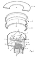
- such a lighting device mainly consists of a plurality of light-emitting means 1 having printed circuit board 2, which is protectively surrounded by a housing.
- the housing essentially consists of a base part 3 made of plastic and one above it arranged, the cover part 4 having intermediate part 5, whereby the housing consists of three parts. Both the cover part 4 and the intermediate part 5 are made of stainless steel, wherein the cover part 4 is connected by welding to the intermediate part 5.
- the cover part 4 forms after installation z.
- the outer visible surface of the housing and has in the present case a circular light exit region 6.
- the housing is provided with a plug connection device 7, the plug contact parts 8 are on the one hand for connecting a plug connection coupling, not shown for simplicity out of the housing to the outside, the plug contact parts 8 on the other hand via a soldering process directly to tracks 9 of the circuit board 2 are connected, in particular out FIG. 2 evident.
- the other hand, projecting into the housing interior end portions of the plug contact parts 8 are each provided with a shoulder 10 on which the circuit board 2 is supported exactly positioned so that a secure and accurate positioning of the circuit board 2 in the interior of the housing is ensured in a simple manner.
- the connector device 7 is provided with a base part 11, which on the one hand has a screw thread for the connection of a connector coupling, not shown, and on the other hand, a piece protrudes into the interior of the housing and is also provided there with a screw thread.
- the circuit board 2 On the circuit board 2, three designed as LED bulbs 1 are arranged, which are connected to the brightness control and / or color control with a control device. Both monochrome and multicolor light sources 1 or LEDs can be used.
- the control device provided for the lamps 1 or LEDs is arranged entirely on the printed circuit board 2.
- the control device can also be completely remote from the place or, on the one hand, it can be remote-controlled and, on the other hand, arranged on the printed circuit board.
- the supply device there is the same possibility, namely to arrange them entirely on the circuit board 2 or completely remote from the place or to a part locally remote and to arrange the other part on the circuit board 2.
- the interior of the housing with three different potting compound V1, V2, V3 is filled.
- the light exit region 6 forming the first potting compound V1 has a comparatively high hardness and has a light-scattering effect.
- the first potting compound V1 is filled into the housing, in which the intermediate part 5 provided with the cover part 4 is placed with its light exit region 6 upside down on a potting substrate.
- the casting underlay contains a structuring, so that the light exit region 6 is provided on its outer surface with a light extraction structure.
- the second potting compound V2 has a comparatively low hardness and is clearly transparent.
- the second potting compound V2 surrounds the printed circuit board 2 with the components arranged thereon, such as lighting means 1, control device, etc., completely, so that decoupling of the printed circuit board 2 from the occurrence of mechanical loads is ensured.
- the third potting compound V3 in turn has a comparatively high hardness and is also clearly transparent.
- the second potting compound V2 is filled into the housing, in which the intermediate part 5 provided with the cover part 4 is placed on the base part 3 and the housing is then placed with its light exit region 6 upside down on a base.
- the second potting compound V2 is filled over the filling opening 12 in the housing until it is ensured that the circuit board 2 is completely surrounded by the second potting compound V2.
- the third potting compound V3 is filled into the interior of the housing until it is completely filled or the third potting compound V3 has penetrated into the filling opening 12 surrounding riser. The displaced during casting with the second potting compound V2 and the third potting compound V3 escapes air through the vent opening 13.
- the vent opening 13 is also surrounded by a riser.
- Both the connector assembly 7 and the filling opening 12 and the vent opening 13 are mounted or arranged on the bottom wall 14 of the housing opposite the light exit region 6.
- a plurality of retaining lugs 15 are formed on the outer wall of the intermediate part 5, which ensure that the lighting device held positionally secure at its installation location, such as floors, walkways, driveways, ceilings, etc. remains.
- the illumination device has a round outer contour.
- the light exit area 6 is designed to be round and there is only a single light exit area 6 available. It also applies to the light exit region 6 that this can be carried out geometrically as desired, as well as a plurality of light exit regions 6, which are also designed in different ways.
- the light exit region 6 is formed on the outside by the first potting compound V1, but it is just as possible to realize the outer region of the light exit region 6 by means of an additional optical disk.
- the housing is not made as stringent in terms of tightness as in the present case, it is also possible to use a lighting device whose interior remains free of any potting compound.
- the base 3 is made entirely of potting compound V1, V2, V3, so that a separate housing for the base 3 can be omitted entirely.
Landscapes
- Engineering & Computer Science (AREA)
- General Engineering & Computer Science (AREA)
- Non-Portable Lighting Devices Or Systems Thereof (AREA)
- Arrangement Of Elements, Cooling, Sealing, Or The Like Of Lighting Devices (AREA)
Applications Claiming Priority (1)
| Application Number | Priority Date | Filing Date | Title |
|---|---|---|---|
| DE102009014514A DE102009014514B4 (de) | 2009-03-23 | 2009-03-23 | Beleuchtungseinrichtung |
Publications (2)
| Publication Number | Publication Date |
|---|---|
| EP2241797A2 true EP2241797A2 (fr) | 2010-10-20 |
| EP2241797A3 EP2241797A3 (fr) | 2013-11-13 |
Family
ID=42244249
Family Applications (1)
| Application Number | Title | Priority Date | Filing Date |
|---|---|---|---|
| EP10150721.8A Withdrawn EP2241797A3 (fr) | 2009-03-23 | 2010-01-14 | Dispositif d'éclairage |
Country Status (2)
| Country | Link |
|---|---|
| EP (1) | EP2241797A3 (fr) |
| DE (1) | DE102009014514B4 (fr) |
Cited By (5)
| Publication number | Priority date | Publication date | Assignee | Title |
|---|---|---|---|---|
| WO2012150124A1 (fr) * | 2011-05-03 | 2012-11-08 | Osram Ag | Dispositif d'éclairage |
| WO2013034381A3 (fr) * | 2011-09-06 | 2013-05-02 | Osram Opto Semiconductors Gmbh | Moyen d'éclairage et utilisation |
| EP2886949A3 (fr) * | 2013-11-15 | 2015-08-05 | Josef Barthelme GmbH & Co. KG | Bandes de diodes luminescentes élastiques horizontales ou verticales équipées d'une sortie de lumière homogène et leur procédé de fabrication |
| WO2020064092A1 (fr) * | 2018-09-25 | 2020-04-02 | Fraba B.V. | Dispositif de détection |
| LU103029B1 (de) * | 2022-10-18 | 2024-04-18 | Thyssenkrupp Ag | Positionsleuchte |
Families Citing this family (11)
| Publication number | Priority date | Publication date | Assignee | Title |
|---|---|---|---|---|
| EP2489932B1 (fr) | 2011-02-17 | 2015-07-29 | Insta Elektro GmbH | Dispositif d'éclairage |
| DE102011001907A1 (de) | 2011-04-08 | 2012-10-11 | Insta Elektro Gmbh | Beleuchtungseinrichtung |
| DE102011106252A1 (de) * | 2011-07-01 | 2013-01-03 | Siteco Beleuchtungstechnik Gmbh | Leuchte mit Vergussmasse |
| DE102011106853A1 (de) | 2011-07-05 | 2013-01-10 | Wago Verwaltungsgesellschaft Mbh | Einbau-Steckverbinder |
| DE102013001649A1 (de) * | 2013-01-31 | 2014-07-31 | Festool Group Gmbh & Co. Kg | Elektrogerät in Gestalt einer Hand-Werkzeugmaschine oder eines Sauggeräts |
| DE202014102935U1 (de) | 2013-11-07 | 2014-07-04 | Insta Elektro Gmbh | Beleuchtungseinrichtung |
| DE202014102936U1 (de) | 2013-11-07 | 2014-07-04 | Insta Elektro Gmbh | Beleuchtungseinrichtung |
| DE202015103540U1 (de) | 2014-09-18 | 2015-08-17 | Insta Elektro Gmbh | Beleuchtungsanlage |
| DE202016101779U1 (de) | 2015-06-09 | 2016-04-27 | Insta Elektro Gmbh | Beleuchtungsanlage |
| DE102019101559A1 (de) | 2019-01-23 | 2020-07-23 | Dr. Schneider Kunststoffwerke Gmbh | Beleuchtungseinheit, beleuchtbares Bauteil und Verfahren zu dessen Herstellung |
| DE102019104999A1 (de) * | 2019-02-27 | 2020-08-27 | Brehmer Gmbh & Co. Kg | Scheinwerfer, insbesondere Kraftfahrzeugscheinwerfer |
Citations (1)
| Publication number | Priority date | Publication date | Assignee | Title |
|---|---|---|---|---|
| DE10026661A1 (de) | 2000-05-29 | 2001-12-06 | Insta Elektro Gmbh & Co Kg | Universelle LED-Lampe für Innen- und Außenleuchten im Netzbetrieb |
Family Cites Families (9)
| Publication number | Priority date | Publication date | Assignee | Title |
|---|---|---|---|---|
| DE3100920A1 (de) * | 1981-01-14 | 1982-08-05 | Heinrich Steinel KG, 4836 Herzebrock | Orientierungsleuchte |
| DE3639485A1 (de) * | 1986-11-18 | 1988-05-26 | Karl Kapfer | Explosionsgeschuetztes elektrisches geraet |
| US6113248A (en) * | 1997-10-20 | 2000-09-05 | The Standard Products Company | Automated system for manufacturing an LED light strip having an integrally formed connector |
| DE10054212A1 (de) * | 2000-11-02 | 2002-05-08 | Hans Dokoupil | Nachtlicht |
| JP4274935B2 (ja) * | 2003-12-26 | 2009-06-10 | トキコーポレーション株式会社 | 発光ユニット用ケースおよび発光ユニット製造方法 |
| DE202006002797U1 (de) * | 2006-02-20 | 2006-05-11 | Kolb, Klaus | Elektrische Leuchteinrichtung mit Leuchtdioden |
| US7527397B2 (en) * | 2006-09-26 | 2009-05-05 | Chia-Mao Li | Solid state lighting package structure |
| DE102007037821A1 (de) * | 2007-08-10 | 2009-02-12 | Osram Gesellschaft mit beschränkter Haftung | Leuchtmodul |
| DE202007012249U1 (de) * | 2007-08-31 | 2007-10-25 | Seliger, Roland | Flexible Quellsteinleuchte |
-
2009
- 2009-03-23 DE DE102009014514A patent/DE102009014514B4/de not_active Expired - Fee Related
-
2010
- 2010-01-14 EP EP10150721.8A patent/EP2241797A3/fr not_active Withdrawn
Patent Citations (1)
| Publication number | Priority date | Publication date | Assignee | Title |
|---|---|---|---|---|
| DE10026661A1 (de) | 2000-05-29 | 2001-12-06 | Insta Elektro Gmbh & Co Kg | Universelle LED-Lampe für Innen- und Außenleuchten im Netzbetrieb |
Cited By (10)
| Publication number | Priority date | Publication date | Assignee | Title |
|---|---|---|---|---|
| WO2012150124A1 (fr) * | 2011-05-03 | 2012-11-08 | Osram Ag | Dispositif d'éclairage |
| WO2013034381A3 (fr) * | 2011-09-06 | 2013-05-02 | Osram Opto Semiconductors Gmbh | Moyen d'éclairage et utilisation |
| CN103782093A (zh) * | 2011-09-06 | 2014-05-07 | 欧司朗光电半导体有限公司 | 发光机构和应用 |
| US9341361B2 (en) | 2011-09-06 | 2016-05-17 | Osram Opto Semiconductors Gmbh | Light-emitting means and use |
| CN103782093B (zh) * | 2011-09-06 | 2016-12-07 | 欧司朗Oled股份有限公司 | 发光机构和应用 |
| EP2886949A3 (fr) * | 2013-11-15 | 2015-08-05 | Josef Barthelme GmbH & Co. KG | Bandes de diodes luminescentes élastiques horizontales ou verticales équipées d'une sortie de lumière homogène et leur procédé de fabrication |
| EP3361150A1 (fr) * | 2013-11-15 | 2018-08-15 | Josef Barthelme GmbH & Co. KG | Bandes de diodes luminescentes élastiques horizontales ou verticales équipées d'une sortie de lumière homogène et leur procédé de fabrication |
| WO2020064092A1 (fr) * | 2018-09-25 | 2020-04-02 | Fraba B.V. | Dispositif de détection |
| US11365990B2 (en) | 2018-09-25 | 2022-06-21 | Fraba B.V. | Sensor device |
| LU103029B1 (de) * | 2022-10-18 | 2024-04-18 | Thyssenkrupp Ag | Positionsleuchte |
Also Published As
| Publication number | Publication date |
|---|---|
| DE102009014514B4 (de) | 2013-11-21 |
| DE102009014514A1 (de) | 2010-10-07 |
| EP2241797A3 (fr) | 2013-11-13 |
Similar Documents
| Publication | Publication Date | Title |
|---|---|---|
| DE102009014514B4 (de) | Beleuchtungseinrichtung | |
| EP1405377B1 (fr) | Module a diodes electroluminescentes pour dispositifs d'eclairage | |
| DE202004021550U1 (de) | Beleuchtungseinrichtung | |
| EP1347233B1 (fr) | Colonne de signalisation | |
| WO2010092106A1 (fr) | Module d'éclairage et procédé de fabrication d'un module d'éclairage | |
| EP2851609B1 (fr) | Dispositif d'éclairage | |
| EP2845233B1 (fr) | Module de del | |
| EP1983620A2 (fr) | Prise électrique dotée d'un éclairage d'orientation | |
| DE102009042615B4 (de) | Anschlusselement zur elektrischen Anbindung einer LED | |
| WO2012150124A1 (fr) | Dispositif d'éclairage | |
| EP2489932B1 (fr) | Dispositif d'éclairage | |
| DE102009031586B3 (de) | Elektrisches Installationsgerät | |
| EP2508796A2 (fr) | Dispositif d'éclairage | |
| EP2834080B1 (fr) | Plaque en verre composite avec un élément fonctionnel | |
| DE102007047271A1 (de) | Leuchte zur Unterwasser-Illumination | |
| AT12157U1 (de) | Led-leuchte sowie leuchtenkörper für diese und led-trägerplatte | |
| DE102016202621A1 (de) | Lampe | |
| EP3853518A1 (fr) | Module d'éclairage, notamment destiné à être utilisé dans un dispositif d'éclairage pour véhicule automobile | |
| DE102008017612A1 (de) | Leuchtbaugruppe | |
| DE202012008617U1 (de) | Leuchte zum Anschluss an Flachkabelleitungen | |
| DE202014102936U1 (de) | Beleuchtungseinrichtung | |
| DE102004044544A1 (de) | Vorrichtung zur Beleuchtung der Bedienungsblende einer Waschmaschine über das Elektronikgehäuse | |
| DE202008013198U1 (de) | Beleuchtungseinrichtung | |
| DE102004020314B4 (de) | Sprech- und/oder Videoeinrichtung | |
| DE202014102935U1 (de) | Beleuchtungseinrichtung |
Legal Events
| Date | Code | Title | Description |
|---|---|---|---|
| PUAI | Public reference made under article 153(3) epc to a published international application that has entered the european phase |
Free format text: ORIGINAL CODE: 0009012 |
|
| AK | Designated contracting states |
Kind code of ref document: A2 Designated state(s): AT BE BG CH CY CZ DE DK EE ES FI FR GB GR HR HU IE IS IT LI LT LU LV MC MK MT NL NO PL PT RO SE SI SK SM TR |
|
| AX | Request for extension of the european patent |
Extension state: AL BA RS |
|
| RAP1 | Party data changed (applicant data changed or rights of an application transferred) |
Owner name: INSTA ELEKTRO GMBH |
|
| RAP1 | Party data changed (applicant data changed or rights of an application transferred) |
Owner name: INSTA ELEKTRO GMBH |
|
| PUAL | Search report despatched |
Free format text: ORIGINAL CODE: 0009013 |
|
| AK | Designated contracting states |
Kind code of ref document: A3 Designated state(s): AT BE BG CH CY CZ DE DK EE ES FI FR GB GR HR HU IE IS IT LI LT LU LV MC MK MT NL NO PL PT RO SE SI SK SM TR |
|
| AX | Request for extension of the european patent |
Extension state: AL BA RS |
|
| RIC1 | Information provided on ipc code assigned before grant |
Ipc: F21V 15/01 20060101ALN20131008BHEP Ipc: F21V 31/04 20060101ALI20131008BHEP Ipc: F21W 111/02 20060101ALN20131008BHEP Ipc: F21S 8/02 20060101ALN20131008BHEP Ipc: F21Y 101/02 20060101ALN20131008BHEP Ipc: F21V 19/00 20060101AFI20131008BHEP Ipc: F21V 23/06 20060101ALI20131008BHEP Ipc: F21V 27/02 20060101ALI20131008BHEP |
|
| STAA | Information on the status of an ep patent application or granted ep patent |
Free format text: STATUS: THE APPLICATION IS DEEMED TO BE WITHDRAWN |
|
| 18D | Application deemed to be withdrawn |
Effective date: 20140514 |