EP2834080B1 - Plaque en verre composite avec un élément fonctionnel - Google Patents
Plaque en verre composite avec un élément fonctionnel Download PDFInfo
- Publication number
- EP2834080B1 EP2834080B1 EP13716165.9A EP13716165A EP2834080B1 EP 2834080 B1 EP2834080 B1 EP 2834080B1 EP 13716165 A EP13716165 A EP 13716165A EP 2834080 B1 EP2834080 B1 EP 2834080B1
- Authority
- EP
- European Patent Office
- Prior art keywords
- main glass
- technical module
- panel
- plate element
- main
- Prior art date
- Legal status (The legal status is an assumption and is not a legal conclusion. Google has not performed a legal analysis and makes no representation as to the accuracy of the status listed.)
- Not-in-force
Links
Images



Classifications
-
- B—PERFORMING OPERATIONS; TRANSPORTING
- B44—DECORATIVE ARTS
- B44C—PRODUCING DECORATIVE EFFECTS; MOSAICS; TARSIA WORK; PAPERHANGING
- B44C5/00—Processes for producing special ornamental bodies
- B44C5/04—Ornamental plaques, e.g. decorative panels, decorative veneers
-
- G—PHYSICS
- G03—PHOTOGRAPHY; CINEMATOGRAPHY; ANALOGOUS TECHNIQUES USING WAVES OTHER THAN OPTICAL WAVES; ELECTROGRAPHY; HOLOGRAPHY
- G03B—APPARATUS OR ARRANGEMENTS FOR TAKING PHOTOGRAPHS OR FOR PROJECTING OR VIEWING THEM; APPARATUS OR ARRANGEMENTS EMPLOYING ANALOGOUS TECHNIQUES USING WAVES OTHER THAN OPTICAL WAVES; ACCESSORIES THEREFOR
- G03B15/00—Special procedures for taking photographs; Apparatus therefor
- G03B15/02—Illuminating scene
- G03B15/03—Combinations of cameras with lighting apparatus; Flash units
-
- B—PERFORMING OPERATIONS; TRANSPORTING
- B32—LAYERED PRODUCTS
- B32B—LAYERED PRODUCTS, i.e. PRODUCTS BUILT-UP OF STRATA OF FLAT OR NON-FLAT, e.g. CELLULAR OR HONEYCOMB, FORM
- B32B3/00—Layered products comprising a layer with external or internal discontinuities or unevennesses, or a layer of non-planar shape; Layered products comprising a layer having particular features of form
- B32B3/10—Layered products comprising a layer with external or internal discontinuities or unevennesses, or a layer of non-planar shape; Layered products comprising a layer having particular features of form characterised by a discontinuous layer, i.e. formed of separate pieces of material
-
- F—MECHANICAL ENGINEERING; LIGHTING; HEATING; WEAPONS; BLASTING
- F21—LIGHTING
- F21V—FUNCTIONAL FEATURES OR DETAILS OF LIGHTING DEVICES OR SYSTEMS THEREOF; STRUCTURAL COMBINATIONS OF LIGHTING DEVICES WITH OTHER ARTICLES, NOT OTHERWISE PROVIDED FOR
- F21V33/00—Structural combinations of lighting devices with other articles, not otherwise provided for
- F21V33/006—General building constructions or finishing work for buildings, e.g. roofs, gutters, stairs or floors; Garden equipment; Sunshades or parasols
-
- B—PERFORMING OPERATIONS; TRANSPORTING
- B32—LAYERED PRODUCTS
- B32B—LAYERED PRODUCTS, i.e. PRODUCTS BUILT-UP OF STRATA OF FLAT OR NON-FLAT, e.g. CELLULAR OR HONEYCOMB, FORM
- B32B17/00—Layered products essentially comprising sheet glass, or glass, slag, or like fibres
- B32B17/06—Layered products essentially comprising sheet glass, or glass, slag, or like fibres comprising glass as the main or only constituent of a layer, next to another layer of a specific material
-
- B—PERFORMING OPERATIONS; TRANSPORTING
- B32—LAYERED PRODUCTS
- B32B—LAYERED PRODUCTS, i.e. PRODUCTS BUILT-UP OF STRATA OF FLAT OR NON-FLAT, e.g. CELLULAR OR HONEYCOMB, FORM
- B32B37/00—Methods or apparatus for laminating, e.g. by curing or by ultrasonic bonding
- B32B37/14—Methods or apparatus for laminating, e.g. by curing or by ultrasonic bonding characterised by the properties of the layers
- B32B37/16—Methods or apparatus for laminating, e.g. by curing or by ultrasonic bonding characterised by the properties of the layers with all layers existing as coherent layers before laminating
- B32B37/18—Methods or apparatus for laminating, e.g. by curing or by ultrasonic bonding characterised by the properties of the layers with all layers existing as coherent layers before laminating involving the assembly of discrete sheets or panels only
-
- F—MECHANICAL ENGINEERING; LIGHTING; HEATING; WEAPONS; BLASTING
- F21—LIGHTING
- F21V—FUNCTIONAL FEATURES OR DETAILS OF LIGHTING DEVICES OR SYSTEMS THEREOF; STRUCTURAL COMBINATIONS OF LIGHTING DEVICES WITH OTHER ARTICLES, NOT OTHERWISE PROVIDED FOR
- F21V29/00—Protecting lighting devices from thermal damage; Cooling or heating arrangements specially adapted for lighting devices or systems
- F21V29/50—Cooling arrangements
-
- G—PHYSICS
- G02—OPTICS
- G02B—OPTICAL ELEMENTS, SYSTEMS OR APPARATUS
- G02B6/00—Light guides; Structural details of arrangements comprising light guides and other optical elements, e.g. couplings
- G02B6/0001—Light guides; Structural details of arrangements comprising light guides and other optical elements, e.g. couplings specially adapted for lighting devices or systems
- G02B6/0011—Light guides; Structural details of arrangements comprising light guides and other optical elements, e.g. couplings specially adapted for lighting devices or systems the light guides being planar or of plate-like form
- G02B6/0075—Arrangements of multiple light guides
- G02B6/0076—Stacked arrangements of multiple light guides of the same or different cross-sectional area
-
- G—PHYSICS
- G03—PHOTOGRAPHY; CINEMATOGRAPHY; ANALOGOUS TECHNIQUES USING WAVES OTHER THAN OPTICAL WAVES; ELECTROGRAPHY; HOLOGRAPHY
- G03B—APPARATUS OR ARRANGEMENTS FOR TAKING PHOTOGRAPHS OR FOR PROJECTING OR VIEWING THEM; APPARATUS OR ARRANGEMENTS EMPLOYING ANALOGOUS TECHNIQUES USING WAVES OTHER THAN OPTICAL WAVES; ACCESSORIES THEREFOR
- G03B17/00—Details of cameras or camera bodies; Accessories therefor
- G03B17/02—Bodies
-
- G—PHYSICS
- G03—PHOTOGRAPHY; CINEMATOGRAPHY; ANALOGOUS TECHNIQUES USING WAVES OTHER THAN OPTICAL WAVES; ELECTROGRAPHY; HOLOGRAPHY
- G03B—APPARATUS OR ARRANGEMENTS FOR TAKING PHOTOGRAPHS OR FOR PROJECTING OR VIEWING THEM; APPARATUS OR ARRANGEMENTS EMPLOYING ANALOGOUS TECHNIQUES USING WAVES OTHER THAN OPTICAL WAVES; ACCESSORIES THEREFOR
- G03B17/00—Details of cameras or camera bodies; Accessories therefor
- G03B17/55—Details of cameras or camera bodies; Accessories therefor with provision for heating or cooling, e.g. in aircraft
-
- H—ELECTRICITY
- H05—ELECTRIC TECHNIQUES NOT OTHERWISE PROVIDED FOR
- H05K—PRINTED CIRCUITS; CASINGS OR CONSTRUCTIONAL DETAILS OF ELECTRIC APPARATUS; MANUFACTURE OF ASSEMBLAGES OF ELECTRICAL COMPONENTS
- H05K1/00—Printed circuits
- H05K1/02—Details
- H05K1/0274—Optical details, e.g. printed circuits comprising integral optical means
-
- H—ELECTRICITY
- H05—ELECTRIC TECHNIQUES NOT OTHERWISE PROVIDED FOR
- H05K—PRINTED CIRCUITS; CASINGS OR CONSTRUCTIONAL DETAILS OF ELECTRIC APPARATUS; MANUFACTURE OF ASSEMBLAGES OF ELECTRICAL COMPONENTS
- H05K1/00—Printed circuits
- H05K1/02—Details
- H05K1/03—Use of materials for the substrate
- H05K1/0306—Inorganic insulating substrates, e.g. ceramic, glass
-
- B—PERFORMING OPERATIONS; TRANSPORTING
- B32—LAYERED PRODUCTS
- B32B—LAYERED PRODUCTS, i.e. PRODUCTS BUILT-UP OF STRATA OF FLAT OR NON-FLAT, e.g. CELLULAR OR HONEYCOMB, FORM
- B32B2457/00—Electrical equipment
-
- B—PERFORMING OPERATIONS; TRANSPORTING
- B32—LAYERED PRODUCTS
- B32B—LAYERED PRODUCTS, i.e. PRODUCTS BUILT-UP OF STRATA OF FLAT OR NON-FLAT, e.g. CELLULAR OR HONEYCOMB, FORM
- B32B2457/00—Electrical equipment
- B32B2457/12—Photovoltaic modules
-
- C—CHEMISTRY; METALLURGY
- C03—GLASS; MINERAL OR SLAG WOOL
- C03C—CHEMICAL COMPOSITION OF GLASSES, GLAZES OR VITREOUS ENAMELS; SURFACE TREATMENT OF GLASS; SURFACE TREATMENT OF FIBRES OR FILAMENTS MADE FROM GLASS, MINERALS OR SLAGS; JOINING GLASS TO GLASS OR OTHER MATERIALS
- C03C27/00—Joining pieces of glass to pieces of other inorganic material; Joining glass to glass other than by fusing
- C03C27/06—Joining glass to glass by processes other than fusing
-
- F—MECHANICAL ENGINEERING; LIGHTING; HEATING; WEAPONS; BLASTING
- F21—LIGHTING
- F21V—FUNCTIONAL FEATURES OR DETAILS OF LIGHTING DEVICES OR SYSTEMS THEREOF; STRUCTURAL COMBINATIONS OF LIGHTING DEVICES WITH OTHER ARTICLES, NOT OTHERWISE PROVIDED FOR
- F21V29/00—Protecting lighting devices from thermal damage; Cooling or heating arrangements specially adapted for lighting devices or systems
- F21V29/50—Cooling arrangements
- F21V29/502—Cooling arrangements characterised by the adaptation for cooling of specific components
- F21V29/508—Cooling arrangements characterised by the adaptation for cooling of specific components of electrical circuits
-
- F—MECHANICAL ENGINEERING; LIGHTING; HEATING; WEAPONS; BLASTING
- F21—LIGHTING
- F21Y—INDEXING SCHEME ASSOCIATED WITH SUBCLASSES F21K, F21L, F21S and F21V, RELATING TO THE FORM OR THE KIND OF THE LIGHT SOURCES OR OF THE COLOUR OF THE LIGHT EMITTED
- F21Y2105/00—Planar light sources
- F21Y2105/10—Planar light sources comprising a two-dimensional [2D] array of point-like light-generating elements
-
- F—MECHANICAL ENGINEERING; LIGHTING; HEATING; WEAPONS; BLASTING
- F21—LIGHTING
- F21Y—INDEXING SCHEME ASSOCIATED WITH SUBCLASSES F21K, F21L, F21S and F21V, RELATING TO THE FORM OR THE KIND OF THE LIGHT SOURCES OR OF THE COLOUR OF THE LIGHT EMITTED
- F21Y2115/00—Light-generating elements of semiconductor light sources
- F21Y2115/10—Light-emitting diodes [LED]
-
- G—PHYSICS
- G01—MEASURING; TESTING
- G01D—MEASURING NOT SPECIALLY ADAPTED FOR A SPECIFIC VARIABLE; ARRANGEMENTS FOR MEASURING TWO OR MORE VARIABLES NOT COVERED IN A SINGLE OTHER SUBCLASS; TARIFF METERING APPARATUS; MEASURING OR TESTING NOT OTHERWISE PROVIDED FOR
- G01D11/00—Component parts of measuring arrangements not specially adapted for a specific variable
- G01D11/24—Housings ; Casings for instruments
-
- G—PHYSICS
- G01—MEASURING; TESTING
- G01D—MEASURING NOT SPECIALLY ADAPTED FOR A SPECIFIC VARIABLE; ARRANGEMENTS FOR MEASURING TWO OR MORE VARIABLES NOT COVERED IN A SINGLE OTHER SUBCLASS; TARIFF METERING APPARATUS; MEASURING OR TESTING NOT OTHERWISE PROVIDED FOR
- G01D11/00—Component parts of measuring arrangements not specially adapted for a specific variable
- G01D11/28—Structurally-combined illuminating devices
-
- G—PHYSICS
- G01—MEASURING; TESTING
- G01D—MEASURING NOT SPECIALLY ADAPTED FOR A SPECIFIC VARIABLE; ARRANGEMENTS FOR MEASURING TWO OR MORE VARIABLES NOT COVERED IN A SINGLE OTHER SUBCLASS; TARIFF METERING APPARATUS; MEASURING OR TESTING NOT OTHERWISE PROVIDED FOR
- G01D7/00—Indicating measured values
-
- G—PHYSICS
- G02—OPTICS
- G02B—OPTICAL ELEMENTS, SYSTEMS OR APPARATUS
- G02B7/00—Mountings, adjusting means, or light-tight connections, for optical elements
-
- G—PHYSICS
- G06—COMPUTING OR CALCULATING; COUNTING
- G06F—ELECTRIC DIGITAL DATA PROCESSING
- G06F3/00—Input arrangements for transferring data to be processed into a form capable of being handled by the computer; Output arrangements for transferring data from processing unit to output unit, e.g. interface arrangements
- G06F3/01—Input arrangements or combined input and output arrangements for interaction between user and computer
-
- G—PHYSICS
- G09—EDUCATION; CRYPTOGRAPHY; DISPLAY; ADVERTISING; SEALS
- G09F—DISPLAYING; ADVERTISING; SIGNS; LABELS OR NAME-PLATES; SEALS
- G09F13/00—Illuminated signs; Luminous advertising
- G09F13/04—Signs, boards or panels, illuminated from behind the insignia
Definitions
- the invention relates to a glass composite with at least one first main glass sheet, at least one second main glass sheet arranged at a distance therefrom, and at least one plate element arranged between the main glass sheets.
- the invention also relates to a method for producing such a glass composite.
- a generic glass composite is from WO 2003/048494 known.
- the glass composite disclosed there can be used architecturally in an advantageous manner.
- the invention is based on the object of expanding the area of application of the known glass composite beyond purely architectural use.
- At least one technical module is arranged between the two main glass panels and that the plate element at least partially delimits or defines a recess adapted to the shape of the technical module in which the technical module is accommodated, and that lighting is integrated between two main glass panels and are designed for the lateral feed of light between the main glass panels and that the Lighting means are thermally coupled to a spacer.
- At least one technical module is arranged in a recess of the at least one plate element adapted to the shape of the technical module and that the at least one plate element and the at least one technical module are arranged between the two main glass panels and that lighting means between the main glass panels are integrated, which are designed for the lateral feed of light between the main glass panels, and that the lighting means are thermally coupled with a spacer.
- a technical module is not to be understood as a plate element in the sense of this patent application. This module is therefore a different element from the plate element.
- the measures according to the invention advantageously mean that the technical module or the technical modules are now integrated or received in the glass composite in a dust-proof and scratch-proof manner.
- a glass composite designed in this way not only aesthetically pleasing but also functional elements can be integrated into the architecture.
- the two main glass panels can realize a front and a rear wall of the glass composite.
- the main glass panels can be made from all types of glass in technical structures and thicknesses, from transparent and translucent plastics, etc.
- the plate element is preferably transparent, in particular colorless or colored, with the plate element advantageously being made, for example, of transparent or translucent plastic, in particular of acrylic glass (e.g. PMMA polymethyl methacrylate). However, metals, minerals, wood, etc. can also be used as materials for the panel element.
- the plate element is usually aligned parallel to the main glass panels and is approximately the same size as the main glass panels, but in particular is made smaller than the main glass panels by elements in the edge area.
- the plate element or the plate elements act (s) as retaining disk (s) or frame for the module.
- the only plate element is or the plate elements are arranged in a plane between the main glass panels. This level can be understood as a functional level because the module brings a technical function into the glass composite.
- the at least one plate element is arranged between the two main glass panels in a functional level and acts as a frame within this functional level for at least one technical module by delimiting a recess adapted to the shape of the technical module, in which the technical module is included.
- At least one technical module is thus at least one in a recess adapted to the shape of the technical module
- a functional level arranged plate element arranged such that the at least one plate element acts as a frame for the technical module within this functional level, and that the at least one plate element and the at least one technical module are arranged between the two main glass panels.
- Such a plate element can, for example, be constructed in one or more parts.
- the total area occupied by the one or multi-part plate element and the module, which are both arranged in a plane (functional plane) parallel to the main glass panels, corresponds approximately to the total area of the glass composite.
- the recess can be completely defined by a hole in the plate element.
- the recess can, however, also be located at the edge of the plate element and limit, for example, two or three sides of the recess. The remaining sides of the recess can be realized by the edge of the glass composite.
- individual plate elements can be arranged next to one another in the plane between the main glass plates, at least in some areas, flush with one another.
- the recess can be contained in one of the plate elements and the other plate element or elements can be free of recesses.
- adjacent plate elements can also have cutouts on their edges pointing towards one another, which in total realize the shape of the cutout to be defined for the module. This is exactly in this cutout or this recess in the transition area between the plate elements Module inserted. Even with a multi-part design, both the plate element (s) and the module are located in the plane between the main glass panels (functional plane).
- the plate element and the technical module can extend from the first main glass panel to the second main glass panel. It is also possible that the plate element not only forms a lateral frame for the technical module but, if the depth of the technical module is less than the distance between the two main glass panels, also extends over the front and / or back of the technical module .
- the plate element is designed in several parts, that is to say at least in two parts.
- the recess in which the module is received is formed along one of the two plate elements or both plate elements.
- the module is thus arranged in a border area between the at least two plate elements. It is therefore also possible for plate elements arranged adjacently to have recesses on their edges which are adjacent to one another or which point towards one another, which in total realize the shape of the recess to be defined for the module.
- the number of plate elements can be selected according to the optical effects to be achieved in each case.
- the plate elements are made from glass-like panels, hereinafter referred to as frame glass panels, with the frame glass panels having different transparency or different colors for aesthetic reasons, but also for privacy reasons.
- sensory Functions of the module or modules can be assigned to a less transparent area, whereas modules used for visualization or areas of such modules are assigned to a more transparent area.
- the module is preferably selected from a group of the following elements: display unit (e.g. monitor); Input unit such as buttons or keyboard or the like; Sensor unit; Photovoltaic panel; Device that carries current and / or data and / or records data, in particular a camera.
- display unit e.g. monitor
- Input unit such as buttons or keyboard or the like
- Sensor unit Photovoltaic panel
- Device that carries current and / or data and / or records data, in particular a camera.
- a sensor unit can, for example, detect air pressure or temperature if it is connected to the surroundings of the glass composite via sensor elements.
- the power supply of the individual elements can be ensured e.g. with the help of an integrated photovoltaic panel, so that an autonomous operation is possible.
- the glass composite does not have to function autonomously, in which case the individual elements are connected to the surroundings of the glass composite in the form of wireless or wire-based information or energy or power transmission.
- the technical module can be an electronic or mechanical or e.g. module based on physical principles, such as a mercury thermometer or a barometer or an optical lens.
- At least one of the main glass panels and the module are in the glass composite with the aid of a Spacers are arranged at a distance from one another in such a way that cooling of the module is ensured.
- the spacer ensures that an air space provided for cooling is maintained between at least one of the main glass panels and the module and / or the plate element. This distance is dimensioned in such a way that it allows air convection in accordance with the cooling when the module is in operation. If the air space is only formed on one side, ie provided in front of or behind the module, it can have a depth of 5% to 90% of the depth of the module.
- the advantage is obtained that reliable cooling or heat dissipation from the module into the vicinity of the gas network is ensured.
- the glass composite has line means which are provided for the electrically conductive connection of the electrical connections of the module to the surroundings of the glass composite.
- Such conduction means can have a bore or notch or groove and an electrical line received there in the plate element and / or have line or surface-like first conduction paths running on the edges of the plate element and / or have spacers inserted between the main glass panels on the edge side, which the spacing of the main glass panels to each other, wherein the spacer is part of the conduction means and has electrically conductive structures in some areas, in particular in the form of cable, line or area-like second conduction paths, and / or with corner elements between the Spacers form part of the line means and have an electrically conductive leadthrough in order to electrically connect the module to the surroundings of the glass composite.
- the hole, notch, groove or lines incorporated therein can be used deliberately for design purposes.
- shapes that are as inconspicuous as possible such as said line-like or area-like, first conductive paths, can be used, or the material of the plate elements can be opaque (opaque).
- These conductor tracks can also be covered with insulating layers and layered next to one another or on top of one another along the edges of the plate element. In the area of the accommodated module, they end where they are in contact with electrical contacts or electrical lines of the module.
- light guides can also be provided which, depending on the application, are either integrated into the respective plate element in an optically inconspicuous manner or give an optical accent or run on its surface.
- the spacer is also a component of the conduction means and has an electrically conductive structure in certain areas, in particular in the form of cable-like, line-like or area-like, second conductive paths. These second conductor tracks end at those areas in which the first conductor tracks of the respective plate element end. There are the second conductor tracks with the aforementioned electrical Ladders connected.
- the spacer can for example be a hollow body - for example a hollow profile rod - and lines can be received in it.
- the spacer can, however, also be formed by a structure made of electrically conductive material, such as two or more metallically conductive parts separated along its longitudinal extension, which are connected to one another by an insulating part, so that the spacer itself realizes a two-wire or multi-wire line .
- Light guides which are coupled with light guides in the respective plate element, can also be integrated in the spacer for signal transmission.
- the spacers running along the edges of the glass composite are connected to one another at the corners of the glass composite by corner elements.
- the tightness of the glass composite is also ensured by the corner element because the sealing material and other materials of the glass composite do not have to be broken through. Accordingly, these corner elements between the spacers are also part of the line means and have an electrically conductive leadthrough in order to electrically connect the module to the surroundings of the glass composite without endangering the tightness of the glass composite.
- the electrically conductive bushing can be implemented with the aid of a cable.
- the cable can end in any connector outside of the glass composite.
- the electrically conductive leadthrough is preferably implemented by a plug integrated in the corner element, which allows power to be introduced from the outside by means of a cable and thus connects the power-consuming elements located within the spacer and implements their power connection.
- the glass composite consists of only two main glass panels and a single functional level extends between these main glass panels.
- lighting means can be integrated between the two main glass panels and provided for the lateral feeding of light between the main glass panels in a plate edge of the plate element.
- Said lighting means can have so-called fluorescent lamps or energy-saving lamps.
- the lighting means have one or more light-emitting diodes, in particular in the form of a light-emitting diode strip. Said illuminants are arranged on the edge of the glass composite between the main glass panels and radiate light into the areas between the main glass panels.
- the light is thus radiated from the side (edge side) and exits over the surface (front and / or rear surface) of the plate elements.
- the module or modules is illuminated with this light.
- this light can be used to illuminate the area around the glass composite.
- the glass composite adjacent to one of the main glass panels in particular that main glass panel facing a rear side of the module, can have a lighting layer that runs in a plane parallel to said main glass panel and an embedded light-guiding lighting panel between said main glass panel and a third main glass panel having.
- the lighting glass panels are arranged in front of the module in the viewing direction, the entire module appears in the chosen color of the light.
- the color can also be selected by the color of the lighting glass panel.
- the lighting glass panel is arranged behind the module, that is to say the module is mounted in the viewing direction in front of the lighting glass panel, the module appears illuminated from the background.
- the lighting glass panel can illuminate both the area in front of the glass composite and the area behind the glass composite with a light of the same color.
- the glass composite has a color layer adjacent to one of the main glass panels, in particular that main glass panel facing a rear side of the module, which runs in a plane parallel to said main glass panel and is embedded between said main glass panel and a further main glass panel Has color plate.
- the additional color panel allows the provision of additional optical functions, such as privacy protection from, for example, the rear, in order to optically hide the module or other elements of the glass composite; Sunscreen; if the color plane is illuminated from within the glass composite, color effects can also be achieved with it, such as a different light color behind the glass composite than in front of the glass composite.
- the glass composite consequently has a light panel (lighting panel) arranged in relation to the mounting panel (main glass panel), the light panel being formed from light-conducting material.
- the mounting disc can be illuminated over its entire surface by light feeds on at least one side edge of the luminous disc and light exit via its surface facing the mounting disc, with a spacer material being provided flat between the mounting disc and the luminous disc, which has one of the refractive index of the Color disc (color table) has a different refractive index.
- the light panel also forms a lighting fixture that produces ambient light that shines beyond the glass composite, illuminating the area around the glass composite, so to speak.
- the light-emitting diodes preferably the light-emitting diode strip
- the light-emitting diodes are arranged on the right and / or left and / or upper edge of the glass composite.
- Direction-dependent light impressions or homogeneous illumination that is, direction-independent illumination, can thus be achieved.
- the individual light-emitting diode strips can also be supplied with power at different times and can thus achieve light-dynamic effects.
- the lighting means are thermally coupled to the spacer.
- the lighting means are arranged within the spacer with respect to the outer edge of the glass composite and produce heat there.
- the thermal coupling is particularly advantageous when the spacers are made of a material with good thermal conductivity, in particular a metal (for example aluminum) or an alloy.
- the thermal coupling of the lighting means and spacer creates a heat sink, with the help of which the heat generated by the lighting means can be efficiently transported out of the glass composite.
- the thermal coupling can take place through close contact of the parts with one another, such as gluing them to one another or with the aid of a thermal paste, etc.
- said heat sink can also be used to dissipate heat that is generated by the operation of the module in the glass composite.
- the spacer is implemented in the form of a hollow profile, so that the largest possible surface is available for cooling.
- the lighting means have a light-emitting diode strip having a circuit board with light-emitting diodes attached to it.
- the board serves as a heat sink for heat dissipation.
- Such a glass composite can be produced as follows. First, the main glass panels are manufactured and provided and framed with appropriate positioning and delimiting parts (spacers, corner elements, elastic edge elements). The rear main glass panel is laid flat. The respective plate element and the module inserted into the recess are placed on this main glass panel and the module is connected to the electrical lines (eg power supply lines). Then the front main glass panel is placed on the primary seal. Accordingly, at least one glass-like plate element is arranged between two main glass panels, the at least one plate element defining a recess adapted to the size of the module, and said module being arranged in said recess. As already mentioned at the beginning, the plate element can also be designed in several parts. In this case the module can be divided into two or several plate elements limited recess can be used.
- lighting means can also be included in the glass composite, which are integrated between the main glass panels and which are designed to feed in light from the side between the main glass panels.
- the lighting means can be integrated in the plane of the module or in a plane adjacent to it.
- the lighting means are, as mentioned, thermally coupled to the spacer located further outward in relation to the center of the glass composite in order to achieve the aforementioned effects.
- the assembled glass composite can now be set up and the electrical module can be put into operation.
- Those elements which comprise the plate element or elements together with the module in a frame-like manner essentially serve three functions, namely spacing and elastic support, defining a distance between the plate element and the edges of the glass composite, and tightness of the glass composite. This protects the electrical module from moisture and other environmental influences.
- the invention discloses a technical method by which technical modules such as monitors, displays, sensors can be inserted into the glass and at the same time their lighting and that of the glass surface are guaranteed.
- technical modules such as monitors, displays, sensors can be inserted into the glass and at the same time their lighting and that of the glass surface are guaranteed.
- plate-shaped, for example acrylic glass elements are placed in a glass composite, the openings of which can accommodate the various technical parts (modules) and their cabling according to the needs and at the same time form a holder for these technical parts.
- modules By integrating light sources, these can be used in the glass composite recorded plate elements and their integrated modules are illuminated.
- the technical modules integrated into the glass composite give the impression that they are simply floating in the glass without any mounting brackets.
- the position, location and orientation of the modules can be defined very precisely thanks to the precise machinability of the plate elements or the plate element.
- the expected heat development during operation is taken into account by a corresponding distance to the glass plates.
- the heat dissipation from the light sources, such as the light-emitting diodes is conducted to the outside through a specially designed circuit board (printed circuit board) via the spacer, which is thermally coupled to the circuit board.
- the special arrangement of the modules in the recess of the plate element enables the technical modules to be precisely fitted and secures them in a reliable manner.
- the power and data transmission cables it should be mentioned that these can be integrated into the glass composite in a way that is barely noticeable, not just using conventional cables, but also using specially designed, almost invisible lines or materials.
- a glass composite 1 which has a first main glass panel 2 as a front pane and a second main glass panel 3 as a central pane.
- a functional level or module layer 26 is arranged between the first and the second main glass sheet 2, 3.
- modules 4 are integrated in this module layer 26, for example the top one as a display unit, the two middle ones as an input unit and the one located at the bottom right as a sensor unit.
- Behind the second main glass panel 3, a lighting layer 27 and a third main glass panel 22 adjoining it parallel to it are provided as a rear wall.
- the lighting layer 27 serves to illuminate the rear of the module layer 26 or the modules 4 accommodated therein.
- the module layer 26 and the lighting layer 27 are provided with electrical connections 12 in the area of their corners, which in the present case are designed as cables.
- FIG. 13 is a sectional view taken along the line in FIG Figure 1 To see section plane AA shown, in which further details of the glass composite 1 are visible.
- An arrow 31 indicates a viewing direction onto the glass composite 1.
- the plate element 5 has a recess 6 which is adapted to the shape of the respective module 4 and in which the module 4 is received.
- the plate element 5 is formed by a single frame glass panel 7, which has recesses 6 adapted to the number of modules 4.
- Spacers 9 are inserted between the main glass panels 2, 3, 22 at the edge, which define the distance between the main glass panels 2, 3, 22 in such a way that a gap 10 is formed between the main glass panels 2, 3, 22 and the module 4 and the plate element 5 so that the heat development to be expected in module 4 can be dissipated via the air between module 4 and plate element 5 on the one hand and the respective main glass panel 2, 3, 22 on the other hand.
- the spacer 9 is in turn embedded in a primary seal 28 in the direction of the main glass panels 2, 3, 22.
- Said spacer 9 is also present in the illumination layer 27, embedded in said primary seal 28.
- Said secondary seal 29 is also located outside the spacer 9.
- the elastic edge element 30 in the lighting layer 27 is only formed on the left, right and lower edge.
- a light-emitting diode strip 24 having a number of light-emitting diodes 23 is arranged on the upper edge between a lighting panel or lighting glass panel 21 and the upper spacer 9. The lighting panel 21, together with the light-emitting diode strip 24, forms components of lighting means 19 which are used to illuminate the module layer 26 or the modules 4 accommodated in the module layer 26.
- the lighting means 19 are embedded between the second main glass panel 3 and the third main glass panel 22.
- the light-emitting diodes 23 of the light-emitting diode strip 24 are arranged on the edge of the glass composite 1 between the second main glass panel 3 and the third main glass panel 22 and emit light into the areas between the main glass panels 3 and 22, which light spreads along the lighting panel 21.
- the light emerges from the lighting panel 21 via its front side facing the modules 4 and thus illuminates the modules 4 from behind and shimmers through between them.
- the light emerges from the lighting panel 21 via its rear side, which is oriented parallel to the said front side, and there illuminates the space located behind the glass composite 1.
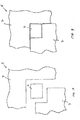
- a plate element 5 is shown according to a further embodiment of the invention.
- This plate element 5 has two frame glass panels 7.
- the left lower frame glass panel 7 has a recess in a shape that allows the module 4 completely to be included or to enclose at its left and lower edge.
- the three elements, namely the two frame glass panels 7 and the module 4 are as in FIG Figure 4 shown arranged. Because of
- Clarity are in the Figure 4 Gaps between the elements 5 and 7 shown, which in reality do not occur to this extent or not at all because of the precisely fitting adaptation of the recesses of the individual frame glass panels 7 to the contour of the module 4. To a viewer of a real training it appears as if the elements merge seamlessly into one another.
- FIG 5 is one to the Figure 3 similar configuration shown in an oblique view.
- the focus is on line means 11, which are formed in the lower left-hand frame glass panel 7 in the form of a bore 13 with an electrical line 14 received therein, the line 14 being electrically conductively connected to the module 4.
- the electrical line 14 is connected to the module 4 in a fixed manner or in a separable manner with the aid of plug connections (not shown).
- a further exemplary embodiment of the conduction means 11 is disclosed, which in the present case are formed on the edges of the frame glass panel 7 arranged at the bottom left in the form of line-like or area-like first conductor tracks 15.
- the line means 11 are contacted by placing the module 4 on.
- the fact that the spacer is part of the line means 11 is not shown in detail has electrically conductive structures in some areas, in particular in the form of cable-like, line-like or area-like second conductor tracks 16, which are connected to the first conductor tracks 15 in an electrically conductive manner.
- the Figure 7 shows a detail of the area of the lighting position 27 located at the top right.
- lighting means 19 are visualized, which are implemented by a light-emitting diode strip 24 having a number of light-emitting diodes 23 attached to a circuit board 32.
- the circuit board 32 is thermally coupled to the spacer element 9.
- a corner element 17 connecting them is shown between adjacent spacers 9.
- the corner element 17 has a bushing 18 into which a cable is inserted as an electrical connection 12, with which the light-emitting diode strip 24 is connected to the surroundings of the glass composite 1.
- a glass composite 1 is shown with a single level between the main glass panels 2 and 3, the lighting function being integrated in the upper part.
- a fourth main glass panel 33 is in the direction of the rear of the module 4 and a color panel 34 is integrated between the main glass panels 3 and 33. With their help, the back of the glass composite 1 appears in a different light color than the front.
Landscapes
- Engineering & Computer Science (AREA)
- Physics & Mathematics (AREA)
- General Physics & Mathematics (AREA)
- General Engineering & Computer Science (AREA)
- Microelectronics & Electronic Packaging (AREA)
- Architecture (AREA)
- Civil Engineering (AREA)
- Structural Engineering (AREA)
- Optics & Photonics (AREA)
- Chemical & Material Sciences (AREA)
- Ceramic Engineering (AREA)
- Inorganic Chemistry (AREA)
- Aviation & Aerospace Engineering (AREA)
- Joining Of Glass To Other Materials (AREA)
- Securing Of Glass Panes Or The Like (AREA)
- Laminated Bodies (AREA)
- Arrangement Of Elements, Cooling, Sealing, Or The Like Of Lighting Devices (AREA)
Claims (14)
- Vitrage composite comprenant au moins une première plaque de verre principale (2), au moins une deuxième plaque de verre principale (3) espacée de la première, et au moins un panneau (5) disposé entre les plaques de verre principales (2, 3), dans lequel au moins un module technique (4) est disposé entre les deux plaques de verre principales (2, 3) et dans lequel le panneau (5) délimite un évidement (6) adapté à la forme du module technique (4) dans lequel le module technique (4) est logé, caractérisé en ce que des moyens d'éclairage (19) sont intégrés entre deux plaques de verre principales (2, 3, 22, 33) et sont conçus pour alimenter la lumière latéralement entre les plaques de verre principales (2, 3, 22, 33), et en ce que les moyens d'éclairage (19) sont couplés thermiquement à une cale d'espacement (9).
- Vitrage composite selon la revendication 1, caractérisé en ce que le panneau (5) est formé en au moins deux parties et en ce que les au moins deux parties touchent aux bords du module technique (4) dans le plan entre les plaques de verre principales (2, 3).
- Vitrage composite selon la revendication 1 ou 2, caractérisé en ce que le module technique (4) est une unité d'affichage, une unité d'entrée, une unité de capteur, un panneau photovoltaïque ou un dispositif de transport de courant et/ou de données et/ou d'enregistrement de données, en particulier une caméra.
- Vitrage composite selon l'une des revendications 1 à 3, caractérisé en ce qu'au moins une des plaques de verre principales (2, 3) et le module technique (4) sont disposés à distance l'un de l'autre à l'aide d'une cale d'espacement (9) de telle façon qu'un refroidissement du module technique (4) est assuré.
- Vitrage composite selon l'une des revendications 1 à 4, caractérisé en ce qu'il est prévu, adjacent à l'une des plaques de verre principales (2, 3), en particulier la plaque de verre principale (3) qui fait face à l'arrière du module technique (4), un système d'éclairage, qui s'étend dans un plan parallèle à ce plaque de verre principale (2, 3) et qui comprend une plaque d'éclairage intégré guidant la lumière (21) entre ce plaque de verre principale (2, 3) et un troisième plaque de verre principale (22).
- Vitrage composite selon l'une des revendications 1 à 5, caractérisé en ce qu'il est prévu, adjacent à l'une des plaques de verre principales (2, 3, 22), en particulier la plaque de verre principale (3, 22) qui fait face à l'arrière du module technique (4), une couche de couleur, qui s'étend dans un plan parallèle à ce plaque de verre principale (2, 3, 22) et qui comprend une plaque de couleur (34) intégrée entre ce plaque de verre principale (2, 3, 22) et une autre plaque de verre principale (33).
- Vitrage composite selon l'une des revendications 1 à 6, caractérisé en ce que des moyens conducteurs (11) sont prévus, qui sont agencés pour la connexion électriquement conductrice des connexions électriques (12) du module technique (4) à l'environnement du vitrage composite (1),- dans lequel les moyens conducteurs (11) dans le panneau (5) sont pourvus d'un trou ou d'une encoche ou d'une rainure (13) et d'une ligne électrique (14) reçue dans celle-ci, et/ou- dans lequel les moyens conducteurs (11) comportent de premiers chemins conducteurs (15) qui s'étendent aux bords du panneau (5) en forme de ligne ou de plan, et/ou- dans lequel des cales d'espacement (9), qui définissent la distance des plaques de verre principales (2, 3) les uns aux autres, sont insérées par leurs bords entre les plaques de verre principales (2, 3), dans lequel la cale d'espacement (9) fait partie des moyens conducteurs (11) et comprend des structures électriquement conductrices dans certaines zones, en particulier sous forme de deuxièmes chemins conductrices (16) sous forme de câbles, de lignes ou de zones, et/ou dans lequel des éléments de coin (17) entre les cales d'espacement (9) font partie des moyens conducteurs (11) et comportent une traversée électriquement conductrice (18), pour la connexion électrique du module technique (4) à l'environnement du vitrage composite (1).
- Vitrage composite selon l'une des revendications 1 à 7, caractérisé en ce que les moyens d'éclairage (19) comportent une bande de diodes électroluminescentes (24) comprenant une carte de circuit imprimé (32) avec des diodes électroluminescentes (23) attachées à celle-ci, et en ce que la carte de circuit imprimé (32) sert de dissipateur de chaleur.
- Vitrage composite selon l'une des revendications 1 à 8, caractérisé en ce que l'au moins un panneau (5) entre les deux plaques de verre principales (2, 3) est agencé dans un plan fonctionnel et, dans ce plan fonctionnel, sert de cadre pour au moins un module technique (4), en délimitant un évidement (6) adapté à la forme du module technique (4) dans lequel le module technique (4) est logé.
- Procédé de fabrication d'un vitrage composite (1) comprenant au moins une première plaque de verre principale (2), au moins une deuxième plaque de verre principale (3) espacée de la première, et au moins un panneau (5) disposé entre les plaques de verre principales (2, 3), dans lequel au moins un module technique (4) est agencé dans un évidement (6) adapté à la forme du module technique (4) de l'au moins un panneau (5), et en ce que l'au moins un panneau (5) et l'au moins un module technique (4) sont agencés entre les deux plaques de verre principales, caractérisé en ce que des moyens d'éclairage (19) sont intégrés entre les plaques de verre principales (2, 3, 22, 33), qui sont conçus pour alimenter la lumière latéralement entre les plaques de verre principales (2, 3, 22, 33), et en ce que les moyens d'éclairage (19) sont couplés thermiquement à une cale d'espacement (9).
- Procédé selon la revendication 10, caractérisé en ce que le panneau (5) est formé en au moins deux parties, dans lequel les parties du panneau (5) sont alignées lors de l'installation de telle manière que des bords du module technique (4) touchent aux bords de panneau des parties du panneau (5) dans le plan entre les plaques de verre principales (2, 3).
- Procédé selon la revendication 10 ou 11, caractérisé en ce que des cales d'espacement (9) sont insérées par leurs bords entre des plaques de verre principales (2, 3), de telle manière qu'au moins une des plaques de verre principales (2, 3) et le module technique (4) sont disposés à distance l'un de l'autre à l'aide des cales d'espacement (9) de telle façon qu'un refroidissement du module technique (4) est assuré.
- Procédé selon l'une des revendications 10 à 12, caractérisé en ce qu'un système d'éclairage, qui s'étend dans un plan parallèle à ce plaque de verre principale (2, 3) et qui comprend une plaque d'éclairage intégré guidant la lumière (21) entre ce plaque de verre principale (2, 3) et un troisième plaque de verre principale (22), est agencé adjacent à l'une des plaques de verre principales (2, 3), en particulier la plaque de verre principale (3) qui fait face à l'arrière du module technique (4), et/ou en ce qu'une couche de couleur, qui s'étend dans un plan parallèle à ce plaque de verre principale (2, 3, 22) et qui comprend une plaque de couleur (34) intégrée entre ce plaque de verre principale (2, 3, 22) et une autre plaque de verre principale (33), est agencée adjacente à l'une des plaques de verre principales (2, 3, 22), en particulier la plaque de verre principale (3, 22) qui fait face à l'arrière du module technique (4).
- Procédé selon l'une des revendications 10 à 13, caractérisé en ce qu'au moins un module technique (4) est agencé dans un évidement (6) adapté à la forme du module technique (4) d'au moins un panneau (5) agencé dans un plan fonctionnel, de telle manière que l'au moins un panneau (5) sert de cadre pour le module technique (4) dans ce plan fonctionnel, et en ce que l'au moins un panneau (5) et l'au moins un module technique (4) sont agencés entre les deux plaques de verre principales (2, 3).
Applications Claiming Priority (2)
| Application Number | Priority Date | Filing Date | Title |
|---|---|---|---|
| ATA50118/2012A AT512741B1 (de) | 2012-04-02 | 2012-04-02 | Glasverbund mit Funktionselement |
| PCT/AT2013/000054 WO2013149274A1 (fr) | 2012-04-02 | 2013-04-02 | Structure composite à base de verre comprenant un élément fonctionnel |
Publications (2)
| Publication Number | Publication Date |
|---|---|
| EP2834080A1 EP2834080A1 (fr) | 2015-02-11 |
| EP2834080B1 true EP2834080B1 (fr) | 2021-12-29 |
Family
ID=48095443
Family Applications (1)
| Application Number | Title | Priority Date | Filing Date |
|---|---|---|---|
| EP13716165.9A Not-in-force EP2834080B1 (fr) | 2012-04-02 | 2013-04-02 | Plaque en verre composite avec un élément fonctionnel |
Country Status (9)
| Country | Link |
|---|---|
| US (2) | US9462687B2 (fr) |
| EP (1) | EP2834080B1 (fr) |
| JP (1) | JP6162213B2 (fr) |
| KR (1) | KR20140144260A (fr) |
| CN (1) | CN104334365B (fr) |
| AT (1) | AT512741B1 (fr) |
| AU (1) | AU2013243210B2 (fr) |
| RU (1) | RU2612568C2 (fr) |
| WO (1) | WO2013149274A1 (fr) |
Families Citing this family (4)
| Publication number | Priority date | Publication date | Assignee | Title |
|---|---|---|---|---|
| AT512741B1 (de) * | 2012-04-02 | 2014-05-15 | Linda Czapka | Glasverbund mit Funktionselement |
| WO2018215199A1 (fr) * | 2017-05-24 | 2018-11-29 | Saint-Gobain Glass France | Vitre en verre feuilleté courbée comprenant un affichage continu courbé encastré et procédé de fabrication de ladite vitre |
| CO2018000469A1 (es) * | 2017-11-30 | 2018-04-30 | Agp America Sa | Laminado automotriz con capa de compensación de sustrato de borde sólido invisible |
| CN110469017A (zh) * | 2019-08-29 | 2019-11-19 | 西安中易建科技有限公司 | 幕墙单元和幕墙 |
Family Cites Families (31)
| Publication number | Priority date | Publication date | Assignee | Title |
|---|---|---|---|---|
| US4645970A (en) * | 1984-11-05 | 1987-02-24 | Donnelly Corporation | Illuminated EL panel assembly |
| EP0324710B1 (fr) * | 1988-01-11 | 1991-09-11 | Bodo Funke | Vitrage isolant |
| US4970389A (en) * | 1989-06-27 | 1990-11-13 | John Danforth | Vehicle identification system |
| GB2316216B (en) * | 1996-08-06 | 2000-09-06 | Morton Graham | Illuminated displays |
| US7064882B2 (en) * | 2002-09-30 | 2006-06-20 | Gentex Corporation | Electrochromic devices having no positional offset between substrates |
| GB9918821D0 (en) * | 1999-08-11 | 1999-10-13 | Signwaves Limited | Edgelit display panel assembly |
| JP2001060709A (ja) * | 1999-08-19 | 2001-03-06 | Sanyo Electric Co Ltd | 太陽電池モジュール及びその製造方法 |
| JP3737343B2 (ja) * | 1999-09-08 | 2006-01-18 | シャープ株式会社 | 二次元画像検出器 |
| JP3695704B2 (ja) * | 2001-01-24 | 2005-09-14 | 株式会社日立製作所 | 表示装置 |
| GB2376287A (en) * | 2001-05-18 | 2002-12-11 | Michael Gulvin Russell | Luminous tile |
| TW517356B (en) * | 2001-10-09 | 2003-01-11 | Delta Optoelectronics Inc | Package structure of display device and its packaging method |
| AT410573B (de) * | 2001-12-07 | 2003-06-25 | Czapka Linda Mag | Glasverbund |
| DE10205405A1 (de) * | 2002-02-09 | 2003-08-21 | Thomas Emde | Fensterelement |
| DE20204263U1 (de) * | 2002-03-17 | 2003-07-31 | Döppner Kunststoffenster KG, 36137 Großenlüder | Gebäudedachelement |
| JP4207522B2 (ja) * | 2002-10-04 | 2009-01-14 | ヤマハ株式会社 | マイクロレンズアレイとその製法 |
| EP1603744B1 (fr) * | 2003-03-07 | 2011-11-30 | AGC Glass Europe | Element transparent sous forme de vitrage feuilleté |
| JP2004288677A (ja) * | 2003-03-19 | 2004-10-14 | Sharp Corp | 太陽電池モジュールサブアセンブリおよび複層ガラス型太陽電池モジュール |
| DE10335979A1 (de) * | 2003-05-28 | 2004-12-30 | Saint-Gobain Glass Deutschland Gmbh | Verbund-Plattenelement mit einer Schichtheizung |
| DE10325402A1 (de) * | 2003-05-28 | 2004-12-23 | Döppner Bauelemente GmbH & Co. KG | Verfahren und Vorrichtung zur Herstellung von Verbundelementen und Verbundelement |
| DE102004059742A1 (de) * | 2004-12-11 | 2006-06-14 | Daimlerchrysler Ag | Glasverbund, insbesondere Heckscheibe eines Kraftfahrzeugs, mit einer leuchtenden Funktionsschicht |
| JP4627319B2 (ja) * | 2005-09-30 | 2011-02-09 | シャープ株式会社 | 照明装置およびそれを用いた表示装置 |
| US7431628B2 (en) * | 2005-11-18 | 2008-10-07 | Samsung Sdi Co., Ltd. | Method of manufacturing flat panel display device, flat panel display device, and panel of flat panel display device |
| EP1954487A1 (fr) * | 2005-11-21 | 2008-08-13 | AGC Flat Glass Europe | Produit en verre |
| GB0600215D0 (en) | 2006-01-06 | 2006-02-15 | Pilkington Automotive D Gmbh | Vehicle glazing |
| US7463734B2 (en) * | 2006-02-03 | 2008-12-09 | Sony Ericsson Mobile Communications Ab | Display window cover assemblies and electronic devices and methods using the same |
| DE102006027074B4 (de) * | 2006-03-07 | 2008-07-10 | Gssg Holding Gmbh & Co.Kg | Gebäudeglaskonstruktion, welche mindestens teilweise aus Glas oder einem glasartigen Material besteht |
| JP2009076607A (ja) * | 2007-09-19 | 2009-04-09 | Sanyo Electric Co Ltd | 太陽電池モジュール |
| DE102009039885B3 (de) * | 2009-09-03 | 2011-03-31 | Saint-Gobain Sekurit Deutschland Gmbh & Co. Kg | Beleuchtete Scheibenanordnung |
| US20110155245A1 (en) * | 2009-12-31 | 2011-06-30 | Du Pont Apollo Limited | Solar module having a side insulating member |
| CN201931665U (zh) * | 2010-12-17 | 2011-08-17 | 浙江高明玻璃有限公司 | 一种功能夹层玻璃 |
| AT512741B1 (de) * | 2012-04-02 | 2014-05-15 | Linda Czapka | Glasverbund mit Funktionselement |
-
2012
- 2012-04-02 AT ATA50118/2012A patent/AT512741B1/de not_active IP Right Cessation
-
2013
- 2013-04-02 WO PCT/AT2013/000054 patent/WO2013149274A1/fr not_active Ceased
- 2013-04-02 KR KR1020147030678A patent/KR20140144260A/ko not_active Withdrawn
- 2013-04-02 RU RU2014144318A patent/RU2612568C2/ru not_active IP Right Cessation
- 2013-04-02 JP JP2015503711A patent/JP6162213B2/ja not_active Expired - Fee Related
- 2013-04-02 CN CN201380026997.1A patent/CN104334365B/zh not_active Expired - Fee Related
- 2013-04-02 US US14/389,816 patent/US9462687B2/en not_active Expired - Fee Related
- 2013-04-02 AU AU2013243210A patent/AU2013243210B2/en not_active Ceased
- 2013-04-02 EP EP13716165.9A patent/EP2834080B1/fr not_active Not-in-force
-
2016
- 2016-08-26 US US15/248,137 patent/US20160363836A1/en not_active Abandoned
Also Published As
| Publication number | Publication date |
|---|---|
| US20150305148A1 (en) | 2015-10-22 |
| KR20140144260A (ko) | 2014-12-18 |
| RU2612568C2 (ru) | 2017-03-09 |
| US9462687B2 (en) | 2016-10-04 |
| AU2013243210A9 (en) | 2016-06-02 |
| US20160363836A1 (en) | 2016-12-15 |
| AU2013243210A1 (en) | 2014-10-30 |
| CN104334365B (zh) | 2018-10-02 |
| AU2013243210B2 (en) | 2016-08-11 |
| RU2014144318A (ru) | 2016-05-27 |
| EP2834080A1 (fr) | 2015-02-11 |
| JP2015519220A (ja) | 2015-07-09 |
| JP6162213B2 (ja) | 2017-07-12 |
| AT512741A1 (de) | 2013-10-15 |
| CN104334365A (zh) | 2015-02-04 |
| WO2013149274A1 (fr) | 2013-10-10 |
| AT512741B1 (de) | 2014-05-15 |
Similar Documents
| Publication | Publication Date | Title |
|---|---|---|
| EP2041483B1 (fr) | Système d'éclairage flexible | |
| DE112011101270T5 (de) | Niedrigprofil-Extrusion | |
| DE102010018018A1 (de) | Niedrigprofilextrusionsteil | |
| EP3071877B1 (fr) | Appareil d'éclairage comprenant au moins une source lumineuse de type oled | |
| WO2010092106A1 (fr) | Module d'éclairage et procédé de fabrication d'un module d'éclairage | |
| EP2834080B1 (fr) | Plaque en verre composite avec un élément fonctionnel | |
| EP1346823A1 (fr) | Elément transparent, notamment vitrage feuilleté | |
| DE102007043903A1 (de) | Leucht-Vorrichtung | |
| DE102007055133A1 (de) | Beleuchtungsvorrichtung mit einem Kühlkörper | |
| DE102007043904A1 (de) | Leucht-Vorrichtung | |
| EP2863114A1 (fr) | Lampe de surface à DEL | |
| DE112009004273T5 (de) | Leuchtmittel mit einem von seiner Hauptbeleuchtung differenzierten Erscheinungsbild | |
| EP2827056A1 (fr) | Lampe à diodes électroluminescentes à vocation générale | |
| EP2676070B1 (fr) | Luminaire pour façade à diodes électroluminescentes | |
| DE102015222505A1 (de) | Beleuchtungsvorrichtung für ein Kraftfahrzeug | |
| DE102010012064A1 (de) | LED-Anordnung mit lichtdurchlässiger Leiterplatte | |
| DE102015102109A1 (de) | Drahtloses lichtbord | |
| CH700791B1 (de) | Trägerplatte für Leuchtpunkte sowie Fassadensystem dazu. | |
| WO2017055279A1 (fr) | Affichage lumineux | |
| DE10315417A1 (de) | Lichtplatte und Verfahren zur Herstellung von 3D-Leuchtobjekten aus einer Lichtplatte | |
| EP2989376B1 (fr) | Ensemble d'éclairage pourvu d'un boîtier d'appareil d'éclairage longitudinal | |
| DE102020204906A1 (de) | Heckklappe eines Fahrzeugs mit einer Beleuchtungsanordnung an einteiligem Außenblech | |
| EP1816391A1 (fr) | Dispositif d'éclairage plat | |
| DE10355120A1 (de) | Werbeschild | |
| DE102018119768A1 (de) | Sockelleistenhalter und Sockenleistensystem |
Legal Events
| Date | Code | Title | Description |
|---|---|---|---|
| PUAI | Public reference made under article 153(3) epc to a published international application that has entered the european phase |
Free format text: ORIGINAL CODE: 0009012 |
|
| 17P | Request for examination filed |
Effective date: 20141017 |
|
| AK | Designated contracting states |
Kind code of ref document: A1 Designated state(s): AL AT BE BG CH CY CZ DE DK EE ES FI FR GB GR HR HU IE IS IT LI LT LU LV MC MK MT NL NO PL PT RO RS SE SI SK SM TR |
|
| AX | Request for extension of the european patent |
Extension state: BA ME |
|
| DAX | Request for extension of the european patent (deleted) | ||
| STAA | Information on the status of an ep patent application or granted ep patent |
Free format text: STATUS: EXAMINATION IS IN PROGRESS |
|
| 17Q | First examination report despatched |
Effective date: 20200819 |
|
| 17Q | First examination report despatched |
Effective date: 20200911 |
|
| RAP1 | Party data changed (applicant data changed or rights of an application transferred) |
Owner name: IGP IMMOBILIEN UND GLASPRODUKTIONSANLAGEN GMBH |
|
| RIN1 | Information on inventor provided before grant (corrected) |
Inventor name: CZAPKA LINDA |
|
| GRAP | Despatch of communication of intention to grant a patent |
Free format text: ORIGINAL CODE: EPIDOSNIGR1 |
|
| STAA | Information on the status of an ep patent application or granted ep patent |
Free format text: STATUS: GRANT OF PATENT IS INTENDED |
|
| RIC1 | Information provided on ipc code assigned before grant |
Ipc: F21Y 115/10 20160101ALI20210713BHEP Ipc: B32B 17/06 20060101ALI20210713BHEP Ipc: F21V 8/00 20060101ALI20210713BHEP Ipc: F21V 33/00 20060101ALI20210713BHEP Ipc: E06B 3/66 20060101ALI20210713BHEP Ipc: B44C 5/04 20060101AFI20210713BHEP |
|
| INTG | Intention to grant announced |
Effective date: 20210727 |
|
| GRAS | Grant fee paid |
Free format text: ORIGINAL CODE: EPIDOSNIGR3 |
|
| GRAA | (expected) grant |
Free format text: ORIGINAL CODE: 0009210 |
|
| STAA | Information on the status of an ep patent application or granted ep patent |
Free format text: STATUS: THE PATENT HAS BEEN GRANTED |
|
| AK | Designated contracting states |
Kind code of ref document: B1 Designated state(s): AL AT BE BG CH CY CZ DE DK EE ES FI FR GB GR HR HU IE IS IT LI LT LU LV MC MK MT NL NO PL PT RO RS SE SI SK SM TR |
|
| REG | Reference to a national code |
Ref country code: GB Ref legal event code: FG4D Free format text: NOT ENGLISH |
|
| REG | Reference to a national code |
Ref country code: CH Ref legal event code: EP |
|
| REG | Reference to a national code |
Ref country code: AT Ref legal event code: REF Ref document number: 1458407 Country of ref document: AT Kind code of ref document: T Effective date: 20220115 |
|
| REG | Reference to a national code |
Ref country code: IE Ref legal event code: FG4D Free format text: LANGUAGE OF EP DOCUMENT: GERMAN |
|
| REG | Reference to a national code |
Ref country code: DE Ref legal event code: R096 Ref document number: 502013016035 Country of ref document: DE |
|
| REG | Reference to a national code |
Ref country code: LT Ref legal event code: MG9D |
|
| PG25 | Lapsed in a contracting state [announced via postgrant information from national office to epo] |
Ref country code: RS Free format text: LAPSE BECAUSE OF FAILURE TO SUBMIT A TRANSLATION OF THE DESCRIPTION OR TO PAY THE FEE WITHIN THE PRESCRIBED TIME-LIMIT Effective date: 20211229 Ref country code: LT Free format text: LAPSE BECAUSE OF FAILURE TO SUBMIT A TRANSLATION OF THE DESCRIPTION OR TO PAY THE FEE WITHIN THE PRESCRIBED TIME-LIMIT Effective date: 20211229 Ref country code: FI Free format text: LAPSE BECAUSE OF FAILURE TO SUBMIT A TRANSLATION OF THE DESCRIPTION OR TO PAY THE FEE WITHIN THE PRESCRIBED TIME-LIMIT Effective date: 20211229 Ref country code: BG Free format text: LAPSE BECAUSE OF FAILURE TO SUBMIT A TRANSLATION OF THE DESCRIPTION OR TO PAY THE FEE WITHIN THE PRESCRIBED TIME-LIMIT Effective date: 20220329 |
|
| PGFP | Annual fee paid to national office [announced via postgrant information from national office to epo] |
Ref country code: CH Payment date: 20220328 Year of fee payment: 10 |
|
| REG | Reference to a national code |
Ref country code: NL Ref legal event code: MP Effective date: 20211229 |
|
| PG25 | Lapsed in a contracting state [announced via postgrant information from national office to epo] |
Ref country code: SE Free format text: LAPSE BECAUSE OF FAILURE TO SUBMIT A TRANSLATION OF THE DESCRIPTION OR TO PAY THE FEE WITHIN THE PRESCRIBED TIME-LIMIT Effective date: 20211229 Ref country code: NO Free format text: LAPSE BECAUSE OF FAILURE TO SUBMIT A TRANSLATION OF THE DESCRIPTION OR TO PAY THE FEE WITHIN THE PRESCRIBED TIME-LIMIT Effective date: 20220329 Ref country code: LV Free format text: LAPSE BECAUSE OF FAILURE TO SUBMIT A TRANSLATION OF THE DESCRIPTION OR TO PAY THE FEE WITHIN THE PRESCRIBED TIME-LIMIT Effective date: 20211229 Ref country code: HR Free format text: LAPSE BECAUSE OF FAILURE TO SUBMIT A TRANSLATION OF THE DESCRIPTION OR TO PAY THE FEE WITHIN THE PRESCRIBED TIME-LIMIT Effective date: 20211229 Ref country code: GR Free format text: LAPSE BECAUSE OF FAILURE TO SUBMIT A TRANSLATION OF THE DESCRIPTION OR TO PAY THE FEE WITHIN THE PRESCRIBED TIME-LIMIT Effective date: 20220330 |
|
| PG25 | Lapsed in a contracting state [announced via postgrant information from national office to epo] |
Ref country code: NL Free format text: LAPSE BECAUSE OF FAILURE TO SUBMIT A TRANSLATION OF THE DESCRIPTION OR TO PAY THE FEE WITHIN THE PRESCRIBED TIME-LIMIT Effective date: 20211229 |
|
| PG25 | Lapsed in a contracting state [announced via postgrant information from national office to epo] |
Ref country code: SM Free format text: LAPSE BECAUSE OF FAILURE TO SUBMIT A TRANSLATION OF THE DESCRIPTION OR TO PAY THE FEE WITHIN THE PRESCRIBED TIME-LIMIT Effective date: 20211229 Ref country code: SK Free format text: LAPSE BECAUSE OF FAILURE TO SUBMIT A TRANSLATION OF THE DESCRIPTION OR TO PAY THE FEE WITHIN THE PRESCRIBED TIME-LIMIT Effective date: 20211229 Ref country code: RO Free format text: LAPSE BECAUSE OF FAILURE TO SUBMIT A TRANSLATION OF THE DESCRIPTION OR TO PAY THE FEE WITHIN THE PRESCRIBED TIME-LIMIT Effective date: 20211229 Ref country code: PT Free format text: LAPSE BECAUSE OF FAILURE TO SUBMIT A TRANSLATION OF THE DESCRIPTION OR TO PAY THE FEE WITHIN THE PRESCRIBED TIME-LIMIT Effective date: 20220429 Ref country code: ES Free format text: LAPSE BECAUSE OF FAILURE TO SUBMIT A TRANSLATION OF THE DESCRIPTION OR TO PAY THE FEE WITHIN THE PRESCRIBED TIME-LIMIT Effective date: 20211229 Ref country code: EE Free format text: LAPSE BECAUSE OF FAILURE TO SUBMIT A TRANSLATION OF THE DESCRIPTION OR TO PAY THE FEE WITHIN THE PRESCRIBED TIME-LIMIT Effective date: 20211229 Ref country code: CZ Free format text: LAPSE BECAUSE OF FAILURE TO SUBMIT A TRANSLATION OF THE DESCRIPTION OR TO PAY THE FEE WITHIN THE PRESCRIBED TIME-LIMIT Effective date: 20211229 |
|
| PGFP | Annual fee paid to national office [announced via postgrant information from national office to epo] |
Ref country code: DE Payment date: 20220323 Year of fee payment: 10 |
|
| PG25 | Lapsed in a contracting state [announced via postgrant information from national office to epo] |
Ref country code: PL Free format text: LAPSE BECAUSE OF FAILURE TO SUBMIT A TRANSLATION OF THE DESCRIPTION OR TO PAY THE FEE WITHIN THE PRESCRIBED TIME-LIMIT Effective date: 20211229 |
|
| PGFP | Annual fee paid to national office [announced via postgrant information from national office to epo] |
Ref country code: AT Payment date: 20220330 Year of fee payment: 10 |
|
| PG25 | Lapsed in a contracting state [announced via postgrant information from national office to epo] |
Ref country code: IS Free format text: LAPSE BECAUSE OF FAILURE TO SUBMIT A TRANSLATION OF THE DESCRIPTION OR TO PAY THE FEE WITHIN THE PRESCRIBED TIME-LIMIT Effective date: 20220429 |
|
| REG | Reference to a national code |
Ref country code: DE Ref legal event code: R097 Ref document number: 502013016035 Country of ref document: DE |
|
| PG25 | Lapsed in a contracting state [announced via postgrant information from national office to epo] |
Ref country code: DK Free format text: LAPSE BECAUSE OF FAILURE TO SUBMIT A TRANSLATION OF THE DESCRIPTION OR TO PAY THE FEE WITHIN THE PRESCRIBED TIME-LIMIT Effective date: 20211229 Ref country code: AL Free format text: LAPSE BECAUSE OF FAILURE TO SUBMIT A TRANSLATION OF THE DESCRIPTION OR TO PAY THE FEE WITHIN THE PRESCRIBED TIME-LIMIT Effective date: 20211229 |
|
| PLBE | No opposition filed within time limit |
Free format text: ORIGINAL CODE: 0009261 |
|
| STAA | Information on the status of an ep patent application or granted ep patent |
Free format text: STATUS: NO OPPOSITION FILED WITHIN TIME LIMIT |
|
| 26N | No opposition filed |
Effective date: 20220930 |
|
| GBPC | Gb: european patent ceased through non-payment of renewal fee |
Effective date: 20220402 |
|
| REG | Reference to a national code |
Ref country code: BE Ref legal event code: MM Effective date: 20220430 |
|
| PG25 | Lapsed in a contracting state [announced via postgrant information from national office to epo] |
Ref country code: MC Free format text: LAPSE BECAUSE OF FAILURE TO SUBMIT A TRANSLATION OF THE DESCRIPTION OR TO PAY THE FEE WITHIN THE PRESCRIBED TIME-LIMIT Effective date: 20211229 Ref country code: LU Free format text: LAPSE BECAUSE OF NON-PAYMENT OF DUE FEES Effective date: 20220402 Ref country code: GB Free format text: LAPSE BECAUSE OF NON-PAYMENT OF DUE FEES Effective date: 20220402 Ref country code: FR Free format text: LAPSE BECAUSE OF NON-PAYMENT OF DUE FEES Effective date: 20220430 |
|
| PG25 | Lapsed in a contracting state [announced via postgrant information from national office to epo] |
Ref country code: SI Free format text: LAPSE BECAUSE OF FAILURE TO SUBMIT A TRANSLATION OF THE DESCRIPTION OR TO PAY THE FEE WITHIN THE PRESCRIBED TIME-LIMIT Effective date: 20211229 Ref country code: BE Free format text: LAPSE BECAUSE OF NON-PAYMENT OF DUE FEES Effective date: 20220430 |
|
| PG25 | Lapsed in a contracting state [announced via postgrant information from national office to epo] |
Ref country code: IE Free format text: LAPSE BECAUSE OF NON-PAYMENT OF DUE FEES Effective date: 20220402 |
|
| PG25 | Lapsed in a contracting state [announced via postgrant information from national office to epo] |
Ref country code: IT Free format text: LAPSE BECAUSE OF FAILURE TO SUBMIT A TRANSLATION OF THE DESCRIPTION OR TO PAY THE FEE WITHIN THE PRESCRIBED TIME-LIMIT Effective date: 20211229 |
|
| REG | Reference to a national code |
Ref country code: DE Ref legal event code: R119 Ref document number: 502013016035 Country of ref document: DE |
|
| REG | Reference to a national code |
Ref country code: CH Ref legal event code: PL |
|
| REG | Reference to a national code |
Ref country code: AT Ref legal event code: MM01 Ref document number: 1458407 Country of ref document: AT Kind code of ref document: T Effective date: 20230402 |
|
| PG25 | Lapsed in a contracting state [announced via postgrant information from national office to epo] |
Ref country code: LI Free format text: LAPSE BECAUSE OF NON-PAYMENT OF DUE FEES Effective date: 20230430 Ref country code: DE Free format text: LAPSE BECAUSE OF NON-PAYMENT OF DUE FEES Effective date: 20231103 Ref country code: CH Free format text: LAPSE BECAUSE OF NON-PAYMENT OF DUE FEES Effective date: 20230430 Ref country code: AT Free format text: LAPSE BECAUSE OF NON-PAYMENT OF DUE FEES Effective date: 20230402 |
|
| PG25 | Lapsed in a contracting state [announced via postgrant information from national office to epo] |
Ref country code: HU Free format text: LAPSE BECAUSE OF FAILURE TO SUBMIT A TRANSLATION OF THE DESCRIPTION OR TO PAY THE FEE WITHIN THE PRESCRIBED TIME-LIMIT; INVALID AB INITIO Effective date: 20130402 |
|
| PG25 | Lapsed in a contracting state [announced via postgrant information from national office to epo] |
Ref country code: MK Free format text: LAPSE BECAUSE OF FAILURE TO SUBMIT A TRANSLATION OF THE DESCRIPTION OR TO PAY THE FEE WITHIN THE PRESCRIBED TIME-LIMIT Effective date: 20211229 Ref country code: CY Free format text: LAPSE BECAUSE OF FAILURE TO SUBMIT A TRANSLATION OF THE DESCRIPTION OR TO PAY THE FEE WITHIN THE PRESCRIBED TIME-LIMIT Effective date: 20211229 |
|
| PG25 | Lapsed in a contracting state [announced via postgrant information from national office to epo] |
Ref country code: TR Free format text: LAPSE BECAUSE OF FAILURE TO SUBMIT A TRANSLATION OF THE DESCRIPTION OR TO PAY THE FEE WITHIN THE PRESCRIBED TIME-LIMIT Effective date: 20211229 |
|
| PG25 | Lapsed in a contracting state [announced via postgrant information from national office to epo] |
Ref country code: MT Free format text: LAPSE BECAUSE OF FAILURE TO SUBMIT A TRANSLATION OF THE DESCRIPTION OR TO PAY THE FEE WITHIN THE PRESCRIBED TIME-LIMIT Effective date: 20211229 |