EP2241828B1 - verbesserte Warmwasseranlage mit variablem Volumen - Google Patents
verbesserte Warmwasseranlage mit variablem Volumen Download PDFInfo
- Publication number
- EP2241828B1 EP2241828B1 EP10159658.3A EP10159658A EP2241828B1 EP 2241828 B1 EP2241828 B1 EP 2241828B1 EP 10159658 A EP10159658 A EP 10159658A EP 2241828 B1 EP2241828 B1 EP 2241828B1
- Authority
- EP
- European Patent Office
- Prior art keywords
- tank
- water
- circulation
- hand
- controlled
- Prior art date
- Legal status (The legal status is an assumption and is not a legal conclusion. Google has not performed a legal analysis and makes no representation as to the accuracy of the status listed.)
- Not-in-force
Links
Images


Classifications
-
- F—MECHANICAL ENGINEERING; LIGHTING; HEATING; WEAPONS; BLASTING
- F24—HEATING; RANGES; VENTILATING
- F24D—DOMESTIC- OR SPACE-HEATING SYSTEMS, e.g. CENTRAL HEATING SYSTEMS; DOMESTIC HOT-WATER SUPPLY SYSTEMS; ELEMENTS OR COMPONENTS THEREFOR
- F24D17/00—Domestic hot-water supply systems
- F24D17/0015—Domestic hot-water supply systems using solar energy
- F24D17/0021—Domestic hot-water supply systems using solar energy with accumulation of the heated water
-
- F—MECHANICAL ENGINEERING; LIGHTING; HEATING; WEAPONS; BLASTING
- F24—HEATING; RANGES; VENTILATING
- F24D—DOMESTIC- OR SPACE-HEATING SYSTEMS, e.g. CENTRAL HEATING SYSTEMS; DOMESTIC HOT-WATER SUPPLY SYSTEMS; ELEMENTS OR COMPONENTS THEREFOR
- F24D17/00—Domestic hot-water supply systems
- F24D17/0026—Domestic hot-water supply systems with conventional heating means
- F24D17/0031—Domestic hot-water supply systems with conventional heating means with accumulation of the heated water
-
- F—MECHANICAL ENGINEERING; LIGHTING; HEATING; WEAPONS; BLASTING
- F24—HEATING; RANGES; VENTILATING
- F24D—DOMESTIC- OR SPACE-HEATING SYSTEMS, e.g. CENTRAL HEATING SYSTEMS; DOMESTIC HOT-WATER SUPPLY SYSTEMS; ELEMENTS OR COMPONENTS THEREFOR
- F24D19/00—Details
- F24D19/10—Arrangement or mounting of control or safety devices
- F24D19/1006—Arrangement or mounting of control or safety devices for water heating systems
- F24D19/1051—Arrangement or mounting of control or safety devices for water heating systems for domestic hot water
Definitions
- the invention relates generally to water heater devices.
- the invention relates to water heater devices for modulating the storage volume.
- Water heating devices have been known for many years, having on the one hand a sanitary water heating function and, on the other hand, a function of storing heated sanitary water, these devices being connected to the sanitary water network. a residence or any other building (industrial, tertiary, ).
- the device is connected to a hot water network via, on the one hand, a cold water inlet (15) connected to the cold water inlet generally located at a low level of the tank (10) and an outlet of hot water (16) generally connected to an upper part of the tank (10)
- a water heater device has a water heating function by means of a heating device (102) generally arranged in a lower part of the tank (10).
- a heating device 102 generally arranged in a lower part of the tank (10).
- the document relates to a water heater device comprising two hydraulically connected tanks each comprising a heating element and also comprises means for managing the withdrawal of hot water from the two tanks according to the contribution of solar energy. in order to increase the efficiency of the device.
- water heater devices make it difficult to renovate a hot water system. Indeed, during a renovation of this network, one may want to increase the available volume of the storage space of the water heater device, which necessarily requires the complete replacement of the tank (10), resulting therefore no only an increase in the cost of the renovation but also an increase in waste due to the old unused tank.
- an object of the present invention is to provide a water heater device for solving the aforementioned problems, and in particular to ensure modularity of the available storage space within the heater device.
- the invention proposes a water heater device according to claim 1.
- the invention also relates to two methods of using a water heater device according to the invention, and a method of renovating an existing water heater.
- the document US 4,165,732 discloses the preamble of claims 8 to 10.
- a water heater device (1) has on the one hand a first tank (10) comprising an enclosure (100)
- This first tank further comprises a heating device (102) .
- This heating device can be of any type and any source of different heat (electric, solar thermal, geothermal, gas, ).
- This device for heating water within the tank (10) is widely known in the state of the art and will not be more detailed.
- the first tank (10) is connected to a cold water inlet (15) of the hot water circuit, for example sanitary, at a lower part of the first tank (10).
- the water heater device (1) further comprises a second auxiliary tank (12) comprising a storage enclosure (120).
- This second tank is connected via its outlet pipe (122) to the hot water outlet (16) of the hot water system.
- the first and second tanks (10) and (12) are both separate and thermally insulated, in particular through an insulation layer (respectively (104) and (124)) which guarantees a low heat exchange between the chamber of the tank and the outside of the tank.
- the thermal insulation function of a tank being known from the state of the art, it will not be more detailed.
- the first tank (10) of a water heater device (1) is intended for heating and storing water; and the second tank (12) is, for its part, simply for storing hot water and thus serves as a backup tank to increase, as needed, the storage capacity of the device as explained below.
- the second tank (12) preferably does not comprise an internal heating means, that is to say arranged inside the storage chamber (120) of the second tank (2).
- a water heater device (1) also comprises first means for controlled circulation of water between the two tanks (10) and (12). These first means of controlled circulation of water between the two tanks allow to maintain the temperature of the stored water within of the reservoir (12) according to a mode of operation explained below.
- These first means of controlled circulation of water between the two tanks comprise a pipe element (11) connected on the one hand (that is to say for one end) to a high level of the first tank (10) and on the other hand (for the other end) is connected to a low level of the second tank (12).
- This pipe element (11) comprises, in order to control the circulation of water within it, a valve (110).
- the first means for controlled circulation of water between the two tanks (10) and (12) further comprises a second pipe element (13) connected on the one hand to a low level of the first tank and on the other hand to a low level of the second tank.
- This pipe element (13) comprises not only a valve (30) for controlling the flow of water therein but also a non-return valve (132) preventing the flow of water from the first reservoir to the second reservoir (12).
- the first means of controlled circulation of water between the two tanks (10) and (12) are able to hydraulically disconnect the two tanks, thus preventing any fluid flow between the two tanks, in both directions (of the reservoir ( 10) to the reservoir (12) and the reservoir (12) to the reservoir (10).
- the water heater device (1) also comprises a second means for controlled circulation of water between the first reservoir (10) and the hot water outlet (16).
- This second means of controlled circulation of water comprises in particular a pipe element (14) connected on the one hand to a high level of the first tank (10) and on the other hand to the hot water outlet (16) of the hot water network.
- This pipe element (14) comprises, in order to control the circulation of water within it, a valve (140). All the valves of the water heater device (110), (130) and (140) may be manually controllable valves or advantageously remotely controllable valves (for example in the form of solenoid valves), these valves being then individually controlled by a control unit (17).
- valves (110), (130) and (140) make it possible in particular to prevent the water circulation within the pipe (it will say that the valve is “closed") or allow the flow of water within the pipe (it will say that the valve is "open”).
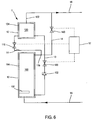
- the pipe element (11) is connected to the same draw point as the pipe element (14) (via a bifurcation point (11b)) , which allows the first tank (10) to have only two stitching points (for withdrawal) instead of three, thus reducing manufacturing costs.
- the first tank operates alone, the second tank being disconnected from the first tank.
- Cold water arrives from the water network via the cold water inlet (15) into the first tank (10). It is then heated by the heating device (102) and then injected into the hot water network via the pipe (14) towards the hot water outlet (16).
- the water heater device operates with the two tanks, the two tanks being connected via the pipes (11) and (13) and the first tank is disconnected from the hot water outlet (16) by closing the valve (140).
- the water enters the first tank (10) via the cold water inlet (15), and is heated by the heating device (102), goes up within the enclosure of the first tank (100) thanks to a thermosiphon effect, and rises via the pipe (11) into the chamber (120) of the second tank (12).
- This hot water injected into the second tank (12) pushes the cooled water in the time located in a lower part of the second tank via the pipe (13) to return to the chamber (100) of the first tank (10) at the level the lower part, that is to say the height where is located the heating device (102).
- the non-return valve (132) is provided. Thus, the hot water rises only through the pipe element (11).
- This opening and closing can be done manually or automatically through the computing unit (17), this computing unit tilting the water heater device in the first or second mode of operation according to the hot water requirements.
- Such a device thus makes it possible to achieve a balance between the real need and the production of domestic hot water, thus making it possible to make the water heater more efficient without sacrificing for all that the comfort of use of the hot water network.
- Such a method of renovating a hot water installation allows, at lower cost, to increase the available volume of the water heater device, while allowing the modularity of this available volume.
- This renovation is light compared to the original installation because it simply requires the installation of the second tank and additional pipe elements allowing the controlled circulation of water between the two tanks and the connection of the second tank to the exit of hot water and the arrangement of an additional valve between the first tank and the hot water outlet.
- a device as shown in figure 6 requires only two stitches instead of three, thus reducing the cost of development and renovations.
- thermosiphon effect it may be provided the installation of an additional pump in addition to the valve (110), to help the flow of water between the first tank (10) and the second tank (12).
Landscapes
- Engineering & Computer Science (AREA)
- Physics & Mathematics (AREA)
- Thermal Sciences (AREA)
- Chemical & Material Sciences (AREA)
- Combustion & Propulsion (AREA)
- Mechanical Engineering (AREA)
- General Engineering & Computer Science (AREA)
- Life Sciences & Earth Sciences (AREA)
- Sustainable Development (AREA)
- Sustainable Energy (AREA)
- Heat-Pump Type And Storage Water Heaters (AREA)
Claims (10)
- Warmwasserbereitervorrichtung, die einen Kaltwassereingang (15) und einen Warmwasserausgang (16) umfasst, wobei die Vorrichtung zwei getrennte und thermisch isolierte Behälter umfasst,- einen ersten Behälter (10), der zum Erhitzen und zur Speicherung von Wasser bestimmt ist und eine Heizvorrichtung (102) umfasst, wobei der erste Behälter mit dem Kaltwassereingang (15) und dem Warmwasserausgang (16) verbunden ist, und- einen zweiten Behälter (12), der zur Speicherung von warmem Wasser bestimmt ist und mit dem Warmwasserausgang (16) verbunden ist,wobei die Vorrichtung ferner erste Mittel (11, 13, 110, 130, 132) für den gesteuerten Umlauf von Wasser zwischen den zwei Behältern (10, 12) umfasst, die geeignet sind, den Umlauf von Wasser zwischen den zwei Behältern (10, 12) zu verhindern, und zweite Mittel (14, 140) für den gesteuerten Umlauf von Wasser zwischen dem ersten Behälter (10) und dem Warmwasserausgang (16) umfasst, derart, dass die ersten Mittel (11, 13, 110, 130, 132) für den gesteuerten Umlauf von Wasser zwischen den zwei Behältern (10, 12) gesteuerte Mittel (110, 130) umfassen, die zwischen zwei Zuständen geschaltet werden können:- dem einen, offenen, in dem das Wasser frei vom ersten (10) in Richtung des zweiten Behälters (12) und vom zweiten Behälter (12) in Richtung des ersten (10) umläuft;- dem anderen, geschlossenen, in dem der Umlauf von Wasser zwischen den zwei Behältern (10, 12) gesperrt ist,derart, dass der zweite Behälter (12) ein Zusatzbehälter ist, der einzig betriebsfähig ist, wenn die schaltbaren gesteuerten Mittel (110, 130) der ersten Mittel (11, 13, 110, 130, 132) für den gesteuerten Umlauf von Wasser sich im offenen Zustand befinden, wobei die Vorrichtung derart ist, dass die ersten Mittel (11, 13, 110, 130, 132) für den gesteuerten Umlauf von Wasser zwischen den zwei Behältern (10, 12) ein erstes Rohrleitungselement (11) umfassen, das einerseits mit einem hohen Pegel des ersten Behälters (10) verbunden ist und andererseits mit einem niedrigen Pegel des zweiten Behälters (12) verbunden ist, und wobei die ersten Mittel für den gesteuerten Umlauf von Wasser (11, 13, 110, 130, 132) zwischen den zwei Behältern ein zweites Rohrleitungselement (13) umfassen, wobei die Vorrichtung dadurch gekennzeichnet ist, dass das zweite Rohrleitungselement (13) einerseits mit einem niedrigen Pegel des ersten Behälters (10) und andererseits mit einem niedrigen Pegel des zweiten Behälters (12) verbunden ist.
- Vorrichtung nach Anspruch 1, wobei die zweiten Mittel (14, 140) für den gesteuerten Umlauf von Wasser zwischen dem ersten Behälter (10) und dem Warmwasserausgang (16) ein gesteuertes Mittel (140) umfassen, das zwischen zwei Zuständen geschaltet werden kann:- dem einen, offenen, wenn die schaltbaren gesteuerten Mittel (110, 130) der ersten Mittel (11, 13, 110, 130, 132) für den gesteuerten Umlauf von Wasser geschlossen sind, wobei in diesem Zustand das Wasser frei zwischen dem ersten Behälter (10) und dem Warmwasserausgang (16) umläuft, und- dem anderen, geschlossenen, wenn die schaltbaren gesteuerten Mittel (110, 130) der ersten Mittel (11, 13, 110, 130, 132) für den gesteuerten Umlauf von Wasser offen sind, wobei in diesem Zustand der Umlauf von Wasser zwischen dem ersten Behälter (10) und dem Warmwasserausgang (16) gesperrt ist.
- Vorrichtung nach Anspruch 1 oder 2, wobei das Wasser des Warmwasserausgangs (16) abgelassen wird:- einzig im Bereich des zweiten Behälters (12) im offenen Zustand der schaltbaren gesteuerten Mittel (110, 130) der ersten Mittel (11, 13, 110, 130, 132) für den gesteuerten Umlauf von Wasser,- einzig im Bereich des ersten Behälters (10) im geschlossenen Zustand der schaltbaren gesteuerten Mittel (110, 130) der ersten Mittel (11, 13, 110, 130, 132) für den gesteuerten Umlauf von Wasser.
- Vorrichtung nach einem der vorhergehenden Ansprüche, wobei der zweite Behälter (12) kein inneres Heizmittel umfasst.
- Vorrichtung nach einem der vorhergehenden Ansprüche, wobei das Rohrleitungselement (13), das einerseits mit einem niedrigen Pegel des ersten Behälters (10) und andererseits mit einem niedrigen Pegel des zweiten Behälters (12) verbunden ist, ferner ein Mittel zum Verhindern des Umlaufs von Wasser (132) von dem ersten Behälter (10) in Richtung des zweiten Behälters (12) umfasst.
- Vorrichtung nach einem der vorhergehenden Ansprüche, wobei das zweite Mittel (14; 140) für den gesteuerten Umlauf von Wasser zwischen dem ersten Behälter (10) und dem Warmwasserausgang (16) ein drittes Rohrleitungselement (14) umfasst, das einerseits mit einem hohen Pegel des ersten Behälters (10) und andererseits mit dem Warmwasserausgang (16) verbunden ist.
- Vorrichtung nach einem der vorhergehenden Ansprüche, wobei die ersten und die zweiten Mittel für den gesteuerten Umlauf ein oder mehrere Ventile (110, 130, 140) umfassen.
- Verfahren zur Verwendung einer Warmwasserbereitervorrichtung nach einem der vorhergehenden Ansprüche, dadurch gekennzeichnet, dass es die folgenden Schritte umfasst:- Gewährleisten der Verbindungen zwischen den zwei Behältern mittels erster Mittel (11, 13, 110, 130, 132) für den gesteuerten Umlauf von Wasser zwischen den zwei Behältern (10, 12), die ein erstes Rohrleitungselement (11), das einerseits mit einem hohen Pegel des ersten Behälters (10) und andererseits mit einem niedrigen Pegel des zweiten Behälters (12) verbunden ist, und ein zweites Rohrleitungselement (13) umfassen, das einerseits mit einem niedrigen Pegel des ersten Behälters (10) und andererseits mit einem niedrigen Pegel des zweiten Behälters (12) verbunden ist,- Verhindern des Umlaufs von Wasser zwischen den zwei Behältern (10, 12),- Zulassen des Umlaufs zwischen dem ersten Behälter (10) und dem Warmwasserausgang (16).
- Verfahren zur Verwendung einer Warmwasserbereitervorrichtung nach einem der Ansprüche 1 bis 8, dadurch gekennzeichnet, dass es die folgenden Schritte umfasst:- Gewährleistung der Verbindungen zwischen den zwei Behältern mittels erster Mittel (11, 13, 110, 130, 132) für den gesteuerten Umlauf von Wasser zwischen den zwei Behältern (10, 12), die ein erstes Rohrleitungselement (11), das einerseits mit einem hohen Pegel des ersten Behälters (10) und andererseits mit einem niedrigen Pegel des zweiten Behälters (12) verbunden ist, und ein zweites Rohrleitungselement (13) umfassen, das einerseits mit einem niedrigen Pegel des ersten Behälters (10) und andererseits mit einem niedrigen Pegel des zweiten Behälters (12) verbunden ist,- Zulassen des Umlaufs von Wasser zwischen den zwei Behältern (10, 12),- Verhindern des Umlaufs zwischen dem ersten Behälter (10) und dem Warmwasserausgang (16).
- Verfahren zur Erneuerung einer bestehenden Warmwasserbereitervorrichtung, wobei der bestehende Warmwasserbereiter einen ersten Behälter (10) umfasst, der thermisch von der Erhitzung und der Speicherung von Wasser isoliert ist, die eine Heizvorrichtung umfasst, und einerseits mit einem Kaltwassereingang (15) und andererseits mit einem Warmwasserausgang (16) verbunden ist, wobei das Verfahren die folgenden Schritte umfasst:- Liefern eines zweiten Behälters (12), der von dem ersten Behälter (10) getrennt und thermisch isoliert ist,- Anordnen der zweiten Mittel (140) für den gesteuerten Umlauf von Wasser zwischen dem ersten Behälter (10) und dem Warmwasserausgang (16),- Verbinden des zweiten Behälters (12) mit dem Warmwasserausgang (16),dadurch gekennzeichnet, dass das Verfahren den folgenden Schritt umfasst:- Anordnen der ersten Mittel (11, 13, 110, 130, 132) für den gesteuerten Umlauf von Wasser zwischen den zwei Behältern (10, 12), wobei die ersten Mittel (11, 13, 110, 130, 132) für den gesteuerten Umlauf von Wasser zwischen den zwei Behältern (10, 12) gesteuerte Mittel (110, 130) umfassen, die zwischen zwei Zuständen geschaltet werden können:- dem einen, offenen, in dem das Wasser frei vom ersten (10) in Richtung des zweiten Behälters (12) und vom zweiten Behälter (12) in Richtung des ersten (10) umläuft;- dem anderen, geschlossenen, in dem der Umlauf von Wasser zwischen den zwei Behältern (10, 12) gesperrt ist,derart, dass der zweite Behälter (12) ein Zusatzbehälter ist, der einzig betriebsfähig ist, wenn die schaltbaren Mittel (110, 130) der ersten Mittel (11, 13, 110, 130, 132) für den gesteuerten Umlauf von Wasser sich im offenen Zustand befinden, und die ersten Mittel (11, 13, 110, 130, 132) für den gesteuerten Umlauf von Wasser zwischen den zwei Behältern (10, 12) ein erstes Kanalisationselement (11), das einerseits mit einem hohen Pegel des ersten Behälters (10) und andererseits mit einem niedrigen Pegel des zweiten Behälters (12) verbunden ist, und ein zweites Kanalisationselement (13) umfassen, das einerseits mit einem niedrigen Pegel des ersten Behälters (10) und andererseits mit einem niedrigen Pegel des zweiten Behälters (12) verbunden ist.
Applications Claiming Priority (1)
| Application Number | Priority Date | Filing Date | Title |
|---|---|---|---|
| FR0952389A FR2944342B1 (fr) | 2009-04-10 | 2009-04-10 | Dispositif de chauffe-eau a volume variable ameliore |
Publications (2)
| Publication Number | Publication Date |
|---|---|
| EP2241828A1 EP2241828A1 (de) | 2010-10-20 |
| EP2241828B1 true EP2241828B1 (de) | 2016-03-30 |
Family
ID=41278671
Family Applications (1)
| Application Number | Title | Priority Date | Filing Date |
|---|---|---|---|
| EP10159658.3A Not-in-force EP2241828B1 (de) | 2009-04-10 | 2010-04-12 | verbesserte Warmwasseranlage mit variablem Volumen |
Country Status (2)
| Country | Link |
|---|---|
| EP (1) | EP2241828B1 (de) |
| FR (1) | FR2944342B1 (de) |
Family Cites Families (3)
| Publication number | Priority date | Publication date | Assignee | Title |
|---|---|---|---|---|
| FR2332505A1 (fr) * | 1975-11-18 | 1977-06-17 | Cerca | Procede et appareillage pour la preparation d'eau chaude a partir de l'energie solaire |
| US4568821A (en) * | 1982-06-22 | 1986-02-04 | Pba Inc. | Remote water heater controller |
| GB0620262D0 (en) * | 2006-10-13 | 2006-11-22 | Willis Heating & Plumbing Co L | A water heating system |
-
2009
- 2009-04-10 FR FR0952389A patent/FR2944342B1/fr not_active Expired - Fee Related
-
2010
- 2010-04-12 EP EP10159658.3A patent/EP2241828B1/de not_active Not-in-force
Also Published As
| Publication number | Publication date |
|---|---|
| FR2944342A1 (fr) | 2010-10-15 |
| EP2241828A1 (de) | 2010-10-20 |
| FR2944342B1 (fr) | 2013-07-05 |
Similar Documents
| Publication | Publication Date | Title |
|---|---|---|
| EP2894419B1 (de) | Klimaanlagenvorrichtung eines Abteils, insbesondere für Schienenfahrzeug, und Verfahren zum Auftauen des Geräts | |
| EP2191206A2 (de) | Erwärmungs- und kühlungsanlage mit einer wärmepumpe und einem an mehrere wärmesammlungs- und verteilungsleitungen gekoppelten kasten zur verteilung einer wärmeübertragungsflüssigkeit | |
| FR2505990A1 (fr) | Systeme de chauffage pour locaux, notamment pour locaux d'habitation | |
| WO2014044864A1 (fr) | Installation de chauffe-eau sanitaire à fonction de chauffage | |
| EP0493210B1 (de) | Solar-Wärmespeicher und Anlage zur Kühlung und Klimatisierung oder Seewasserentsalzung | |
| EP3225922B1 (de) | Kühl-, klimatisierungs- oder heizsystem | |
| FR2537250A1 (fr) | Procede et dispositif de chauffage de liquides | |
| EP2241828A1 (de) | Verbesserte Warmwasseranlage mit variablem Volumen | |
| EP2366845B1 (de) | Aktives Wärmedämmungsverfahren und Vorrichtung zur Umsetzung dieses Verfahrens | |
| FR2851644A1 (fr) | Installation solaire combinee comportant des moyens de gestion des surchauffes et procede de controle de l'installation | |
| EP2354714B1 (de) | Solarwärmesystem und Verfahren zum Beheizen eines Wohnraums | |
| EP3139100B1 (de) | Anlage und verfahren zur warmwassererzeugung | |
| WO2013093246A1 (fr) | Procédé de gestion d'un système de pompe à chaleur, système de pompe à chaleur, et installation de chauffage comprenant un tel système | |
| FR3036174A1 (fr) | Dispositif de stockage geothermique reversible dans un massif de sol reconstitue | |
| CH701001A2 (fr) | Citerne solaire. | |
| WO2021110791A1 (fr) | Systeme de distribution d'eau | |
| WO2020016489A1 (fr) | Systeme de chauffage d'eau a prechauffage par energie renouvelable avec complement par chauffage instantane | |
| FR3088990A1 (fr) | Installation de chauffage | |
| EP2655977B1 (de) | Vorrichtung zur erzeugung vom sanitärwarmwasser durch die verwendung von thermischen solarkollektoren mit wasser als betriebsflüssigkeit, die direkt mit einem warwasserspeicher verbunden sind. | |
| EP2354712A1 (de) | Solarwärmekollektor, Solarwärmesystem, das einen solchen Solarwärmekollektor umfasst, und entsprechendes Heizverfahren eines Wohnraums | |
| EP4562351A1 (de) | Kit zur anpassung eines zentralheizungssystems und verfahren zur steuerung eines mit solch einem kit ausgestatteten systems | |
| EP3032180B1 (de) | Thermische Vorrichtung und Einsatzverfahren einer solchen Vorrichtung | |
| WO2008113727A1 (fr) | Dispositif de couplage d'un système de chauffage à liquide caloporteur à un dispositif de refroidissement | |
| FR3002027A1 (fr) | Chauffage solaire integral | |
| FR2858047A1 (fr) | Systeme de chauffage destine a chauffer ou rafraichir une piece et batiment comprenant ce systeme de chauffage |
Legal Events
| Date | Code | Title | Description |
|---|---|---|---|
| PUAI | Public reference made under article 153(3) epc to a published international application that has entered the european phase |
Free format text: ORIGINAL CODE: 0009012 |
|
| 17P | Request for examination filed |
Effective date: 20100412 |
|
| AK | Designated contracting states |
Kind code of ref document: A1 Designated state(s): AT BE BG CH CY CZ DE DK EE ES FI FR GB GR HR HU IE IS IT LI LT LU LV MC MK MT NL NO PL PT RO SE SI SK SM TR |
|
| AX | Request for extension of the european patent |
Extension state: AL BA ME RS |
|
| 17Q | First examination report despatched |
Effective date: 20150121 |
|
| GRAP | Despatch of communication of intention to grant a patent |
Free format text: ORIGINAL CODE: EPIDOSNIGR1 |
|
| INTG | Intention to grant announced |
Effective date: 20151002 |
|
| GRAS | Grant fee paid |
Free format text: ORIGINAL CODE: EPIDOSNIGR3 |
|
| INTG | Intention to grant announced |
Effective date: 20160129 |
|
| GRAA | (expected) grant |
Free format text: ORIGINAL CODE: 0009210 |
|
| AK | Designated contracting states |
Kind code of ref document: B1 Designated state(s): AT BE BG CH CY CZ DE DK EE ES FI FR GB GR HR HU IE IS IT LI LT LU LV MC MK MT NL NO PL PT RO SE SI SK SM TR |
|
| REG | Reference to a national code |
Ref country code: GB Ref legal event code: FG4D Free format text: NOT ENGLISH |
|
| REG | Reference to a national code |
Ref country code: CH Ref legal event code: EP |
|
| REG | Reference to a national code |
Ref country code: AT Ref legal event code: REF Ref document number: 785828 Country of ref document: AT Kind code of ref document: T Effective date: 20160415 |
|
| REG | Reference to a national code |
Ref country code: IE Ref legal event code: FG4D Free format text: LANGUAGE OF EP DOCUMENT: FRENCH |
|
| REG | Reference to a national code |
Ref country code: DE Ref legal event code: R096 Ref document number: 602010031575 Country of ref document: DE |
|
| REG | Reference to a national code |
Ref country code: FR Ref legal event code: PLFP Year of fee payment: 7 |
|
| REG | Reference to a national code |
Ref country code: LT Ref legal event code: MG4D |
|
| PG25 | Lapsed in a contracting state [announced via postgrant information from national office to epo] |
Ref country code: GR Free format text: LAPSE BECAUSE OF FAILURE TO SUBMIT A TRANSLATION OF THE DESCRIPTION OR TO PAY THE FEE WITHIN THE PRESCRIBED TIME-LIMIT Effective date: 20160701 Ref country code: FI Free format text: LAPSE BECAUSE OF FAILURE TO SUBMIT A TRANSLATION OF THE DESCRIPTION OR TO PAY THE FEE WITHIN THE PRESCRIBED TIME-LIMIT Effective date: 20160330 Ref country code: NO Free format text: LAPSE BECAUSE OF FAILURE TO SUBMIT A TRANSLATION OF THE DESCRIPTION OR TO PAY THE FEE WITHIN THE PRESCRIBED TIME-LIMIT Effective date: 20160630 Ref country code: HR Free format text: LAPSE BECAUSE OF FAILURE TO SUBMIT A TRANSLATION OF THE DESCRIPTION OR TO PAY THE FEE WITHIN THE PRESCRIBED TIME-LIMIT Effective date: 20160330 |
|
| REG | Reference to a national code |
Ref country code: NL Ref legal event code: MP Effective date: 20160330 |
|
| REG | Reference to a national code |
Ref country code: AT Ref legal event code: MK05 Ref document number: 785828 Country of ref document: AT Kind code of ref document: T Effective date: 20160330 |
|
| PG25 | Lapsed in a contracting state [announced via postgrant information from national office to epo] |
Ref country code: BE Free format text: LAPSE BECAUSE OF NON-PAYMENT OF DUE FEES Effective date: 20160430 Ref country code: LT Free format text: LAPSE BECAUSE OF FAILURE TO SUBMIT A TRANSLATION OF THE DESCRIPTION OR TO PAY THE FEE WITHIN THE PRESCRIBED TIME-LIMIT Effective date: 20160330 Ref country code: LV Free format text: LAPSE BECAUSE OF FAILURE TO SUBMIT A TRANSLATION OF THE DESCRIPTION OR TO PAY THE FEE WITHIN THE PRESCRIBED TIME-LIMIT Effective date: 20160330 Ref country code: SE Free format text: LAPSE BECAUSE OF FAILURE TO SUBMIT A TRANSLATION OF THE DESCRIPTION OR TO PAY THE FEE WITHIN THE PRESCRIBED TIME-LIMIT Effective date: 20160330 |
|
| PG25 | Lapsed in a contracting state [announced via postgrant information from national office to epo] |
Ref country code: NL Free format text: LAPSE BECAUSE OF FAILURE TO SUBMIT A TRANSLATION OF THE DESCRIPTION OR TO PAY THE FEE WITHIN THE PRESCRIBED TIME-LIMIT Effective date: 20160330 |
|
| PG25 | Lapsed in a contracting state [announced via postgrant information from national office to epo] |
Ref country code: PL Free format text: LAPSE BECAUSE OF FAILURE TO SUBMIT A TRANSLATION OF THE DESCRIPTION OR TO PAY THE FEE WITHIN THE PRESCRIBED TIME-LIMIT Effective date: 20160330 Ref country code: EE Free format text: LAPSE BECAUSE OF FAILURE TO SUBMIT A TRANSLATION OF THE DESCRIPTION OR TO PAY THE FEE WITHIN THE PRESCRIBED TIME-LIMIT Effective date: 20160330 Ref country code: IS Free format text: LAPSE BECAUSE OF FAILURE TO SUBMIT A TRANSLATION OF THE DESCRIPTION OR TO PAY THE FEE WITHIN THE PRESCRIBED TIME-LIMIT Effective date: 20160730 |
|
| REG | Reference to a national code |
Ref country code: DE Ref legal event code: R119 Ref document number: 602010031575 Country of ref document: DE |
|
| PG25 | Lapsed in a contracting state [announced via postgrant information from national office to epo] |
Ref country code: ES Free format text: LAPSE BECAUSE OF FAILURE TO SUBMIT A TRANSLATION OF THE DESCRIPTION OR TO PAY THE FEE WITHIN THE PRESCRIBED TIME-LIMIT Effective date: 20160330 Ref country code: SM Free format text: LAPSE BECAUSE OF FAILURE TO SUBMIT A TRANSLATION OF THE DESCRIPTION OR TO PAY THE FEE WITHIN THE PRESCRIBED TIME-LIMIT Effective date: 20160330 Ref country code: AT Free format text: LAPSE BECAUSE OF FAILURE TO SUBMIT A TRANSLATION OF THE DESCRIPTION OR TO PAY THE FEE WITHIN THE PRESCRIBED TIME-LIMIT Effective date: 20160330 Ref country code: CZ Free format text: LAPSE BECAUSE OF FAILURE TO SUBMIT A TRANSLATION OF THE DESCRIPTION OR TO PAY THE FEE WITHIN THE PRESCRIBED TIME-LIMIT Effective date: 20160330 Ref country code: SK Free format text: LAPSE BECAUSE OF FAILURE TO SUBMIT A TRANSLATION OF THE DESCRIPTION OR TO PAY THE FEE WITHIN THE PRESCRIBED TIME-LIMIT Effective date: 20160330 Ref country code: RO Free format text: LAPSE BECAUSE OF FAILURE TO SUBMIT A TRANSLATION OF THE DESCRIPTION OR TO PAY THE FEE WITHIN THE PRESCRIBED TIME-LIMIT Effective date: 20160330 Ref country code: PT Free format text: LAPSE BECAUSE OF FAILURE TO SUBMIT A TRANSLATION OF THE DESCRIPTION OR TO PAY THE FEE WITHIN THE PRESCRIBED TIME-LIMIT Effective date: 20160801 |
|
| REG | Reference to a national code |
Ref country code: CH Ref legal event code: PL |
|
| PG25 | Lapsed in a contracting state [announced via postgrant information from national office to epo] |
Ref country code: IT Free format text: LAPSE BECAUSE OF FAILURE TO SUBMIT A TRANSLATION OF THE DESCRIPTION OR TO PAY THE FEE WITHIN THE PRESCRIBED TIME-LIMIT Effective date: 20160330 |
|
| REG | Reference to a national code |
Ref country code: IE Ref legal event code: MM4A |
|
| PG25 | Lapsed in a contracting state [announced via postgrant information from national office to epo] |
Ref country code: LI Free format text: LAPSE BECAUSE OF NON-PAYMENT OF DUE FEES Effective date: 20160430 Ref country code: CH Free format text: LAPSE BECAUSE OF NON-PAYMENT OF DUE FEES Effective date: 20160430 Ref country code: DE Free format text: LAPSE BECAUSE OF NON-PAYMENT OF DUE FEES Effective date: 20161101 Ref country code: DK Free format text: LAPSE BECAUSE OF FAILURE TO SUBMIT A TRANSLATION OF THE DESCRIPTION OR TO PAY THE FEE WITHIN THE PRESCRIBED TIME-LIMIT Effective date: 20160330 |
|
| PLBE | No opposition filed within time limit |
Free format text: ORIGINAL CODE: 0009261 |
|
| STAA | Information on the status of an ep patent application or granted ep patent |
Free format text: STATUS: NO OPPOSITION FILED WITHIN TIME LIMIT |
|
| GBPC | Gb: european patent ceased through non-payment of renewal fee |
Effective date: 20160630 |
|
| 26N | No opposition filed |
Effective date: 20170103 |
|
| REG | Reference to a national code |
Ref country code: FR Ref legal event code: PLFP Year of fee payment: 8 |
|
| PG25 | Lapsed in a contracting state [announced via postgrant information from national office to epo] |
Ref country code: SI Free format text: LAPSE BECAUSE OF FAILURE TO SUBMIT A TRANSLATION OF THE DESCRIPTION OR TO PAY THE FEE WITHIN THE PRESCRIBED TIME-LIMIT Effective date: 20160330 Ref country code: GB Free format text: LAPSE BECAUSE OF NON-PAYMENT OF DUE FEES Effective date: 20160630 Ref country code: IE Free format text: LAPSE BECAUSE OF NON-PAYMENT OF DUE FEES Effective date: 20160412 |
|
| REG | Reference to a national code |
Ref country code: FR Ref legal event code: PLFP Year of fee payment: 9 |
|
| PG25 | Lapsed in a contracting state [announced via postgrant information from national office to epo] |
Ref country code: HU Free format text: LAPSE BECAUSE OF FAILURE TO SUBMIT A TRANSLATION OF THE DESCRIPTION OR TO PAY THE FEE WITHIN THE PRESCRIBED TIME-LIMIT; INVALID AB INITIO Effective date: 20100412 Ref country code: CY Free format text: LAPSE BECAUSE OF FAILURE TO SUBMIT A TRANSLATION OF THE DESCRIPTION OR TO PAY THE FEE WITHIN THE PRESCRIBED TIME-LIMIT Effective date: 20160330 |
|
| PG25 | Lapsed in a contracting state [announced via postgrant information from national office to epo] |
Ref country code: LU Free format text: LAPSE BECAUSE OF NON-PAYMENT OF DUE FEES Effective date: 20160412 Ref country code: MK Free format text: LAPSE BECAUSE OF FAILURE TO SUBMIT A TRANSLATION OF THE DESCRIPTION OR TO PAY THE FEE WITHIN THE PRESCRIBED TIME-LIMIT Effective date: 20160330 Ref country code: TR Free format text: LAPSE BECAUSE OF FAILURE TO SUBMIT A TRANSLATION OF THE DESCRIPTION OR TO PAY THE FEE WITHIN THE PRESCRIBED TIME-LIMIT Effective date: 20160330 Ref country code: MT Free format text: LAPSE BECAUSE OF FAILURE TO SUBMIT A TRANSLATION OF THE DESCRIPTION OR TO PAY THE FEE WITHIN THE PRESCRIBED TIME-LIMIT Effective date: 20160330 Ref country code: MC Free format text: LAPSE BECAUSE OF FAILURE TO SUBMIT A TRANSLATION OF THE DESCRIPTION OR TO PAY THE FEE WITHIN THE PRESCRIBED TIME-LIMIT Effective date: 20160330 |
|
| PG25 | Lapsed in a contracting state [announced via postgrant information from national office to epo] |
Ref country code: BG Free format text: LAPSE BECAUSE OF FAILURE TO SUBMIT A TRANSLATION OF THE DESCRIPTION OR TO PAY THE FEE WITHIN THE PRESCRIBED TIME-LIMIT Effective date: 20160330 |
|
| PGFP | Annual fee paid to national office [announced via postgrant information from national office to epo] |
Ref country code: FR Payment date: 20210427 Year of fee payment: 12 |
|
| PG25 | Lapsed in a contracting state [announced via postgrant information from national office to epo] |
Ref country code: FR Free format text: LAPSE BECAUSE OF NON-PAYMENT OF DUE FEES Effective date: 20220430 |