EP3032180B1 - Thermische Vorrichtung und Einsatzverfahren einer solchen Vorrichtung - Google Patents
Thermische Vorrichtung und Einsatzverfahren einer solchen Vorrichtung Download PDFInfo
- Publication number
- EP3032180B1 EP3032180B1 EP14197109.3A EP14197109A EP3032180B1 EP 3032180 B1 EP3032180 B1 EP 3032180B1 EP 14197109 A EP14197109 A EP 14197109A EP 3032180 B1 EP3032180 B1 EP 3032180B1
- Authority
- EP
- European Patent Office
- Prior art keywords
- heat
- transfer fluid
- collector
- heat transfer
- pump
- Prior art date
- Legal status (The legal status is an assumption and is not a legal conclusion. Google has not performed a legal analysis and makes no representation as to the accuracy of the status listed.)
- Active
Links
Images


Classifications
-
- F—MECHANICAL ENGINEERING; LIGHTING; HEATING; WEAPONS; BLASTING
- F24—HEATING; RANGES; VENTILATING
- F24D—DOMESTIC- OR SPACE-HEATING SYSTEMS, e.g. CENTRAL HEATING SYSTEMS; DOMESTIC HOT-WATER SUPPLY SYSTEMS; ELEMENTS OR COMPONENTS THEREFOR
- F24D3/00—Hot-water central heating systems
- F24D3/18—Hot-water central heating systems using heat pumps
-
- F—MECHANICAL ENGINEERING; LIGHTING; HEATING; WEAPONS; BLASTING
- F24—HEATING; RANGES; VENTILATING
- F24D—DOMESTIC- OR SPACE-HEATING SYSTEMS, e.g. CENTRAL HEATING SYSTEMS; DOMESTIC HOT-WATER SUPPLY SYSTEMS; ELEMENTS OR COMPONENTS THEREFOR
- F24D17/00—Domestic hot-water supply systems
- F24D17/02—Domestic hot-water supply systems using heat pumps
-
- F—MECHANICAL ENGINEERING; LIGHTING; HEATING; WEAPONS; BLASTING
- F24—HEATING; RANGES; VENTILATING
- F24D—DOMESTIC- OR SPACE-HEATING SYSTEMS, e.g. CENTRAL HEATING SYSTEMS; DOMESTIC HOT-WATER SUPPLY SYSTEMS; ELEMENTS OR COMPONENTS THEREFOR
- F24D19/00—Details
- F24D19/10—Arrangement or mounting of control or safety devices
- F24D19/1006—Arrangement or mounting of control or safety devices for water heating systems
- F24D19/1009—Arrangement or mounting of control or safety devices for water heating systems for central heating
- F24D19/1045—Arrangement or mounting of control or safety devices for water heating systems for central heating the system uses a heat pump and solar energy
-
- F—MECHANICAL ENGINEERING; LIGHTING; HEATING; WEAPONS; BLASTING
- F24—HEATING; RANGES; VENTILATING
- F24D—DOMESTIC- OR SPACE-HEATING SYSTEMS, e.g. CENTRAL HEATING SYSTEMS; DOMESTIC HOT-WATER SUPPLY SYSTEMS; ELEMENTS OR COMPONENTS THEREFOR
- F24D19/00—Details
- F24D19/10—Arrangement or mounting of control or safety devices
- F24D19/1006—Arrangement or mounting of control or safety devices for water heating systems
- F24D19/1051—Arrangement or mounting of control or safety devices for water heating systems for domestic hot water
- F24D19/106—Arrangement or mounting of control or safety devices for water heating systems for domestic hot water the system uses a heat pump and solar energy
-
- F—MECHANICAL ENGINEERING; LIGHTING; HEATING; WEAPONS; BLASTING
- F24—HEATING; RANGES; VENTILATING
- F24F—AIR-CONDITIONING; AIR-HUMIDIFICATION; VENTILATION; USE OF AIR CURRENTS FOR SCREENING
- F24F5/00—Air-conditioning systems or apparatus not covered by F24F1/00 or F24F3/00, e.g. using solar heat or combined with household units such as an oven or water heater
- F24F5/0046—Air-conditioning systems or apparatus not covered by F24F1/00 or F24F3/00, e.g. using solar heat or combined with household units such as an oven or water heater using natural energy, e.g. solar energy, energy from the ground
-
- F—MECHANICAL ENGINEERING; LIGHTING; HEATING; WEAPONS; BLASTING
- F24—HEATING; RANGES; VENTILATING
- F24D—DOMESTIC- OR SPACE-HEATING SYSTEMS, e.g. CENTRAL HEATING SYSTEMS; DOMESTIC HOT-WATER SUPPLY SYSTEMS; ELEMENTS OR COMPONENTS THEREFOR
- F24D2200/00—Heat sources or energy sources
- F24D2200/11—Geothermal energy
-
- F—MECHANICAL ENGINEERING; LIGHTING; HEATING; WEAPONS; BLASTING
- F24—HEATING; RANGES; VENTILATING
- F24D—DOMESTIC- OR SPACE-HEATING SYSTEMS, e.g. CENTRAL HEATING SYSTEMS; DOMESTIC HOT-WATER SUPPLY SYSTEMS; ELEMENTS OR COMPONENTS THEREFOR
- F24D2200/00—Heat sources or energy sources
- F24D2200/12—Heat pump
- F24D2200/123—Compression type heat pumps
-
- F—MECHANICAL ENGINEERING; LIGHTING; HEATING; WEAPONS; BLASTING
- F24—HEATING; RANGES; VENTILATING
- F24D—DOMESTIC- OR SPACE-HEATING SYSTEMS, e.g. CENTRAL HEATING SYSTEMS; DOMESTIC HOT-WATER SUPPLY SYSTEMS; ELEMENTS OR COMPONENTS THEREFOR
- F24D2200/00—Heat sources or energy sources
- F24D2200/14—Solar energy
-
- F—MECHANICAL ENGINEERING; LIGHTING; HEATING; WEAPONS; BLASTING
- F25—REFRIGERATION OR COOLING; COMBINED HEATING AND REFRIGERATION SYSTEMS; HEAT PUMP SYSTEMS; MANUFACTURE OR STORAGE OF ICE; LIQUEFACTION SOLIDIFICATION OF GASES
- F25B—REFRIGERATION MACHINES, PLANTS OR SYSTEMS; COMBINED HEATING AND REFRIGERATION SYSTEMS; HEAT PUMP SYSTEMS
- F25B30/00—Heat pumps
- F25B30/02—Heat pumps of the compression type
-
- Y—GENERAL TAGGING OF NEW TECHNOLOGICAL DEVELOPMENTS; GENERAL TAGGING OF CROSS-SECTIONAL TECHNOLOGIES SPANNING OVER SEVERAL SECTIONS OF THE IPC; TECHNICAL SUBJECTS COVERED BY FORMER USPC CROSS-REFERENCE ART COLLECTIONS [XRACs] AND DIGESTS
- Y02—TECHNOLOGIES OR APPLICATIONS FOR MITIGATION OR ADAPTATION AGAINST CLIMATE CHANGE
- Y02B—CLIMATE CHANGE MITIGATION TECHNOLOGIES RELATED TO BUILDINGS, e.g. HOUSING, HOUSE APPLIANCES OR RELATED END-USER APPLICATIONS
- Y02B10/00—Integration of renewable energy sources in buildings
- Y02B10/20—Solar thermal
-
- Y—GENERAL TAGGING OF NEW TECHNOLOGICAL DEVELOPMENTS; GENERAL TAGGING OF CROSS-SECTIONAL TECHNOLOGIES SPANNING OVER SEVERAL SECTIONS OF THE IPC; TECHNICAL SUBJECTS COVERED BY FORMER USPC CROSS-REFERENCE ART COLLECTIONS [XRACs] AND DIGESTS
- Y02—TECHNOLOGIES OR APPLICATIONS FOR MITIGATION OR ADAPTATION AGAINST CLIMATE CHANGE
- Y02B—CLIMATE CHANGE MITIGATION TECHNOLOGIES RELATED TO BUILDINGS, e.g. HOUSING, HOUSE APPLIANCES OR RELATED END-USER APPLICATIONS
- Y02B10/00—Integration of renewable energy sources in buildings
- Y02B10/40—Geothermal heat-pumps
-
- Y—GENERAL TAGGING OF NEW TECHNOLOGICAL DEVELOPMENTS; GENERAL TAGGING OF CROSS-SECTIONAL TECHNOLOGIES SPANNING OVER SEVERAL SECTIONS OF THE IPC; TECHNICAL SUBJECTS COVERED BY FORMER USPC CROSS-REFERENCE ART COLLECTIONS [XRACs] AND DIGESTS
- Y02—TECHNOLOGIES OR APPLICATIONS FOR MITIGATION OR ADAPTATION AGAINST CLIMATE CHANGE
- Y02B—CLIMATE CHANGE MITIGATION TECHNOLOGIES RELATED TO BUILDINGS, e.g. HOUSING, HOUSE APPLIANCES OR RELATED END-USER APPLICATIONS
- Y02B10/00—Integration of renewable energy sources in buildings
- Y02B10/70—Hybrid systems, e.g. uninterruptible or back-up power supplies integrating renewable energies
-
- Y—GENERAL TAGGING OF NEW TECHNOLOGICAL DEVELOPMENTS; GENERAL TAGGING OF CROSS-SECTIONAL TECHNOLOGIES SPANNING OVER SEVERAL SECTIONS OF THE IPC; TECHNICAL SUBJECTS COVERED BY FORMER USPC CROSS-REFERENCE ART COLLECTIONS [XRACs] AND DIGESTS
- Y02—TECHNOLOGIES OR APPLICATIONS FOR MITIGATION OR ADAPTATION AGAINST CLIMATE CHANGE
- Y02B—CLIMATE CHANGE MITIGATION TECHNOLOGIES RELATED TO BUILDINGS, e.g. HOUSING, HOUSE APPLIANCES OR RELATED END-USER APPLICATIONS
- Y02B30/00—Energy efficient heating, ventilation or air conditioning [HVAC]
- Y02B30/12—Hot water central heating systems using heat pumps
Definitions
- the invention relates to a thermal device for a heating installation, domestic hot water production and / or air conditioning.
- a thermal device comprising a geothermal heat pump (or PAC) based on the arrangement of thermal sensors in the ground and on the circulation, between the heat pump and these sensors, a heat transfer fluid allowing the transfer of the calories captured by the sensors to the heat pump.
- PAC geothermal heat pump
- thermal devices with a supplementary heat source, such as for example an aerosol device or heat recovery from greywater, and also to circulate the fluid therein. coolant.
- a supplementary heat source such as for example an aerosol device or heat recovery from greywater
- the heat pump, the buried sensors and the booster source are arranged in series within the circuit and are traversed by the heat transfer fluid in this order.
- This configuration makes it possible to increase the heat recovery by the circuit in particular circumstances, for example in which the soil in which the sensors are buried is at a low temperature.
- this configuration also has a disadvantage.
- the document GB 2505655 A discloses a thermal device according to the preamble of claim 1.
- the passage of the heat transfer fluid by the buried sensor does not provide enough heat to the heat transfer fluid for the heat pump to operate in good conditions.
- the invention improves the situation.
- the invention relates to a thermal device for a heating installation, and / or production of domestic hot water and / or air conditioning, as defined in claim 1.
- the circulation means are adapted to circulate the heat transfer fluid within the heat collection circuit in a sequence according to which, once the coolant exits the heat pump, said coolant passes first into the heat transfer fluid. booster heat source then in the buried sensor.
- the coolant passes first through the backup source and then into the buried sensors.
- the passage of the fluid in the auxiliary source and in the buried sensors maximizes the recovery of thermal energy by the capture circuit.
- this sequence reduces the probability of occurrence of situations in which the heat transfer fluid temperature at the inlet of the heat pump is too low for the heat pump to operate with good performance.
- the circulation means are also adapted to circulate the heat transfer fluid within the heat capture circuit according to a second sequence according to which once the coolant exits the heat pump, said fluid coolant passes first into the buried sensor and then into the auxiliary heat source.
- This characteristic of the circulation means makes it possible to adapt the direction of circulation of the coolant to the conditions, in particular of the temperature of the ground in which the sensors are buried, which makes it possible to optimize the efficiency of the device.
- the circulation means comprise first, second and third selectively activatable circulation branches, the first circulation branch thermally connecting a first point of the sensing circuit arranged between an output of the pump. heat and an input of the auxiliary heat source to an input of the buried sensor, the second circulation branch thermally connecting an output of the buried sensor to a second point of the sensing circuit arranged between said first point and the input of the auxiliary heat source, the third branch thermally connecting a third point of the sensing circuit arranged between the output of the auxiliary heat source and the input of the buried sensor at a fourth point of the circuit heat sensing arranged between the output of the buried sensor and the input of the heat pump.
- a second capture circuit that can also be thermally coupled to the heat pump makes it possible to increase the heat recovery for the heating of the installation via the device while allowing the satisfaction of the air conditioning needs of the installation. .
- the device further comprises a second heat pump comprising a condenser and an evaporator, the evaporator of the second heat pump being thermally connectable to the second heat sensing circuit.
- the heat pump and / or the second heat pump are thermally disconnected from the second heat capture circuit in response to the detection of a temperature of the second heat transfer fluid at the outlet of the at least one cold sensor or input of the heat exchange means less than a target temperature at the input of the heat exchange means.
- the heat capture circuit is thermally connectable to the condenser of the second heat pump.
- the device further comprises a third heat pump for producing hot water, the third heat pump comprising an evaporator thermally connectable to the heat sensing circuit.
- the invention further relates to a method of using a thermal device as defined in claim 6, for heating installation, and / or production of domestic hot water and / or air conditioning to which the thermal device is associated the method comprises an operating step in which the auxiliary heat source and the heat pump are thermally connected to the heat collection circuit and circulating the heat transfer fluid in the heat collection circuit in a sequence according to which, once the coolant exits the heat pump, the coolant passes first into the auxiliary heat source and then into the buried sensor.
- said sequence is used when the temperature of the heat transfer fluid at the inlet of the buried sensor is lower than the temperature of the heat transfer fluid at the outlet of the buried sensor. and the temperature of the coolant at the outlet of the auxiliary heat source is greater than the temperature of the heat transfer fluid at the inlet of the supplementary heat source.
- said second sequence is implemented when the temperature of the heat transfer fluid at the inlet of the buried sensor is greater than the temperature of the heat transfer fluid at the outlet of the sensor. buried and the temperature of the heat transfer fluid at the outlet of the auxiliary heat source is greater than the temperature of the heat transfer fluid at the inlet of the supplementary heat source.
- the heat pump is also thermally connected to the second heat capture circuit and takes heat from the second heat transfer fluid in response to the detection of heat. a temperature of the second heat transfer fluid at the outlet of the at least one cold sensor or at the input of the heat exchange means to a value greater than a target temperature at the inlet of the heat exchange means.
- the installation is used to produce hot water, the third heat pump being thermally connected to the heat collection circuit.
- the second heat pump is thermally connected to the heat sensing circuit.
- the installation is used to cool, the second heat pump being kept connected to the second heat capture circuit as long as the temperature of the second heat transfer fluid at the output of the at least one cold sensor is greater than the target temperature at the input of the heat exchange means.
- the soil is thermally recharged in the vicinity of the buried sensor using at least the auxiliary heat source.
- the auxiliary heat source is connected to the heat collection circuit in response to the fact that the temperature of the coolant at the outlet of the auxiliary heat source is greater than the temperature of the heat transfer fluid. at the inlet of the supplementary heat source.
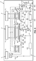
- the Figure 1 illustrates a thermal device 2 according to the invention, hereinafter device 2.
- the device 2 is coupled to an installation 4 for heating and / or production of domestic hot water and / or air conditioning to meet the corresponding needs of an infrastructure 6 to which the device 2 and the installation 4 are associated.
- the installation 4 comprises for example a heating means 4 1 , a domestic hot water production means 4 2 and an air conditioning / cooling means 4 3 .
- the device 2 comprises a first, a second and a third heat pump, hereinafter pumps PAC1, PAC2, PAC3 respectively.
- the device 2 comprises a first capture circuit CC1 and a second capture circuit CC2.
- the PAC1 and PAC2 pumps are thermally connectable to the first capture circuit CC1 and / or the second capture circuit CC2.
- the PAC3 is thermally connectable to the first DC sensing circuit 1.
- thermal connectable is meant that each pump PAC1 to PAC3 is adapted to be switched between a connected configuration in which it exchanges heat with the capture circuit considered, and a disconnected configuration in which it does not exchange heat with the capture circuit considered.
- the connection or the disconnection of a pump to a capture circuit is obtained by switching on or off the pump in question and / or by the implementation of switching means described below. .
- the pumps PAC1 to PAC3 each comprise a condenser Ci and an evaporator Ei thermally connected to each other.
- the evaporator is intended to capture calories from equipment external to PACi to which it is thermally connected, and return these calories via the condenser to a second external equipment.
- the two capture circuits CC1 and CC2 are designed to allow heat transfer between the equipment connected to these circuits.
- the two capture circuits CC1 and CC2 are in particular thermally connectable to the heat pump PAC 1, and more precisely to its evaporator.
- the first capture circuit CC1 is thermally connectable to the second and third pumps PAC2, PAC3. More particularly, the first capture circuit CC1 is connectable to the condenser C2 of the second pump PAC2 and to the evaporator E3 of the third pump PAC3.
- the second capture circuit CC2 is thermally connectable to the second pump PAC2, and more particularly to its evaporator E2.
- the first capture circuit CC1 forms a hot loop of the device 2, that is to say a loop provided for the implementation of the heating function and possibly the production of domestic hot water.
- the first circuit CC1 comprises a supplementary heat source SCA (hereinafter source SCA) and one or more buried sensors CE1. These different elements are connected to each other via a set of ducts defining a closed loop connecting (or able to connect) in series the PAC1 to PAC3 pumps, the source SCA, the buried sensors CE1 and the circulation means. Within this circuit CC1 circulates a heat transfer fluid FC1. This heat transfer fluid is for example glycol water.
- the first circuit CC1 further comprises switching means MA and circulation means MC.
- the first capture circuit CC1 comprises temperature probes for measuring the temperature T1 at the input of the source SCA, the temperature T2 at the output of the source SCA, the temperature Te at the input of the buried sensors CE1 and the temperature Ts in output of buried sensors.
- the SCA source is intended to provide calories to heat transfer fluid FC1.
- This source SCA is for example in the form of a set of solar panels or aerosol sensors. These panels or sensors are for example arranged on a roof of the infrastructure 6, or on pergolas located near the infrastructure 6, or even on the ground.
- the buried CE1 sensors are buried in the ground around or under the infrastructure 6. They are thermally connected to the ground and allow thermal exchanges between the fluid coolant FC1 and the soil itself. These buried sensors CE1 are for example known invoice sensors.
- the switching means MA are adapted to selectively connect and thermally disconnect the pumps PAC1, PAC2, PAC3 as well as the source SCA of the capture circuit CC1.
- the switching means MA comprise, for each of these elements, a main branch Bpr thermally connecting the heat transfer fluid to the equipment in question when it passes through this main branch and a parallel branch Bpa to the branch. main arrangement for thermally isolating the heat transfer fluid of the equipment considered during its passage through this parallel branch.
- the switching means comprise MS selection mechanisms configured to select the branch by which the heat transfer fluid FC1 must pass for each pair of branches Bpr / Bpa, that is to say for each selectively connectable equipment circuit capture CC1.
- These selection mechanisms comprise for example one or more valves controlled at the opening and closing for the selection of one or the other main or parallel branches. The control of these valves is described in more detail below.
- the selection mechanism MS associated with the source SCA is configured for, when the corresponding parallel branch Bpa is activated, to force the passage of the heat transfer fluid FC1 through the source SCA at a regular frequency for a short period of time. This makes it possible to obtain a measurement of the temperature T2 when the source SCA is disconnected. This period of time is for example of the order of one minute, the frequency in question being, for example, once an hour.
- the parallel and main branches and the selection mechanisms associated with the PAC1 to PAC3 pumps are optional, the thermal connection and disconnection of the PAC1 to PAC3 pumps to the CC1 capture circuit being possible by turning on and off the PAC1 pumps to PAC3 themselves.
- the circulation means MC are adapted to circulate the heat transfer fluid FC1 in the sensing circuit CC1 in a flow direction S1.
- the circulation means MC comprise at least one circulation pump (not shown).
- the circulation means MC are adapted to circulate the coolant between the connected elements, and more particularly between the pump PAC1, the source SCA and the buried sensor CE1, according to a first sequence according to which, when these elements are connected to the capture circuit CC1, once out of the pump PAC1, the heat transfer fluid FC1 passes first in the source SCA and then in the buried sensor CE1.
- the circulation means MC are adapted to circulate the coolant between the pump PAC1, the source SCA and the buried sensor CE1, according to a second sequence according to which, when these elements are connected to the capture circuit CC1, once out of the pump PAC1, the heat transfer fluid FC1 passes first into the buried sensor CE1 and then into the source SCA.
- the circulation means MC comprise first, second and third circulation branches B1, B2, B3 respectively (hereinafter branches B1, B2, B3), these branches each fluidly connecting two points of the sensing circuit CC1 between them .
- the circulation means MC comprise first, second and third activation means M1, M2, M3 for the activation and deactivation of the first, second, and third branches B1, B2, B3, respectively.
- the first activation means M1 are arranged between the output of the third pump PAC3 and the selection mechanism MS associated with the source SCA.
- the first branch B1 has an input end BE1 to the capture circuit CC1 connected to the first activation means M1, and an output end BS1 connected to the input of the buried sensor CE1.
- the second activation means M2 are arranged downstream of the output of the buried sensor CE1.
- the second branch B2 has an input end BE2 connected to the second activation means M2 and an output end BS2 connected to the circuit CC1 between the first activation means M1 and the selection mechanism MS associated with the source SCA.
- the third activation means M3 are arranged between the output of the source SCA and the input of the buried sensor CE1.
- the third branch B3 comprises an input end BE3 connected to the third activation means M3 and an output end BS3 connected between the second activation means M2 and the selection mechanism MS associated with the heat pump PAC 1.
- the activation means M1, M2, M3 comprise one or more valves controlled at the opening or closing for the activation and deactivation of the corresponding circulation branch Bi.
- the first and the second sequences are implemented by selective activation of the branches B1, B2, B3 via the activation means M1, M2, M3.
- the activation means when the activation means activate the associated branch, they also prevent the circulation of the heat transfer fluid downstream via the branch of the capture circuit CC1 to which they are connected and which is not the circulation branch Bi corresponding activatable.
- they include for example a check valve.
- the second capture circuit CC2 comprises a heat exchange means ECH, one or more buried sensors CE2 called cold sensors and second switching means MA2. These elements are connected to each other via a set of conduits defining a second closed loop, in this case a cold loop, within which a second heat transfer fluid FC2 circulates.
- This fluid is for example also glycol water.
- the heat transfer fluid FC2 flows in the sensing circuit CC2 in a direction through the pump PAC1, the pump PAC2, the exchange means ECH and the cold sensors CE2 in this order.
- the heat exchange medium ECH is in thermal connection with the means of air conditioning / refresh April 3 and is suitable for removing calories this way on April 3.
- the heat exchange means ECH directly exchanges calories with the means 4 3 . It is for example in the form of a mixing valve between the coolant FC2 and a fluid from the means 4 3 . Alternatively, the heat exchange means ECH indirectly exchanges calories with the average 4 3 . It is then for example in the form of a heat exchanger for the exchange of heat between the coolant FC2 and the medium 4 3 .
- the cold sensor (s) CE2 is distinct from the buried sensor CE1.
- the cold sensor CE2 is also buried.
- the cold sensor CE2 is, for example, invoice identical to that of the sensor CE1, and is buried at a similar depth.
- the cold sensor CE2 is sufficiently far away from the buried sensor CE2 to be influenced at the more than negligibly by the possible calorie releases of the buried sensor CE1 in the soil.
- the second switching means MA2 are adapted to selectively connect and thermally disconnect the pump PAC1 and the pump PAC2 of the second circuit CC2.
- the second switching means MA2 comprise main and parallel branches and selection mechanisms MS for each of the pumps PAC1 and PAC2.
- switching means MA2 are optional.
- the connection and the disconnection of the pumps PAC1 and PAC2 to the second capture circuit CC2 can be achieved by only switching on and off the pumps PAC1 and PAC2 themselves.
- their presence as well as the presence of the switching means MA are advantageous under certain conditions, in particular when it is desired to thermally connect the pump PAC1 to one of the circuits CC1, CC2 but not to the other.
- the choice of the operating mode is conditioned by the need or not for heating the infrastructure 6.
- the operating mode is for example selected manually, or automatically. In the latter case, the operating mode is for example selected automatically according to the date, the outside temperature or the heating demand of the building.
- the winter mode of operation is for example implemented from October to May, the summer mode of operation being implemented in other months of the year.
- the device 2 is used to produce domestic hot water and possibly to cool part of the infrastructure 6, such as a room containing computer servers, via the air conditioning / cooling means. 4 3 .
- the operating mode of the device 2 is selected, that is to say either the winter operating mode, which gives rise to a winter operation step H, or the summer operating mode , which gives rise to a summer operation step E.
- step H the device 2 is used at least for heating the infrastructure 6 via the pump PAC1, and 4 1 Heating means, as indicated above.
- the pump PAC2 is stopped, the switching means MA and MA2 disconnecting the second pump PAC2 of the capture circuit CC1, respectively the second capture circuit CC2.
- the pump PAC1 when used to heat the infrastructure 6, the pump PAC1 is not maintained switched on continuously, but is switched off with a frequency dependent on the heating requirements of the infrastructure 6.
- step H the configuration of the second capture circuit CC2 for the conditioning of the infrastructure 6 is determined and the determined configuration is applied. Three configurations are possible.
- the fluid FC2 is circulated, the infrastructure having needs for air conditioning or strong heating needs.
- the pump PAC1 is connected to the second capture circuit CC2 via its start-up and / or via the switching means MA2.
- the pump PAC1 takes heat from the second heat transfer fluid.
- This configuration is selected when the temperature T3 at the output of the cold sensors CE2 or at the input of the exchange medium ECH is greater than a target temperature Tc referred to at the input of the exchange means.
- This configuration is also selected when the heating requirements of the means 4 3 are greater than a predetermined threshold, regardless of the comparison between the temperatures T3 and Tc.
- the heat transfer fluid passes from the output of the cold sensors CE2 to the input of the exchange means ECH without going through the heat pump PAC1, which is then thermally disconnected from the second circuit CC2.
- This configuration is selected when the temperature T3 is lower than the temperature Tc and the heating requirements are below the predetermined threshold.
- this CLIM H stage occurs at regular frequency, or on command in response to an event, such as a predetermined change in temperature T3.
- the third heat pump PAC3 is connected to the capture circuit CC1, via its start-up and / or via the switching means MA.
- This step is for example triggered automatically at regular frequency, for example daily, and is interrupted after a predetermined period of time. In practice, this step is implemented for the production of a quantity of domestic hot water sufficient for the needs of the infrastructure 6.
- the PAC3 pump is disconnected from the capture circuit CC1 at the end of this step.
- step H it is determined whether or not the connection of the source SCA to the pickup circuit CC1 is to be operated, and, if necessary, this connection is made. This determination is a function of the comparison between the inlet T1 and T2 output temperatures of the fluid FC1 with respect to the source SCA.
- the switching means MA disconnect the source SCA when the temperature T2 is lower than the temperature T1.
- the parallel branch Bpa parallel to the source SCA is then used by the coolant FC1.
- the switching means MA connect the source SCA when the temperature T2 is greater than the temperature T1.
- This step is repeated at regular frequency, or on command, for example in response to a change in temperature T1 and / or temperature T2.
- the SCA source when the SCA source is thermally connected to the CC1 circuit and the PAC1 and PAC3 pumps are thermally disconnected, the SCA source thermally recharges the ground around the CE1 sensor.
- step H the configuration of the circulation means MC is determined and this configuration is implemented. In particular, it is determined whether the branches B1, B2 and / or B3 must be activated.
- This determination is made according to the input T1 and output T2 of the source SCA, and the input temperature Te and Ts output of the buried sensor CE1.
- the source SCA is disconnected from the capture circuit.
- the branches B1 to B3 are all three deactivated.
- the heat transfer fluid FC1 then takes the continuous line path of the Figure 3 , except for the fact that it borrows the parallel branch Bpa of the source SCA (and possibly the parallel branch Bpa of the PAC3 when the step ECS H does not take place in parallel).
- the branches B1 to B3 are all deactivated.
- the heat transfer fluid FC1 takes the continuous line path on the Figure 3 (possibly modified at the level of the PAC3 pump when this one is deactivated).
- the first sequence is implemented by the circulation means at least temporarily (that is to say when the pump PAC1 is thermally connected to the circuit CC1): once out of the pump PAC1, the heat transfer fluid FC1 goes through the SCA source and then through the buried sensor CE1.
- the temperature Ts is lower than the temperature Te.
- the branches B1 to B3 are then all activated (and the branches of the sensing circuit to which the activation means M1 to M3 are connected other than the circulation branches B1 to B3 are closed by the activation means M1 to M3).
- the fluid FC1 borrows the branch B1 and is thus routed to the input of the buried sensor CE1.
- the fluid borrows the branch B2, which routes it up between the activation means M1 and the selection mechanism MS of the source SCA. This sends the fluid FC1 through the source SCA.
- the coolant FC1 borrows the branch B3, which routes it between the activation means M2 and the input of the pump PAC1.
- the second sequence is implemented by the circulation means at least temporarily (that is to say when the pump PAC1 is thermally connected to the circuit CC1).
- the pump PAC1 is not necessarily thermally connected continuously to the sensing circuit CC1.
- the heat transfer fluid FC1 carries out a heat transfer between the source SCA and the buried sensor CE1. This has the effect of thermally recharging the soil in which the buried sensor CE1 is located.
- the pump PAC1 is connected to the circuit CC1, the corresponding sequence is implemented.
- This CIRCUL H stage takes place for example at regular frequency, or on command, for example in response to a variation of the temperature Te or the temperature Ts.
- the first sequence is implemented by the circulation means MC.
- the device 2 is not used to heat the infrastructure 6.
- the PAC1 pump is kept stopped.
- step E the configuration of the second capture circuit CC2 is determined and the corresponding configuration is implemented.
- the coolant FC2 is not circulated in the circuit CC2. This configuration is selected when infrastructure 6 is not needed in air conditioning. Conversely, in the second and third configurations, the fluid FC2 is circulated and the infrastructure has a need for air conditioning.
- the evaporator E2 of the pump PAC2 is thermally connected to the second sensing circuit CC2.
- This configuration is selected when the infrastructure 6 has cooling needs and the temperature T3 is higher than the target temperature Tc. In this configuration, the evaporator E2 takes heat from the coolant FC2 and lowers the temperature.
- the pump PAC2 is thermally disconnected from the circuit CC2, the heat transfer fluid FC2 passing from the output of the cold sensors CE2 to the input of the exchange means ECH without passing through the pump PAC2.
- This configuration is selected when the temperature T3 is lower than the temperature Tc.
- the heat transfer fluid FC2 does not need to see its temperature lowered by the pump PAC2.
- This step is for example carried out at regular frequency, or on command, for example in response to a variation of temperature T3.
- the pump PAC3 is thermally connected to the collector circuit CC1, via its start and / or via the switching means MA. This connection is maintained throughout the duration of this ECS stage E , after which the PAC3 pump is again disconnected from the CC1 sensing circuit.
- This step is for example triggered automatically at regular frequency, for example daily, and is interrupted after a predetermined period of time.
- the configuration of the capture circuit CC1 is determined as a function of the temperatures T1 and T2, of the configuration of the second capture circuit CC2, and whether or not the step is carried out in parallel with the ECS step E. Note that this configuration does not imply the connection and disconnection of the PAC3 pump CC1 capture circuit, that is to say that the implementation of the configurations during this step does not go through the connection or the Disconnection of the PAC3 pump from the CC1 circuit.
- the circulation means MC do not circulate the heat transfer fluid FC1 within the circuit CC1.
- This configuration is selected when the temperature T2 is lower than the temperature T1, the ECS step E does not take place in parallel and the second capture circuit is in the first configuration (fluid FC2 not flowing).
- the heat transfer fluid FC1 is circulated and the source SCA is connected to the circuit CC1 via the switching means.
- branches B1 to B3 are disabled.
- This configuration is selected when the temperature T2 is greater than the temperature T1.
- This configuration is implemented whether the ECS step E runs in parallel or not and regardless of the configuration of the second capture circuit CC2.
- the heat transfer fluid thermally recharges the soil due to the heat input of the source SCA. Due to this thermal recharge of the ground, the temperature Ts is lower than the temperature Te.
- the heat transfer fluid FC1 flows and the source SCA is disconnected from the circuit CC1 via the switching means.
- This configuration is selected when the temperature T2 is lower than the temperature T1 and the step ECS E runs in parallel.
- This configuration is implemented regardless of the configuration of the second capture circuit CC2 and regardless of the temperatures Te and Ts.
- the CE1 buried sensors supply heat to the PAC3 pump for the production of domestic hot water.
- step H the substeps of step E can take place in any order and in parallel or not.
- the invention has many advantages. Indeed, the circulation of the heat transfer fluid according to the first sequence makes it possible to improve the thermal efficiency of the device 2. In fact, under certain conditions, in particular when the ground around the buried sensors CE1 is sufficiently hot, the passage of the fluid in the SCA source and then in the CE1 buried sensors maximizes thermal energy recovery. Thus, in the event that the second sequence was implemented under these conditions, the heat recovery via the buried sensors CE1 would be such that the source SCA would heat only slightly or not at all the coolant.
- the ability of reversing the relative circulation between the buried sensor CE1 and the source SCA supplied by the circulation means MC makes it possible to adapt the device 2 to the conditions external to the device 2.
- the first sequence is preferred under the above conditions, the second sequence being preferred under the conditions generally occurring in the mid-winter / summer season.
- the presence of the second capture circuit CC2 dedicated to air conditioning and also coupled to the PAC1 pump ensures optimal and via a single device the needs for air conditioning and heating and possibly domestic hot water of the Infrastructure 6.
- the coupling of the two circuits via the heat pump PAC1 makes it possible to reduce the dimensioning of the equipment of the device 2, in particular heat pumps and buried sensors. This is advantageous in that these sensors are expensive in themselves, complex to install and require a minimum of space available on the ground and in the basement.
- this dimensioning is further optimized by the connection of the condenser of the second heat pump to the collector circuit CC1, which makes it possible to increase the heat transfer in the desired direction between the two circuits CC1 and CC2.
- the selective connection of the SCA source makes it possible to limit any losses that can be generated by the passage of the coolant through the SCA source, particularly in the case of low outside temperature.
- the switching means MA and MA2 of the two circuits also contribute to the effectiveness of the device by allowing the short circuit of the equipment of the device 2 when the passage of the heat transfer fluid within them is not necessary or detrimental to the thermal efficiency of the device.
- the device 2 comprises more than three PAC1 to PAC3 pumps in series or in parallel.
- the condenser of the pump PAC2 is connected to a cooling tower rather than to the heat capture circuit CC1.
- the condenser C1 of the pump PAC1 is thermally connectable to the circuit CC1, for example via a selection mechanism MS and main branches Bpr and parallel Bpa.
- the condenser of the pump PAC1 is thermally connected to the circuit CC1 and the evaporator E1 of the pump PAC1 is connected to the circuit CC2.
- These connections are implemented parallel or alternatively to the connection of the pump PAC2 to the second circuit CC2.
- the device 2 does not include PAC2 pump.
- the device may comprise a plurality of sensors CE1 and CE2 forming a group of sensors CE1 and a group of sensors CE2.
- the above description then applies to sensor groups CE1 and CE2 rather than isolated sensors.
- the flow direction of the second heat transfer fluid within the second circuit CC2 is the opposite direction of that illustrated in the Figures.
- the fluid FC2 passes into the cold sensor CE2, then into the exchange means ECH, then possibly into the second pump PAC2 and possibly in the first PAC1 pump.
- the preferred meaning is the flow direction illustrated in the Figures.
- the second pump PAC2 is connectable to the first capture circuit CC1 via two-point connected conduits arranged in series on a branch of the circuit CC1 located between the output of the PAC3 and the source SCA .
- connection of these conduits to the capture circuit can be achieved at another point of the circuit CC1.
- these conduits are connected to two points of the circuit CC1 arranged in series between the activation means M3 and the input of the buried sensor CE1 (arrows A and B on the Figure 4 ).
- these points are connected for one near the buried sensor output and for the input near the buried sensor input.
- the source selection mechanism MS SCA comprises a diversion valve configured to pass a portion of the coolant FC1 through the parallel branch Bpa of the source SCA while the main branch Bpr of the source SCA is busy. This makes it possible to ensure that the heat transfer fluid flow FC1 in the main branch Bpr does not exceed a limit value whose exceeding could damage the branch Bpr and possibly the source SCA.
- the switching elements provided for the connection and the disconnection of the PAC1 to PAC3 pumps of the circuits CC1 and CC2 are optional.
- the connection and the disconnection of the pumps PAC1 to PAC3 of these circuits are then implemented by the start-up or shutdown of the pumps PAC1 to PAC3 themselves.
- the temperature T3 is alternately the temperature at the input of the exchange means ECH.
Landscapes
- Engineering & Computer Science (AREA)
- Chemical & Material Sciences (AREA)
- Combustion & Propulsion (AREA)
- Mechanical Engineering (AREA)
- General Engineering & Computer Science (AREA)
- Life Sciences & Earth Sciences (AREA)
- Physics & Mathematics (AREA)
- Thermal Sciences (AREA)
- Sustainable Energy (AREA)
- Sustainable Development (AREA)
- Air Conditioning Control Device (AREA)
- Other Air-Conditioning Systems (AREA)
Claims (12)
- Thermische Vorrichtung für eine Anlage (4) zur Heizung und/oder zur Erzeugung von warmem Brauchwasser und/oder zur Klimatisierung, wobei die thermische Vorrichtung umfasst:- eine Wärmepumpe (PAC1), und- einen Wärmegewinnungskreis (CC1), der mit der Wärmepumpe (PAC1) thermisch verbindbar ist und aufweist:wobei die Umwälzmittel (MC) dafür ausgelegt sind, das Wärmeträgerfluid innerhalb des Wärmegewinnungskreises gemäß einer Folge umzuwälzen, gemäß welcher, nachdem das Wärmeträgerfluid aus der Wärmepumpe (PAC1) ausgetreten ist, das Wärmeträgerfluid (FC1) zuerst die Zusatzwärmequelle (SCA) und danach den erdverlegten Sensor (CE1) durchströmt,- eine Zusatzwärmequelle (SCA),- wenigstens einen erdverlegten Sensor (CE1),- ein Wärmeträgerfluid (FC1),- Weichenmittel (MA) für die thermische Verbindung und die thermische Trennung der Zusatzwärmequelle (SCA) mit bzw. von dem Gewinnungskreis (CC1), und- Umwälzmittel (MC), die dafür ausgelegt sind, das Wärmeträgerfluid innerhalb des Wärmegewinnungskreises umzuwälzen,
wobei die thermische Vorrichtung außerdem einen zweiten Gewinnungskreis (CC2) umfasst, der mit der Wärmepumpe (PAC1) verbindbar ist, wobei der zweite Gewinnungskreis (CC2) umfasst- wenigstens einen erdverlegten Sensor (CE2), kalter Sensor genannt, wobei der kalte Sensor von dem erdverlegten Sensor (CE1) des Wärmegewinnungskreises (CC1) verschieden ist,- ein Wärmeaustauschmittel (ECH), das dafür ausgelegt ist, eine Einrichtung zu kühlen, und- ein zweites Wärmeträgerfluid (FC2), das dafür ausgelegt ist, innerhalb des zweiten Gewinnungskreises (CC2) zu zirkulieren,dadurch gekennzeichnet, dass die Vorrichtung außerdem eine zweite Wärmepumpe (PAC2) umfasst, die einen Kondensator (C2) und einen Verdampfer (E2) umfasst, wobei der Verdampfer (E2) der zweiten Wärmepumpe (PAC2) mit dem zweiten Gewinnungskreis (CC2) thermisch verbindbar ist, wobei der Kondensator (C2) der zweiten Wärmepumpe mit dem Wärmegewinnungskreis (CC1) thermisch verbindbar ist. - Vorrichtung nach Anspruch 1, dadurch gekennzeichnet, dass die Umwälzmittel (MC) außerdem dafür ausgelegt sind, das Wärmeträgerfluid innerhalb des Wärmegewinnungskreises (CC1) gemäß einer zweiten Folge umzuwälzen, gemäß welcher, nachdem das Wärmeträgerfluid aus der Wärmepumpe (PAC1) ausgetreten ist, das Wärmeträgerfluid (FC1) zuerst den erdverlegten Sensor (CE1) und danach die Zusatzwärmequelle (SCA) durchströmt.
- Vorrichtung nach Anspruch 2, dadurch gekennzeichnet, dass die Umwälzmittel (MC) einen ersten, einen zweiten und einen dritten Zirkulationsstrang (B1, B2, B3) umfassen, die selektiv aktivierbar sind, wobei der erste Zirkulationsstrang (B1) einen ersten Punkt (BE1) des Gewinnungskreises (CC1), der zwischen einem Ausgang der Wärmepumpe und einem Eingang der Zusatzwärmequelle angeordnet ist, mit einem Eingang des erdverlegten Sensors (CE1) thermisch verbindet, wobei der zweite Zirkulationsstrang (B2) einen Ausgang des erdverlegten Sensors (CE1) mit einem zweiten Punkt (BS2) des Gewinnungskreises (CC1), der zwischen dem ersten Punkt und dem Eingang der Zusatzwärmequelle (SCA) angeordnet ist, thermisch verbindet, wobei der dritte Strang (B3) einen dritten Punkt (BE3) des Gewinnungskreises (CC1), der zwischen dem Ausgang der Zusatzwärmequelle (SCA) und dem Eingang des erdverlegten Sensors (CE1) angeordnet ist, mit einem vierten Punkt (BS3) des Wärmegewinnungskreises (CC1), der zwischen dem Ausgang des erdverlegten Sensors (CE1) und dem Eingang der Wärmepumpe (PAC1) angeordnet ist, thermisch verbindet.
- Vorrichtung nach einem der vorhergehenden Ansprüche, dadurch gekennzeichnet, dass die Wärmepumpe (PAC1) und/oder die zweite Wärmepumpe (PAC2) in Reaktion auf die Erkennung einer Temperatur (T3) des zweiten Wärmeträgerfluids (FC2) am Ausgang des wenigstens einen kalten Sensors (CE2) oder am Eingang des Wärmeaustauschmittels (ECH), die niedriger als eine Zieltemperatur (Tc) am Eingang des Wärmeaustauschmittels (ECH) ist, von dem zweiten Gewinnungskreis (CC2) thermisch getrennt werden.
- Vorrichtung nach einem der vorhergehenden Ansprüche, dadurch gekennzeichnet, dass sie außerdem eine dritte Wärmepumpe (PAC3) umfasst, die für die Erzeugung von warmem Brauchwasser bestimmt ist, wobei die dritte Wärmepumpe (PAC3) einen Verdampfer (E3) umfasst, der mit dem Wärmegewinnungskreis (CC1) thermisch verbindbar ist.
- Verfahren zur Verwendung einer thermischen Vorrichtung nach einem der vorhergehenden Ansprüche für eine Anlage zur Heizung und/oder zur Erzeugung von warmem Brauchwasser und/oder zur Klimatisierung, welcher die thermische Vorrichtung zugeordnet ist, wobei das Verfahren einen Betriebsschritt (CIRCULH) umfasst, in dessen Verlauf die Zusatzwärmequelle (SCA) und die Wärmepumpe (PAC1) mit dem Wärmegewinnungskreis (CC1) thermisch verbunden sind und das Wärmeträgerfluid (FC1) innerhalb des Wärmegewinnungskreises gemäß einer Folge umgewälzt wird, gemäß welcher, nachdem das Wärmeträgerfluid aus der Wärmepumpe ausgetreten ist, das Wärmeträgerfluid (FC1) zuerst die Zusatzwärmequelle (SCA) und danach den erdverlegten Sensor (CE1) durchströmt, wobei das Verfahren außerdem umfasst:- einen Schritt des Winterbetriebs (H), in dessen Verlauf die Anlage zum Heizen verwendet wird, wobei die Wärmepumpe (PAC1) wenigstens zeitweilig mit dem Wärmegewinnungskreis (CC1) thermisch verbunden wird und Wärme aus dem Wärmegewinnungskreis (CC1) entnimmt, um sie an ein Heizmittel (41) der Anlage abzugeben, und- einen Schritt des Sommerbetriebs (E), in dessen Verlauf die Anlage nicht verwendet wird, um dem Heizmittel Wärme zu liefern,wobei im Verlaufe des Schrittes des Winterbetriebs (H) die Wärmepumpe auch mit dem zweiten Wärmegewinnungskreis thermisch verbunden wird und in Reaktion auf die Erkennung einer Temperatur (T3) des zweiten Wärmeträgerfluids (FC2) am Ausgang des wenigstens einen kalten Sensors (CE2) oder am Eingang des Wärmeaustauschmittels (ECH) mit einem Wert, der höher als eine Zieltemperatur (Tc) am Eingang des Wärmeaustauschmittels (ECH) ist, Wärme des zweiten Wärmeträgerfluids entnimmt, dadurch gekennzeichnet, dass im Verlaufe des Schrittes des Sommerbetriebs (E) die zweite Wärmepumpe (PAC2) mit dem Wärmegewinnungskreis (CC1) thermisch verbunden wird.
- Verfahren nach Anspruch 6, wobei, unter Verwendung der Umwälzmittel (MC), die Folge durchgeführt wird, wenn die Temperatur (Te) des Wärmeträgerfluids (FC1) am Eingang des erdverlegten Sensors (CE1) niedriger als die Temperatur (Ts) des Wärmeträgerfluids am Ausgang des erdverlegten Sensors (CE1) ist und die Temperatur (T2) des Wärmeträgerfluids (FC1) am Ausgang der Zusatzwärmequelle (SCA) höher als die Temperatur (T1) des Wärmeträgerfluids (FC1) am Eingang der Zusatzwärmequelle (SCA) ist.
- Verfahren nach Anspruch 6 oder 7, wobei das Verfahren von einer thermischen Vorrichtung (2) nach Anspruch 2 durchgeführt wird, wobei, unter Verwendung der Umwälzmittel (MC), die zweite Folge durchgeführt wird, wenn die Temperatur (Te) des Wärmeträgerfluids (FC1) am Eingang des erdverlegten Sensors (CE1) höher als die Temperatur (Ts) des Wärmeträgerfluids am Ausgang des erdverlegten Sensors (CE1) ist und die Temperatur (T2) des Wärmeträgerfluids (FC1) am Ausgang der Zusatzwärmequelle (SCA) höher als die Temperatur (T1) des Wärmeträgerfluids (FC1) am Eingang der Zusatzwärmequelle (SCA) ist.
- Verfahren nach einem der Ansprüche 6 bis 8, wobei das Verfahren von einer thermischen Vorrichtung nach Anspruch 5 durchgeführt wird, wobei im Verlaufe des Schrittes des Winterbetriebs (H) die Anlage verwendet wird, um warmes Brauchwasser (ECSH) zu erzeugen, wobei die dritte Wärmepumpe (PAC3) mit dem Wärmegewinnungskreis (CC1) thermisch verbunden wird.
- Verfahren nach einem der Ansprüche 6 bis 9, wobei das Verfahren mittels einer thermischen Vorrichtung nach Anspruch 4 durchgeführt wird, wobei im Verlaufe des Schrittes des Sommerbetriebs (E) die Anlage zur Klimatisierung verwendet wird, wobei die zweite Wärmepumpe (PAC2) mit dem zweiten Wärmegewinnungskreis thermisch verbunden gehalten wird, solange die Temperatur des zweiten Wärmeträgerfluids (FC2) am Ausgang des wenigstens einen kalten Sensors (CE2) höher als die Zieltemperatur (Tc) am Eingang des Wärmeaustauschmittels (ECH) ist.
- Verfahren nach einem der Ansprüche 6 bis 10, wobei im Verlaufe des Schrittes des Sommerbetriebs (E) der Boden in der Umgebung des erdverlegten Sensors (CE1) unter Verwendung wenigstens der Zusatzwärmequelle (SCA) thermisch geladen wird.
- Verfahren nach einem der Ansprüche 6 bis 11, dadurch gekennzeichnet, dass die Zusatzwärmequelle (SCA) in Reaktion auf die Tatsache, dass die Temperatur (T2) des Wärmeträgerfluids (FC1) am Ausgang der Zusatzwärmequelle höher (T1) als die Temperatur des Wärmeträgerfluids am Eingang (T1) der Zusatzwärmequelle ist, mit dem Wärmegewinnungskreis (CC1) thermisch verbunden wird.
Priority Applications (1)
| Application Number | Priority Date | Filing Date | Title |
|---|---|---|---|
| EP14197109.3A EP3032180B1 (de) | 2014-12-10 | 2014-12-10 | Thermische Vorrichtung und Einsatzverfahren einer solchen Vorrichtung |
Applications Claiming Priority (1)
| Application Number | Priority Date | Filing Date | Title |
|---|---|---|---|
| EP14197109.3A EP3032180B1 (de) | 2014-12-10 | 2014-12-10 | Thermische Vorrichtung und Einsatzverfahren einer solchen Vorrichtung |
Publications (2)
| Publication Number | Publication Date |
|---|---|
| EP3032180A1 EP3032180A1 (de) | 2016-06-15 |
| EP3032180B1 true EP3032180B1 (de) | 2017-03-01 |
Family
ID=52146080
Family Applications (1)
| Application Number | Title | Priority Date | Filing Date |
|---|---|---|---|
| EP14197109.3A Active EP3032180B1 (de) | 2014-12-10 | 2014-12-10 | Thermische Vorrichtung und Einsatzverfahren einer solchen Vorrichtung |
Country Status (1)
| Country | Link |
|---|---|
| EP (1) | EP3032180B1 (de) |
Citations (1)
| Publication number | Priority date | Publication date | Assignee | Title |
|---|---|---|---|---|
| GB2505655A (en) * | 2012-09-05 | 2014-03-12 | Greenfield Master Ipco Ltd | Thermal energy system adapted for heating and/or cooling a building |
Family Cites Families (4)
| Publication number | Priority date | Publication date | Assignee | Title |
|---|---|---|---|---|
| FR2946126B1 (fr) | 2009-05-29 | 2013-03-15 | Electricite De France | Dispositif de chauffage utilisant une pompe a chaleur, un capteur enterre et une source d'appoint calorifique, et procede de chauffage |
| DE202009007774U1 (de) * | 2009-06-03 | 2009-10-08 | Gerngroß, Gertraud | Multifunktionale Wärmepumpe für die Kombination einer oder mehrerer Wärmequellen mittels indirekter oder direkter Verdampfung |
| GB0918438D0 (en) * | 2009-10-21 | 2009-12-09 | Dickson Stuart W | Heat transfer system |
| US8726682B1 (en) * | 2012-03-20 | 2014-05-20 | Gaylord Olson | Hybrid multi-mode heat pump system |
-
2014
- 2014-12-10 EP EP14197109.3A patent/EP3032180B1/de active Active
Patent Citations (1)
| Publication number | Priority date | Publication date | Assignee | Title |
|---|---|---|---|---|
| GB2505655A (en) * | 2012-09-05 | 2014-03-12 | Greenfield Master Ipco Ltd | Thermal energy system adapted for heating and/or cooling a building |
Also Published As
| Publication number | Publication date |
|---|---|
| EP3032180A1 (de) | 2016-06-15 |
Similar Documents
| Publication | Publication Date | Title |
|---|---|---|
| EP2232155B1 (de) | Anlage zur bereitstellung von hygienischem warmwasser für mehrfamilienhäuser | |
| WO2009071765A2 (fr) | Installation de chauffage/climatisation à pompe à chaleur, comportant un boîtier répartiteur de fluide caloporteur avec couplage à une pluralité de circuits de captage et de distribution de chaleur | |
| EP2312227B1 (de) | Mechanisch gesteuerte reversible Zweistrom-Ventilationsanlage und Brauchwarmwassererzeugung | |
| FR2922634A1 (fr) | Procede et dispositif pour l'optimisation des performances d'une installation de transfert calorifique utilisant une source d'energie calorifique de nature geothermique | |
| EP1978311A2 (de) | Von einer anderen Energiequelle unabhängiges und unabhängiges Sonnenheizungssystem | |
| WO2014044864A1 (fr) | Installation de chauffe-eau sanitaire à fonction de chauffage | |
| WO2007063119A1 (fr) | Unite solaire de production frigorifique pour installation de climatisation, unite solaire de production calorifique, dispositifs et procede de controle correspondants | |
| EP3225922B1 (de) | Kühl-, klimatisierungs- oder heizsystem | |
| FR2938900A1 (fr) | Dispositif de conditionnement d'air comportant un puit canadien et un echangeur de chaleur secondaire | |
| EP3032180B1 (de) | Thermische Vorrichtung und Einsatzverfahren einer solchen Vorrichtung | |
| EP2863130B1 (de) | Verfahren zur Regulierung einer thermischen Anlage für ein Gebäude | |
| EP3152410B1 (de) | Kraftwerk zur umwandlung von wärme in mechanische energie mit verbessertem arbeitsfluidkühlsystem | |
| FR2986860A1 (fr) | Installation thermique et procede assurant un conditionnement thermique d'un local et une production d'eau chaude sanitaire | |
| FR2487959A2 (fr) | Procede et installation d'echanges thermiques par heliogeothermie | |
| EP3581853B1 (de) | Wärmeübertragungsmodul für die erzeugung von warmwasser | |
| EP1124097B1 (de) | Heizungs- und Klimaanlage | |
| EP4028695B1 (de) | Sekundärsystem für ein niedrigtemperatur-wärmeenergieverteilungsnetz | |
| EP3910249A1 (de) | System zur erzeugung und verteilung von wärme und kälte und sein steuerungsverfahren | |
| FR2946126A1 (fr) | Dispositif de chauffage utilisant une pompe a chaleur, un capteur enterre et une source d'appoint calorifique, et procede de chauffage | |
| FR2639009A1 (fr) | Dispositif de chauffage pour vehicule automobile comportant un generateur de chaleur | |
| EP3816523B1 (de) | Heizungsanlage für einen raum mit einer frostschutzvorrichtung im falle einer fehlenden stromversorgung | |
| FR2913757A1 (fr) | Dispositif de couplage d'un systeme de chauffage a liquide caloporteur a un dispositif de refroidissement | |
| EP4545864A1 (de) | Verfahren und vorrichtung zur verwaltung von wärmeenergie für eine wohnanlage | |
| EP2241828B1 (de) | verbesserte Warmwasseranlage mit variablem Volumen | |
| FR2533300A1 (fr) | Dispositif pour la gestion optimale d'energie delivree par un ensemble de capteurs solaires |
Legal Events
| Date | Code | Title | Description |
|---|---|---|---|
| PUAI | Public reference made under article 153(3) epc to a published international application that has entered the european phase |
Free format text: ORIGINAL CODE: 0009012 |
|
| 17P | Request for examination filed |
Effective date: 20150730 |
|
| AK | Designated contracting states |
Kind code of ref document: A1 Designated state(s): AL AT BE BG CH CY CZ DE DK EE ES FI FR GB GR HR HU IE IS IT LI LT LU LV MC MK MT NL NO PL PT RO RS SE SI SK SM TR |
|
| AX | Request for extension of the european patent |
Extension state: BA ME |
|
| RIC1 | Information provided on ipc code assigned before grant |
Ipc: F24F 5/00 20060101ALI20160901BHEP Ipc: F24D 19/10 20060101ALI20160901BHEP Ipc: F25B 30/02 20060101ALN20160901BHEP Ipc: F24D 17/02 20060101ALI20160901BHEP Ipc: F24D 3/18 20060101AFI20160901BHEP |
|
| GRAP | Despatch of communication of intention to grant a patent |
Free format text: ORIGINAL CODE: EPIDOSNIGR1 |
|
| INTG | Intention to grant announced |
Effective date: 20161010 |
|
| STAA | Information on the status of an ep patent application or granted ep patent |
Free format text: STATUS: GRANT OF PATENT IS INTENDED |
|
| GRAS | Grant fee paid |
Free format text: ORIGINAL CODE: EPIDOSNIGR3 |
|
| GRAA | (expected) grant |
Free format text: ORIGINAL CODE: 0009210 |
|
| STAA | Information on the status of an ep patent application or granted ep patent |
Free format text: STATUS: THE PATENT HAS BEEN GRANTED |
|
| AK | Designated contracting states |
Kind code of ref document: B1 Designated state(s): AL AT BE BG CH CY CZ DE DK EE ES FI FR GB GR HR HU IE IS IT LI LT LU LV MC MK MT NL NO PL PT RO RS SE SI SK SM TR |
|
| REG | Reference to a national code |
Ref country code: GB Ref legal event code: FG4D Free format text: NOT ENGLISH |
|
| REG | Reference to a national code |
Ref country code: CH Ref legal event code: EP Ref country code: AT Ref legal event code: REF Ref document number: 871843 Country of ref document: AT Kind code of ref document: T Effective date: 20170315 |
|
| REG | Reference to a national code |
Ref country code: IE Ref legal event code: FG4D Free format text: LANGUAGE OF EP DOCUMENT: FRENCH |
|
| REG | Reference to a national code |
Ref country code: DE Ref legal event code: R096 Ref document number: 602014007093 Country of ref document: DE |
|
| REG | Reference to a national code |
Ref country code: NL Ref legal event code: MP Effective date: 20170301 |
|
| REG | Reference to a national code |
Ref country code: LT Ref legal event code: MG4D |
|
| REG | Reference to a national code |
Ref country code: AT Ref legal event code: MK05 Ref document number: 871843 Country of ref document: AT Kind code of ref document: T Effective date: 20170301 |
|
| PG25 | Lapsed in a contracting state [announced via postgrant information from national office to epo] |
Ref country code: GR Free format text: LAPSE BECAUSE OF FAILURE TO SUBMIT A TRANSLATION OF THE DESCRIPTION OR TO PAY THE FEE WITHIN THE PRESCRIBED TIME-LIMIT Effective date: 20170602 Ref country code: NO Free format text: LAPSE BECAUSE OF FAILURE TO SUBMIT A TRANSLATION OF THE DESCRIPTION OR TO PAY THE FEE WITHIN THE PRESCRIBED TIME-LIMIT Effective date: 20170601 Ref country code: HR Free format text: LAPSE BECAUSE OF FAILURE TO SUBMIT A TRANSLATION OF THE DESCRIPTION OR TO PAY THE FEE WITHIN THE PRESCRIBED TIME-LIMIT Effective date: 20170301 Ref country code: LT Free format text: LAPSE BECAUSE OF FAILURE TO SUBMIT A TRANSLATION OF THE DESCRIPTION OR TO PAY THE FEE WITHIN THE PRESCRIBED TIME-LIMIT Effective date: 20170301 Ref country code: FI Free format text: LAPSE BECAUSE OF FAILURE TO SUBMIT A TRANSLATION OF THE DESCRIPTION OR TO PAY THE FEE WITHIN THE PRESCRIBED TIME-LIMIT Effective date: 20170301 |
|
| PG25 | Lapsed in a contracting state [announced via postgrant information from national office to epo] |
Ref country code: ES Free format text: LAPSE BECAUSE OF FAILURE TO SUBMIT A TRANSLATION OF THE DESCRIPTION OR TO PAY THE FEE WITHIN THE PRESCRIBED TIME-LIMIT Effective date: 20170301 Ref country code: RS Free format text: LAPSE BECAUSE OF FAILURE TO SUBMIT A TRANSLATION OF THE DESCRIPTION OR TO PAY THE FEE WITHIN THE PRESCRIBED TIME-LIMIT Effective date: 20170301 Ref country code: LV Free format text: LAPSE BECAUSE OF FAILURE TO SUBMIT A TRANSLATION OF THE DESCRIPTION OR TO PAY THE FEE WITHIN THE PRESCRIBED TIME-LIMIT Effective date: 20170301 Ref country code: SE Free format text: LAPSE BECAUSE OF FAILURE TO SUBMIT A TRANSLATION OF THE DESCRIPTION OR TO PAY THE FEE WITHIN THE PRESCRIBED TIME-LIMIT Effective date: 20170301 Ref country code: AT Free format text: LAPSE BECAUSE OF FAILURE TO SUBMIT A TRANSLATION OF THE DESCRIPTION OR TO PAY THE FEE WITHIN THE PRESCRIBED TIME-LIMIT Effective date: 20170301 Ref country code: BG Free format text: LAPSE BECAUSE OF FAILURE TO SUBMIT A TRANSLATION OF THE DESCRIPTION OR TO PAY THE FEE WITHIN THE PRESCRIBED TIME-LIMIT Effective date: 20170601 |
|
| PG25 | Lapsed in a contracting state [announced via postgrant information from national office to epo] |
Ref country code: NL Free format text: LAPSE BECAUSE OF FAILURE TO SUBMIT A TRANSLATION OF THE DESCRIPTION OR TO PAY THE FEE WITHIN THE PRESCRIBED TIME-LIMIT Effective date: 20170301 |
|
| PG25 | Lapsed in a contracting state [announced via postgrant information from national office to epo] |
Ref country code: EE Free format text: LAPSE BECAUSE OF FAILURE TO SUBMIT A TRANSLATION OF THE DESCRIPTION OR TO PAY THE FEE WITHIN THE PRESCRIBED TIME-LIMIT Effective date: 20170301 Ref country code: RO Free format text: LAPSE BECAUSE OF FAILURE TO SUBMIT A TRANSLATION OF THE DESCRIPTION OR TO PAY THE FEE WITHIN THE PRESCRIBED TIME-LIMIT Effective date: 20170301 Ref country code: CZ Free format text: LAPSE BECAUSE OF FAILURE TO SUBMIT A TRANSLATION OF THE DESCRIPTION OR TO PAY THE FEE WITHIN THE PRESCRIBED TIME-LIMIT Effective date: 20170301 Ref country code: SK Free format text: LAPSE BECAUSE OF FAILURE TO SUBMIT A TRANSLATION OF THE DESCRIPTION OR TO PAY THE FEE WITHIN THE PRESCRIBED TIME-LIMIT Effective date: 20170301 |
|
| PG25 | Lapsed in a contracting state [announced via postgrant information from national office to epo] |
Ref country code: PL Free format text: LAPSE BECAUSE OF FAILURE TO SUBMIT A TRANSLATION OF THE DESCRIPTION OR TO PAY THE FEE WITHIN THE PRESCRIBED TIME-LIMIT Effective date: 20170301 Ref country code: PT Free format text: LAPSE BECAUSE OF FAILURE TO SUBMIT A TRANSLATION OF THE DESCRIPTION OR TO PAY THE FEE WITHIN THE PRESCRIBED TIME-LIMIT Effective date: 20170703 Ref country code: SM Free format text: LAPSE BECAUSE OF FAILURE TO SUBMIT A TRANSLATION OF THE DESCRIPTION OR TO PAY THE FEE WITHIN THE PRESCRIBED TIME-LIMIT Effective date: 20170301 Ref country code: IS Free format text: LAPSE BECAUSE OF FAILURE TO SUBMIT A TRANSLATION OF THE DESCRIPTION OR TO PAY THE FEE WITHIN THE PRESCRIBED TIME-LIMIT Effective date: 20170701 |
|
| REG | Reference to a national code |
Ref country code: DE Ref legal event code: R097 Ref document number: 602014007093 Country of ref document: DE |
|
| REG | Reference to a national code |
Ref country code: FR Ref legal event code: PLFP Year of fee payment: 4 |
|
| PLBE | No opposition filed within time limit |
Free format text: ORIGINAL CODE: 0009261 |
|
| STAA | Information on the status of an ep patent application or granted ep patent |
Free format text: STATUS: NO OPPOSITION FILED WITHIN TIME LIMIT |
|
| PG25 | Lapsed in a contracting state [announced via postgrant information from national office to epo] |
Ref country code: DK Free format text: LAPSE BECAUSE OF FAILURE TO SUBMIT A TRANSLATION OF THE DESCRIPTION OR TO PAY THE FEE WITHIN THE PRESCRIBED TIME-LIMIT Effective date: 20170301 |
|
| 26N | No opposition filed |
Effective date: 20171204 |
|
| PG25 | Lapsed in a contracting state [announced via postgrant information from national office to epo] |
Ref country code: SI Free format text: LAPSE BECAUSE OF FAILURE TO SUBMIT A TRANSLATION OF THE DESCRIPTION OR TO PAY THE FEE WITHIN THE PRESCRIBED TIME-LIMIT Effective date: 20170301 |
|
| REG | Reference to a national code |
Ref country code: CH Ref legal event code: PL |
|
| REG | Reference to a national code |
Ref country code: IE Ref legal event code: MM4A |
|
| PG25 | Lapsed in a contracting state [announced via postgrant information from national office to epo] |
Ref country code: LU Free format text: LAPSE BECAUSE OF NON-PAYMENT OF DUE FEES Effective date: 20171210 Ref country code: MT Free format text: LAPSE BECAUSE OF FAILURE TO SUBMIT A TRANSLATION OF THE DESCRIPTION OR TO PAY THE FEE WITHIN THE PRESCRIBED TIME-LIMIT Effective date: 20170301 |
|
| REG | Reference to a national code |
Ref country code: BE Ref legal event code: MM Effective date: 20171231 |
|
| PG25 | Lapsed in a contracting state [announced via postgrant information from national office to epo] |
Ref country code: IE Free format text: LAPSE BECAUSE OF NON-PAYMENT OF DUE FEES Effective date: 20171210 |
|
| PG25 | Lapsed in a contracting state [announced via postgrant information from national office to epo] |
Ref country code: BE Free format text: LAPSE BECAUSE OF NON-PAYMENT OF DUE FEES Effective date: 20171231 Ref country code: LI Free format text: LAPSE BECAUSE OF NON-PAYMENT OF DUE FEES Effective date: 20171231 Ref country code: CH Free format text: LAPSE BECAUSE OF NON-PAYMENT OF DUE FEES Effective date: 20171231 |
|
| PG25 | Lapsed in a contracting state [announced via postgrant information from national office to epo] |
Ref country code: MC Free format text: LAPSE BECAUSE OF FAILURE TO SUBMIT A TRANSLATION OF THE DESCRIPTION OR TO PAY THE FEE WITHIN THE PRESCRIBED TIME-LIMIT Effective date: 20170301 Ref country code: HU Free format text: LAPSE BECAUSE OF FAILURE TO SUBMIT A TRANSLATION OF THE DESCRIPTION OR TO PAY THE FEE WITHIN THE PRESCRIBED TIME-LIMIT; INVALID AB INITIO Effective date: 20141210 |
|
| PG25 | Lapsed in a contracting state [announced via postgrant information from national office to epo] |
Ref country code: CY Free format text: LAPSE BECAUSE OF FAILURE TO SUBMIT A TRANSLATION OF THE DESCRIPTION OR TO PAY THE FEE WITHIN THE PRESCRIBED TIME-LIMIT Effective date: 20170301 |
|
| PG25 | Lapsed in a contracting state [announced via postgrant information from national office to epo] |
Ref country code: MK Free format text: LAPSE BECAUSE OF FAILURE TO SUBMIT A TRANSLATION OF THE DESCRIPTION OR TO PAY THE FEE WITHIN THE PRESCRIBED TIME-LIMIT Effective date: 20170301 |
|
| PG25 | Lapsed in a contracting state [announced via postgrant information from national office to epo] |
Ref country code: TR Free format text: LAPSE BECAUSE OF FAILURE TO SUBMIT A TRANSLATION OF THE DESCRIPTION OR TO PAY THE FEE WITHIN THE PRESCRIBED TIME-LIMIT Effective date: 20170301 |
|
| PG25 | Lapsed in a contracting state [announced via postgrant information from national office to epo] |
Ref country code: AL Free format text: LAPSE BECAUSE OF FAILURE TO SUBMIT A TRANSLATION OF THE DESCRIPTION OR TO PAY THE FEE WITHIN THE PRESCRIBED TIME-LIMIT Effective date: 20170301 |
|
| PGFP | Annual fee paid to national office [announced via postgrant information from national office to epo] |
Ref country code: IT Payment date: 20201214 Year of fee payment: 7 |
|
| PG25 | Lapsed in a contracting state [announced via postgrant information from national office to epo] |
Ref country code: IT Free format text: LAPSE BECAUSE OF NON-PAYMENT OF DUE FEES Effective date: 20211210 |
|
| P01 | Opt-out of the competence of the unified patent court (upc) registered |
Effective date: 20231024 |
|
| PGFP | Annual fee paid to national office [announced via postgrant information from national office to epo] |
Ref country code: GB Payment date: 20251229 Year of fee payment: 12 |
|
| PGFP | Annual fee paid to national office [announced via postgrant information from national office to epo] |
Ref country code: FR Payment date: 20251121 Year of fee payment: 12 |
|
| PGFP | Annual fee paid to national office [announced via postgrant information from national office to epo] |
Ref country code: DE Payment date: 20251231 Year of fee payment: 12 |