EP2241864A2 - Dispositif de mesure du débit d'un fluid avec un dispositif de liaison pour le capteur - Google Patents
Dispositif de mesure du débit d'un fluid avec un dispositif de liaison pour le capteur Download PDFInfo
- Publication number
- EP2241864A2 EP2241864A2 EP10003843A EP10003843A EP2241864A2 EP 2241864 A2 EP2241864 A2 EP 2241864A2 EP 10003843 A EP10003843 A EP 10003843A EP 10003843 A EP10003843 A EP 10003843A EP 2241864 A2 EP2241864 A2 EP 2241864A2
- Authority
- EP
- European Patent Office
- Prior art keywords
- differential pressure
- pressure sensor
- channels
- sensor
- coupling
- Prior art date
- Legal status (The legal status is an assumption and is not a legal conclusion. Google has not performed a legal analysis and makes no representation as to the accuracy of the status listed.)
- Granted
Links
Images

Classifications
-
- G—PHYSICS
- G01—MEASURING; TESTING
- G01F—MEASURING VOLUME, VOLUME FLOW, MASS FLOW OR LIQUID LEVEL; METERING BY VOLUME
- G01F1/00—Measuring the volume flow or mass flow of fluid or fluent solid material wherein the fluid passes through a meter in a continuous flow
- G01F1/05—Measuring the volume flow or mass flow of fluid or fluent solid material wherein the fluid passes through a meter in a continuous flow by using mechanical effects
- G01F1/34—Measuring the volume flow or mass flow of fluid or fluent solid material wherein the fluid passes through a meter in a continuous flow by using mechanical effects by measuring pressure or differential pressure
- G01F1/36—Measuring the volume flow or mass flow of fluid or fluent solid material wherein the fluid passes through a meter in a continuous flow by using mechanical effects by measuring pressure or differential pressure the pressure or differential pressure being created by the use of flow constriction
- G01F1/40—Details of construction of the flow constriction devices
- G01F1/44—Venturi tubes
-
- G—PHYSICS
- G01—MEASURING; TESTING
- G01F—MEASURING VOLUME, VOLUME FLOW, MASS FLOW OR LIQUID LEVEL; METERING BY VOLUME
- G01F1/00—Measuring the volume flow or mass flow of fluid or fluent solid material wherein the fluid passes through a meter in a continuous flow
- G01F1/05—Measuring the volume flow or mass flow of fluid or fluent solid material wherein the fluid passes through a meter in a continuous flow by using mechanical effects
- G01F1/34—Measuring the volume flow or mass flow of fluid or fluent solid material wherein the fluid passes through a meter in a continuous flow by using mechanical effects by measuring pressure or differential pressure
- G01F1/36—Measuring the volume flow or mass flow of fluid or fluent solid material wherein the fluid passes through a meter in a continuous flow by using mechanical effects by measuring pressure or differential pressure the pressure or differential pressure being created by the use of flow constriction
-
- G—PHYSICS
- G01—MEASURING; TESTING
- G01F—MEASURING VOLUME, VOLUME FLOW, MASS FLOW OR LIQUID LEVEL; METERING BY VOLUME
- G01F15/00—Details of, or accessories for, apparatus of groups G01F1/00 - G01F13/00 insofar as such details or appliances are not adapted to particular types of such apparatus
- G01F15/18—Supports or connecting means for meters
Definitions
- the invention relates to a device for measuring the volume or mass flow of a medium according to the differential pressure method, with a pressure-bearing housing part with a measuring section, open into the at least two differential pressure channels, wherein a differential pressure sensor can be brought into operative connection with the differential pressure channels.
- the flow measurement according to the differential pressure method is the most widely used method, among other things, since no moving components have to be introduced into the stream for measuring the volume or mass flow of a medium to be measured.
- the differential pressure method is based on the measurement of at least two absolute pressures that prevail in the fluid system along a measurement path.
- a device In the measuring section, a device is usually provided which changes the flow cross section in sections. As a result, a dependent of the volume or mass flow pressure difference is generated, which is used as a measured variable.
- a device of the type mentioned is, for example, in the DE 37 10 968 C2 disclosed.
- the device there has a measuring section with at least one exchangeable measuring orifice and measuring connections on both sides of the measuring orifice, to which pressure sensors can be connected.
- the measuring connections are designed as couplings which can be coupled to the connections of the pressure sensors under the operating pressure, and the pressure sensors are galvanically connected to a processor-controlled evaluation device.
- pressure sensors simple pressure sensors are used.
- differential pressure sensors devices of the type mentioned with so-called differential pressure sensors are known.
- the known from the prior art devices for measuring the volume or mass flow, the differential pressure sensors use however, have the disadvantage that they are regularly designed for permanent installation, so that the known differential pressure sensors are always mounted.
- differential pressure sensors are relatively sensitive and have a low stability in many machines due to the pressure conditions and mechanical loads.
- the invention has the object to improve a device of the type mentioned in that it overcomes the disadvantages of the prior art and allows a montage and procedurally simple to perform measurement of the volume or mass flow of a medium.
- a device for measuring the volumetric or mass flow of a medium, for example a fluid, such as oil or the like, which operates according to the differential pressure method, has a pressure-bearing housing part with a measuring path, along which several effective pressures are measured. For tapping the effective pressures at least two differential pressure channels are provided, which open into the measuring section.
- a differential pressure differential is provided with the Wirkdruckkanälen in pressure transmission connection differential pressure sensor. With the help of the differential pressure sensor, a pressure difference along the measuring section can be determined in a conventional manner.
- the differential pressure channels can be connected via a common coupling to a counter-coupling of the differential pressure sensor and that means for positionally or positionally reliable connection of the differential pressure channels with the differential pressure sensor are provided.
- the differential pressure sensor is thus removable from the pressure-bearing housing part in a simple manner and connectable in the same way. This will be the advantage ensures that the differential pressure sensor must be mounted on the measuring section only when a measurement is actually made. At the same time it is avoided that for attaching the device for measuring the medium-carrying part whose volume or mass flow of medium to be measured, must be opened. It is also avoided by the invention that several individual sensors must be mounted. By forming means for positionally secure connection of the differential pressure channels with the pressure sensor prevents the sensors are mounted in the wrong position and thereby a false measurement result is generated.
- the pressure-bearing housing may be an integral part of a machine or device.
- the coupling has a connecting piece connected to the housing part and comprising the differential pressure channels for connection of the differential pressure sensor.
- the differential pressure sensor can be mounted very easily on the pressure-bearing housing part.
- connection can be particularly easy to achieve assembly technology, even if the counter-coupling has a measuring channels of the differential pressure sensor comprehensive mating connector, so that a simple and fast connection and detachment of the differential pressure sensor is reached.
- means for coupling the differential pressure channels to the differential pressure sensor are provided under operating pressure.
- the differential pressure sensor to the pressure-bearing housing part is connected or removable, so there is no loss of media or oil during the connection and removal of the differential pressure sensor.
- the pressure sensors can therefore be brought into the zero balancing circuit as well as into the measuring position under any given operating conditions at any reference pressure. A plant standstill with domes or decrease of the measuring device does not occur.
- check valves are provided as means for coupling the differential pressure channels, which are preferably mechanically unlockable. With the help of such check valves, the respective differential pressure line can be particularly easily shut off when no differential pressure sensor is mounted.
- the one or more non-return valves are also mechanically unlockable, an unlocking of the check valve and thus an opening of the differential pressure channels can be achieved by mounting the flow sensor. In this way it is particularly easy to achieve an operative connection between the differential pressure channels and the differential pressure sensor.
- the opening fitting of the check valves is arranged as an integral part, which further simplifies handling when connecting and removing the differential pressure sensor.
- the differential pressure sensor has sealing nipples via which the differential pressure sensor can be operatively connected to the differential pressure channels in a position fastened to the housing part.
- sealing nipple With the help of the sealing nipple, a secure sealing of the connection between differential pressure sensor and differential pressure channels can be achieved.
- the sealing nipples are preferably designed as hollow pins, which protrude into the fitting of the pressure-bearing housing part in the mounting position of the differential pressure sensor on the measuring section. This makes it possible to achieve a particularly good sealing of the connection.
- the hollow pins are furthermore designed to unlock the mechanically unlockable non-return valves provided according to the development described above, a particularly simple installation of the differential pressure sensor can be realized.
- the preferably designed as O-rings seals are arranged such that when connecting the differential pressure sensor, the sealing nipple with the housing-side seals in operative position before the check valves reach the open position. This proves to be a particularly effective and structurally advantageous measure to be able to make the coupling of the differential pressure channels with the differential pressure sensor under operating pressure. Both when coupling and when taking the measuring device no plant standstill occurs. A medium or oil loss during installation and removal of the differential pressure sensor thus no longer occurs.
- the connector has a threaded connector and the differential pressure sensor to a union nut, by means of which the differential pressure sensor is attached to the connector.
- a quick coupling allows a simple and pressure-tight attachment of the differential pressure sensor.
- the means for the correct position connecting the differential pressure channels with the differential pressure sensor have at least one bore and a pin connectable thereto. This ensures that the differential pressure sensor is mounted in the correct orientation.
- Preferred means for this purpose are at least one Codierbohrung and a Kodierzapfen, wherein the Codierbohrung can be provided in the pressure-bearing housing part or in the differential pressure sensor and the coding pin in the respective other component.
- a particularly preferred embodiment provides for the arrangement of the coding bore in the pressure-bearing housing part and that of the coding pin in the differential pressure sensor.
- a screw cap is preferably provided, which terminates the connection region to the differential pressure sensor. This can prevent mechanical damage and contamination of the connection area.
- the pressure-bearing housing part preferably has a nozzle insert, wherein the one pressure-pressure channel opens into the measuring section in the region of the nozzle insert.
- the nozzle insert is preferably designed as Venturi nozzle insert.
- the nozzle insert may be integrally provided in the housing part or as an exchangeable nozzle insert.
- the differential pressure sensor has at least two sensor chambers connectable to the at least two differential pressure channels. In this way, the differential pressure along the measuring section can be determined particularly easily.
- Another independent subject relates to a machine having a device according to the invention described above. Such a machine allows easy monitoring of the media-carrying systems during operation with high reliability.
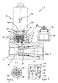
- Fig. 1 shows a device 2 according to the invention for measuring the volume or mass flow of a medium according to the differential pressure method.
- the device is designed as a flow measuring device with a Q-diagnostic measuring coupling and can be designed for different volume flows, for example 2 to 40 liters per minute, 5 to 100 liters per minute or 30 to 600 liters per minute.
- the device 2 according to the invention can be readily adapted to pressure ranges up to 650 bar.
- the illustrated device 2 is designed for liquid operating media, such as hydraulic oils, HFC fluids or water. Of course, the device can be used with advantage for gaseous media.
- the device 2 has a pressure-bearing housing part 4 through which the medium to be measured flows.
- a differential pressure channel 6, 8 are provided, via which a differential pressure sensor 10 can be acted upon by the differential pressure prevailing at the respective location.
- the differential pressure sensor 10 is designed to be removable from the pressure-bearing housing part 4.
- a connecting piece 12 is provided on the pressure-bearing housing part 4, which has a threaded connector 14 for fastening the differential pressure sensor 10.
- the differential pressure sensor 10 in turn has a union nut 16 by means of which a screw connection of the differential pressure sensor 10 with the threaded connector 14 of the connecting piece 12 of the housing part 4 is possible and a quick coupling is provided.
- the two differential pressure channels 6, 8 define a measuring section 18 along which a measurement of two effective pressures is made.
- One differential pressure channel 6 opens into a Venturi nozzle insert 20 provided in the pressure-bearing housing part 4, whereby a difference in the prevailing effective pressures which prevail in the differential pressure channels 6, 8 is achieved.
- the differential pressure is dependent on the volume or mass flow of the medium flowing through.
- differential pressure channels 6, 8 mechanically check valves 22, 24 are provided which lock the differential pressure sensor 10, the differential pressure channels 6, 8 and prevent leakage of the medium through the differential pressure channels 6, 8.
- the mechanically unlockable check valves 22, 24 are unlocked by the assembly of the differential pressure sensor 10.
- O-rings 36 are provided, which seal the hollow pin 30, 32 against the differential pressure channels 6, 8 and the union nut 16 against the connector 12.
- the seals 36 are arranged such that when connecting the differential pressure sensor 10, the sealing nipple 30, 32 come into operative position with the seals 36 before the check valves 22, 24 reach the open position.
- a fastened to the pressure-bearing housing part 4 screw cap 34 is used to seal the connector 12 with disassembled differential pressure sensor 10, see Fig. 4 ,
- the differential pressure sensor 10 is usually disassembled and stored separately.
- the screw cap 34 is, as in Fig. 4 shown screwed onto the threaded connector 14 of the connecting piece 12 of the pressure-bearing housing part 4.
- the differential pressure channels 6, 8 are closed by the check valves 22, 24.
- the screw cap 34 is unscrewed and the differential pressure sensor 10 is placed on the connector 12 and mounted by means of the union nut 16 on the threaded connector 14 of the connector 12.
- the hollow pins 30, 32 are inserted into the differential pressure channels 6, 8 and open with their end faces the check valves 22, 24, so that an operative connection between the measuring section 18 and sensor chambers 38 of the differential pressure sensor 10 is made.
- a sealing of the between the pressure differential channels 6, 8 and measuring channels 46, 48 of the differential pressure sensor 10 is achieved via the formed as O-rings seals 36. Afterwards the flow rate can be measured. In this case, the fluid is prevented from escaping during the assembly of the differential pressure sensor 10.
- Fig. 2 shows a section along the section line AA through the connection region of pressure-bearing housing part 4 and differential pressure sensor 10 according to Fig. 1 ,
- a coding pin 28 is provided in the illustrated cross-section, by means of which and the associated coding bore 26 is accomplished that the differential pressure sensor 10 can be mounted only in the correct position on the pressure-bearing housing part 4.
- the hollow pins 30, 32 and the coding pin 28 are not distributed symmetrically over the cross section for this purpose.
- Fig. 3 shows a further section through the device 2 in the connection area along the section line BB according to Fig. 2 ,
- the Kodierzapfen 28 in position, depth and diameter adapted Codierbohrung 26 is provided so that the Kodierzapfen 28 protrudes exactly into the Codierbohrung 26.
- the coding pin 28 is fixed in the differential pressure sensor 10.
- Fig. 4 shows the device 2 according to the invention with disassembled differential pressure sensor 10.
- the screw cap 34 is screwed onto the threaded connector 14.
- the check valves 22, 24 are closed.
- the screw cap 34 has a punch 42 with a seal.
- a locking ring is called, which allows the rotatability of the union nut 16 relative to the connecting piece 12 of the differential pressure sensor 10 when connecting and disconnecting.
- the screw cap 34 is also held by means of a locking ring 50 on the punch 42 rotatable.
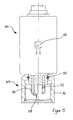
- Fig. 5 shows the differential pressure sensor 10 of the device 2 according to the invention separately.
- An opening fitting 44 formed from the already described components union nut 16, hollow pin 30, 32, Kodierzapfen 28, is shown in section.
- the hollow pins 30, 32 are fluidly connected to the sensor chambers 38.
- the sensor chambers 38 take on each hollow pin 30, 32 to a pressure and a pressure difference is determined.
- a usual differential pressure is between 0 and 2 bar, depending on the respective volume or mass flow and the specific configuration of the Venturidüsendones 20th
- the differential pressure can, for example, be transmitted electrically to an evaluation unit and / or displayed on the differential pressure sensor via suitable display means.
Landscapes
- Physics & Mathematics (AREA)
- Fluid Mechanics (AREA)
- General Physics & Mathematics (AREA)
- Measuring Fluid Pressure (AREA)
- Measuring Volume Flow (AREA)
Applications Claiming Priority (1)
| Application Number | Priority Date | Filing Date | Title |
|---|---|---|---|
| DE102009017335A DE102009017335A1 (de) | 2009-04-14 | 2009-04-14 | Vorrichtung zur Messung des Volumen- oder Massestromes eines Mediums, Maschine mit entsprechender Vorrichtung |
Publications (3)
| Publication Number | Publication Date |
|---|---|
| EP2241864A2 true EP2241864A2 (fr) | 2010-10-20 |
| EP2241864A3 EP2241864A3 (fr) | 2012-01-11 |
| EP2241864B1 EP2241864B1 (fr) | 2018-08-08 |
Family
ID=42404900
Family Applications (1)
| Application Number | Title | Priority Date | Filing Date |
|---|---|---|---|
| EP10003843.9A Active EP2241864B1 (fr) | 2009-04-14 | 2010-04-10 | Dispositif de mesure du débit d'un fluid avec un dispositif de liaison pour le capteur |
Country Status (3)
| Country | Link |
|---|---|
| EP (1) | EP2241864B1 (fr) |
| DE (1) | DE102009017335A1 (fr) |
| ES (1) | ES2693435T3 (fr) |
Cited By (1)
| Publication number | Priority date | Publication date | Assignee | Title |
|---|---|---|---|---|
| CN105547573A (zh) * | 2016-02-19 | 2016-05-04 | 中煤科工集团重庆研究院有限公司 | 一种v型管式倾斜微压计及其测量方法 |
Families Citing this family (2)
| Publication number | Priority date | Publication date | Assignee | Title |
|---|---|---|---|---|
| DE102012106037B4 (de) | 2012-07-05 | 2017-11-23 | Stephan Wille | Kupplungssystem mit elektronisch gesteuerter Trennung |
| DE202015100728U1 (de) | 2015-02-16 | 2015-03-06 | Parker Hannifin Manufacturing Germany GmbH & Co. KG | Messkupplung mit einem RFID-Transponder |
Citations (2)
| Publication number | Priority date | Publication date | Assignee | Title |
|---|---|---|---|---|
| DE3710968C2 (fr) | 1987-04-01 | 1989-12-07 | Hydrotechnik Gmbh, 6250 Limburg, De | |
| DE69629388T2 (de) | 1995-12-20 | 2004-07-01 | The Dow Chemical Co., Midland | Verfahren zur installierung eines druckdifferenzumsetzers |
Family Cites Families (9)
| Publication number | Priority date | Publication date | Assignee | Title |
|---|---|---|---|---|
| US1858399A (en) * | 1928-05-21 | 1932-05-17 | Jones Barton | Flow-meter construction |
| US3431935A (en) * | 1965-10-23 | 1969-03-11 | Foxboro Co | Apparatus for use in the measurement of fluid flow |
| US4582089A (en) * | 1984-10-31 | 1986-04-15 | General Screw Products Company | Valve manifold having a removable flange |
| DD239665A1 (de) * | 1985-07-23 | 1986-10-01 | Dessau Gas & Elektrogeraete | Ueberdruckfuehlersicherung, insbesondere fuer elektronische durchflussmesser |
| ATE55467T1 (de) * | 1986-02-17 | 1990-08-15 | Hydrotechnik Gmbh | Fluidisches system mit messvorrichtung. |
| JPH0255123U (fr) * | 1988-10-12 | 1990-04-20 | ||
| US6324917B1 (en) * | 1999-03-11 | 2001-12-04 | Mark Products, Inc. | Combination air pipe connector and flow measurement device |
| US6311568B1 (en) * | 1999-09-13 | 2001-11-06 | Rosemount, Inc. | Process flow device with improved pressure measurement feature |
| DE20305230U1 (de) * | 2003-04-01 | 2003-06-18 | FESTO AG & Co., 73734 Esslingen | Durchfluss-Messvorrichtung |
-
2009
- 2009-04-14 DE DE102009017335A patent/DE102009017335A1/de not_active Withdrawn
-
2010
- 2010-04-10 EP EP10003843.9A patent/EP2241864B1/fr active Active
- 2010-04-10 ES ES10003843.9T patent/ES2693435T3/es active Active
Patent Citations (2)
| Publication number | Priority date | Publication date | Assignee | Title |
|---|---|---|---|---|
| DE3710968C2 (fr) | 1987-04-01 | 1989-12-07 | Hydrotechnik Gmbh, 6250 Limburg, De | |
| DE69629388T2 (de) | 1995-12-20 | 2004-07-01 | The Dow Chemical Co., Midland | Verfahren zur installierung eines druckdifferenzumsetzers |
Cited By (1)
| Publication number | Priority date | Publication date | Assignee | Title |
|---|---|---|---|---|
| CN105547573A (zh) * | 2016-02-19 | 2016-05-04 | 中煤科工集团重庆研究院有限公司 | 一种v型管式倾斜微压计及其测量方法 |
Also Published As
| Publication number | Publication date |
|---|---|
| ES2693435T3 (es) | 2018-12-11 |
| DE102009017335A1 (de) | 2010-10-28 |
| EP2241864A3 (fr) | 2012-01-11 |
| EP2241864B1 (fr) | 2018-08-08 |
Similar Documents
| Publication | Publication Date | Title |
|---|---|---|
| DE3638604A1 (de) | Fluidisches system mit volumenstrommesseinrichtung | |
| EP2241864B1 (fr) | Dispositif de mesure du débit d'un fluid avec un dispositif de liaison pour le capteur | |
| EP1068467A1 (fr) | Dispositif pour le montage ulterieur d'un debitmetre dans une canalisation | |
| EP3309528A1 (fr) | Transmetteur de pression de tubulure | |
| DE102010032575A1 (de) | Steckscheibe für den Einbau zwischen zwei Flanschen einer Flanschverbindung | |
| DE102014005783A1 (de) | Verbindungsvorrichtung zum Herstellen eines Anschlusses zwischen einem Messgerät/Ventilblock und einer Pipeline | |
| DE102012018731A1 (de) | Sicherheitsabsperrvorrichtung und Verfahren zu seiner Herstellung | |
| DE19704656A1 (de) | Einrichtung zur Lenkung, Steuerung, Regelung, Messung und Überwachung von Flüssigkeitsströmen und Wasseraufbereitungsanlage | |
| DE202016101941U1 (de) | Druckmindereranordnung | |
| DE4007279C2 (de) | Anschlußvorrichtung für Einstutzen-Gaszähler | |
| DE10227373B4 (de) | Rohrförmige Staudrucksonde | |
| DE962485C (de) | Absperrvorrichtung, bei der Einlaufleitung und Auslaufleitung konzentrisch oder unmittelbar nebeneinander angeordnet sind | |
| EP4191111B1 (fr) | Couplage de guidage de média et guidage de média | |
| DE2712953A1 (de) | Kombinierte gasabsperr- und gasdruckpruefvorrichtung | |
| DE19829969A1 (de) | Vorrichtung zum Überprüfen der Dichtigkeit von Muffenverbindungsbereichen an Abwasserrohren bzw. -kanälen | |
| DE102020122652A1 (de) | Druckgasfilter mit Durchgangsöffnung im Gehäusekopf | |
| DE10044144B4 (de) | Anschlussvorrichtung zum Verbinden einer Fluidleitung mit einer zweiten Anschlussvorrichtung | |
| DE2929480A1 (de) | Armatur mit mehrfachfunktion | |
| DE102024001424B3 (de) | Leitungskupplung | |
| EP2561258B1 (fr) | Soupape d'arrêt avec dispositif de blocage et purge | |
| DE102019001742A1 (de) | Vorrichtung zum Messen und/oder Regeln und Verfahren | |
| DE202018103691U1 (de) | Rohrfedermanometer aus Vollkunststoff mit Überwurfmutter | |
| DE4007278A1 (de) | In einem gebaeude-anschlusskasten untergebrachte anschlussvorrichtung fuer einstutzen-gaszaehler | |
| DE102016005040A1 (de) | Strömungsmessgerät für ein Kühlmedium | |
| EP2192353B1 (fr) | Dispositif de détermination de la différence de pression sur une installation d'eau chaude |
Legal Events
| Date | Code | Title | Description |
|---|---|---|---|
| PUAI | Public reference made under article 153(3) epc to a published international application that has entered the european phase |
Free format text: ORIGINAL CODE: 0009012 |
|
| AK | Designated contracting states |
Kind code of ref document: A2 Designated state(s): AT BE BG CH CY CZ DE DK EE ES FI FR GB GR HR HU IE IS IT LI LT LU LV MC MK MT NL NO PL PT RO SE SI SK SM TR |
|
| AX | Request for extension of the european patent |
Extension state: AL BA ME RS |
|
| PUAL | Search report despatched |
Free format text: ORIGINAL CODE: 0009013 |
|
| AK | Designated contracting states |
Kind code of ref document: A3 Designated state(s): AT BE BG CH CY CZ DE DK EE ES FI FR GB GR HR HU IE IS IT LI LT LU LV MC MK MT NL NO PL PT RO SE SI SK SM TR |
|
| AX | Request for extension of the european patent |
Extension state: AL BA ME RS |
|
| RIC1 | Information provided on ipc code assigned before grant |
Ipc: G01F 15/18 20060101ALI20111205BHEP Ipc: G01F 1/44 20060101AFI20111205BHEP Ipc: G01F 1/36 20060101ALI20111205BHEP |
|
| 17P | Request for examination filed |
Effective date: 20120224 |
|
| 17Q | First examination report despatched |
Effective date: 20141030 |
|
| GRAP | Despatch of communication of intention to grant a patent |
Free format text: ORIGINAL CODE: EPIDOSNIGR1 |
|
| STAA | Information on the status of an ep patent application or granted ep patent |
Free format text: STATUS: GRANT OF PATENT IS INTENDED |
|
| INTG | Intention to grant announced |
Effective date: 20180222 |
|
| GRAS | Grant fee paid |
Free format text: ORIGINAL CODE: EPIDOSNIGR3 |
|
| GRAA | (expected) grant |
Free format text: ORIGINAL CODE: 0009210 |
|
| STAA | Information on the status of an ep patent application or granted ep patent |
Free format text: STATUS: THE PATENT HAS BEEN GRANTED |
|
| AK | Designated contracting states |
Kind code of ref document: B1 Designated state(s): AT BE BG CH CY CZ DE DK EE ES FI FR GB GR HR HU IE IS IT LI LT LU LV MC MK MT NL NO PL PT RO SE SI SK SM TR |
|
| REG | Reference to a national code |
Ref country code: GB Ref legal event code: FG4D Free format text: NOT ENGLISH |
|
| REG | Reference to a national code |
Ref country code: CH Ref legal event code: EP Ref country code: AT Ref legal event code: REF Ref document number: 1027539 Country of ref document: AT Kind code of ref document: T Effective date: 20180815 |
|
| REG | Reference to a national code |
Ref country code: IE Ref legal event code: FG4D Free format text: LANGUAGE OF EP DOCUMENT: GERMAN |
|
| REG | Reference to a national code |
Ref country code: DE Ref legal event code: R096 Ref document number: 502010015222 Country of ref document: DE |
|
| REG | Reference to a national code |
Ref country code: CH Ref legal event code: NV Representative=s name: DENNEMEYER AG, CH |
|
| REG | Reference to a national code |
Ref country code: NL Ref legal event code: FP |
|
| REG | Reference to a national code |
Ref country code: SE Ref legal event code: TRGR |
|
| REG | Reference to a national code |
Ref country code: ES Ref legal event code: FG2A Ref document number: 2693435 Country of ref document: ES Kind code of ref document: T3 Effective date: 20181211 |
|
| REG | Reference to a national code |
Ref country code: LT Ref legal event code: MG4D |
|
| REG | Reference to a national code |
Ref country code: NO Ref legal event code: T2 Effective date: 20180808 |
|
| PG25 | Lapsed in a contracting state [announced via postgrant information from national office to epo] |
Ref country code: BG Free format text: LAPSE BECAUSE OF FAILURE TO SUBMIT A TRANSLATION OF THE DESCRIPTION OR TO PAY THE FEE WITHIN THE PRESCRIBED TIME-LIMIT Effective date: 20181108 Ref country code: IS Free format text: LAPSE BECAUSE OF FAILURE TO SUBMIT A TRANSLATION OF THE DESCRIPTION OR TO PAY THE FEE WITHIN THE PRESCRIBED TIME-LIMIT Effective date: 20181208 Ref country code: PL Free format text: LAPSE BECAUSE OF FAILURE TO SUBMIT A TRANSLATION OF THE DESCRIPTION OR TO PAY THE FEE WITHIN THE PRESCRIBED TIME-LIMIT Effective date: 20180808 Ref country code: LT Free format text: LAPSE BECAUSE OF FAILURE TO SUBMIT A TRANSLATION OF THE DESCRIPTION OR TO PAY THE FEE WITHIN THE PRESCRIBED TIME-LIMIT Effective date: 20180808 Ref country code: GR Free format text: LAPSE BECAUSE OF FAILURE TO SUBMIT A TRANSLATION OF THE DESCRIPTION OR TO PAY THE FEE WITHIN THE PRESCRIBED TIME-LIMIT Effective date: 20181109 Ref country code: FI Free format text: LAPSE BECAUSE OF FAILURE TO SUBMIT A TRANSLATION OF THE DESCRIPTION OR TO PAY THE FEE WITHIN THE PRESCRIBED TIME-LIMIT Effective date: 20180808 |
|
| PG25 | Lapsed in a contracting state [announced via postgrant information from national office to epo] |
Ref country code: LV Free format text: LAPSE BECAUSE OF FAILURE TO SUBMIT A TRANSLATION OF THE DESCRIPTION OR TO PAY THE FEE WITHIN THE PRESCRIBED TIME-LIMIT Effective date: 20180808 Ref country code: HR Free format text: LAPSE BECAUSE OF FAILURE TO SUBMIT A TRANSLATION OF THE DESCRIPTION OR TO PAY THE FEE WITHIN THE PRESCRIBED TIME-LIMIT Effective date: 20180808 |
|
| PG25 | Lapsed in a contracting state [announced via postgrant information from national office to epo] |
Ref country code: EE Free format text: LAPSE BECAUSE OF FAILURE TO SUBMIT A TRANSLATION OF THE DESCRIPTION OR TO PAY THE FEE WITHIN THE PRESCRIBED TIME-LIMIT Effective date: 20180808 Ref country code: CZ Free format text: LAPSE BECAUSE OF FAILURE TO SUBMIT A TRANSLATION OF THE DESCRIPTION OR TO PAY THE FEE WITHIN THE PRESCRIBED TIME-LIMIT Effective date: 20180808 Ref country code: RO Free format text: LAPSE BECAUSE OF FAILURE TO SUBMIT A TRANSLATION OF THE DESCRIPTION OR TO PAY THE FEE WITHIN THE PRESCRIBED TIME-LIMIT Effective date: 20180808 |
|
| REG | Reference to a national code |
Ref country code: DE Ref legal event code: R097 Ref document number: 502010015222 Country of ref document: DE |
|
| PG25 | Lapsed in a contracting state [announced via postgrant information from national office to epo] |
Ref country code: DK Free format text: LAPSE BECAUSE OF FAILURE TO SUBMIT A TRANSLATION OF THE DESCRIPTION OR TO PAY THE FEE WITHIN THE PRESCRIBED TIME-LIMIT Effective date: 20180808 Ref country code: SM Free format text: LAPSE BECAUSE OF FAILURE TO SUBMIT A TRANSLATION OF THE DESCRIPTION OR TO PAY THE FEE WITHIN THE PRESCRIBED TIME-LIMIT Effective date: 20180808 Ref country code: SK Free format text: LAPSE BECAUSE OF FAILURE TO SUBMIT A TRANSLATION OF THE DESCRIPTION OR TO PAY THE FEE WITHIN THE PRESCRIBED TIME-LIMIT Effective date: 20180808 |
|
| PLBE | No opposition filed within time limit |
Free format text: ORIGINAL CODE: 0009261 |
|
| STAA | Information on the status of an ep patent application or granted ep patent |
Free format text: STATUS: NO OPPOSITION FILED WITHIN TIME LIMIT |
|
| 26N | No opposition filed |
Effective date: 20190509 |
|
| PG25 | Lapsed in a contracting state [announced via postgrant information from national office to epo] |
Ref country code: SI Free format text: LAPSE BECAUSE OF FAILURE TO SUBMIT A TRANSLATION OF THE DESCRIPTION OR TO PAY THE FEE WITHIN THE PRESCRIBED TIME-LIMIT Effective date: 20180808 |
|
| REG | Reference to a national code |
Ref country code: BE Ref legal event code: MM Effective date: 20190430 |
|
| PG25 | Lapsed in a contracting state [announced via postgrant information from national office to epo] |
Ref country code: LU Free format text: LAPSE BECAUSE OF NON-PAYMENT OF DUE FEES Effective date: 20190410 Ref country code: MC Free format text: LAPSE BECAUSE OF FAILURE TO SUBMIT A TRANSLATION OF THE DESCRIPTION OR TO PAY THE FEE WITHIN THE PRESCRIBED TIME-LIMIT Effective date: 20180808 |
|
| PG25 | Lapsed in a contracting state [announced via postgrant information from national office to epo] |
Ref country code: BE Free format text: LAPSE BECAUSE OF NON-PAYMENT OF DUE FEES Effective date: 20190430 |
|
| PG25 | Lapsed in a contracting state [announced via postgrant information from national office to epo] |
Ref country code: TR Free format text: LAPSE BECAUSE OF FAILURE TO SUBMIT A TRANSLATION OF THE DESCRIPTION OR TO PAY THE FEE WITHIN THE PRESCRIBED TIME-LIMIT Effective date: 20180808 |
|
| PG25 | Lapsed in a contracting state [announced via postgrant information from national office to epo] |
Ref country code: IE Free format text: LAPSE BECAUSE OF NON-PAYMENT OF DUE FEES Effective date: 20190410 |
|
| PG25 | Lapsed in a contracting state [announced via postgrant information from national office to epo] |
Ref country code: PT Free format text: LAPSE BECAUSE OF FAILURE TO SUBMIT A TRANSLATION OF THE DESCRIPTION OR TO PAY THE FEE WITHIN THE PRESCRIBED TIME-LIMIT Effective date: 20181208 |
|
| PG25 | Lapsed in a contracting state [announced via postgrant information from national office to epo] |
Ref country code: CY Free format text: LAPSE BECAUSE OF FAILURE TO SUBMIT A TRANSLATION OF THE DESCRIPTION OR TO PAY THE FEE WITHIN THE PRESCRIBED TIME-LIMIT Effective date: 20180808 |
|
| PG25 | Lapsed in a contracting state [announced via postgrant information from national office to epo] |
Ref country code: MT Free format text: LAPSE BECAUSE OF FAILURE TO SUBMIT A TRANSLATION OF THE DESCRIPTION OR TO PAY THE FEE WITHIN THE PRESCRIBED TIME-LIMIT Effective date: 20180808 Ref country code: HU Free format text: LAPSE BECAUSE OF FAILURE TO SUBMIT A TRANSLATION OF THE DESCRIPTION OR TO PAY THE FEE WITHIN THE PRESCRIBED TIME-LIMIT; INVALID AB INITIO Effective date: 20100410 |
|
| PG25 | Lapsed in a contracting state [announced via postgrant information from national office to epo] |
Ref country code: MK Free format text: LAPSE BECAUSE OF FAILURE TO SUBMIT A TRANSLATION OF THE DESCRIPTION OR TO PAY THE FEE WITHIN THE PRESCRIBED TIME-LIMIT Effective date: 20180808 |
|
| PGFP | Annual fee paid to national office [announced via postgrant information from national office to epo] |
Ref country code: NL Payment date: 20250418 Year of fee payment: 16 |
|
| PGFP | Annual fee paid to national office [announced via postgrant information from national office to epo] |
Ref country code: DE Payment date: 20250430 Year of fee payment: 16 |
|
| PGFP | Annual fee paid to national office [announced via postgrant information from national office to epo] |
Ref country code: GB Payment date: 20250423 Year of fee payment: 16 Ref country code: ES Payment date: 20250529 Year of fee payment: 16 |
|
| PGFP | Annual fee paid to national office [announced via postgrant information from national office to epo] |
Ref country code: NO Payment date: 20250424 Year of fee payment: 16 |
|
| PGFP | Annual fee paid to national office [announced via postgrant information from national office to epo] |
Ref country code: IT Payment date: 20250424 Year of fee payment: 16 |
|
| PGFP | Annual fee paid to national office [announced via postgrant information from national office to epo] |
Ref country code: FR Payment date: 20250424 Year of fee payment: 16 |
|
| PGFP | Annual fee paid to national office [announced via postgrant information from national office to epo] |
Ref country code: CH Payment date: 20250501 Year of fee payment: 16 |
|
| PGFP | Annual fee paid to national office [announced via postgrant information from national office to epo] |
Ref country code: AT Payment date: 20250423 Year of fee payment: 16 |
|
| PGFP | Annual fee paid to national office [announced via postgrant information from national office to epo] |
Ref country code: SE Payment date: 20250429 Year of fee payment: 16 |