EP4191111B1 - Couplage de guidage de média et guidage de média - Google Patents
Couplage de guidage de média et guidage de média Download PDFInfo
- Publication number
- EP4191111B1 EP4191111B1 EP22201816.0A EP22201816A EP4191111B1 EP 4191111 B1 EP4191111 B1 EP 4191111B1 EP 22201816 A EP22201816 A EP 22201816A EP 4191111 B1 EP4191111 B1 EP 4191111B1
- Authority
- EP
- European Patent Office
- Prior art keywords
- coupling
- media
- sensor
- coupling element
- hose
- Prior art date
- Legal status (The legal status is an assumption and is not a legal conclusion. Google has not performed a legal analysis and makes no representation as to the accuracy of the status listed.)
- Active
Links
Images
Classifications
-
- F—MECHANICAL ENGINEERING; LIGHTING; HEATING; WEAPONS; BLASTING
- F16—ENGINEERING ELEMENTS AND UNITS; GENERAL MEASURES FOR PRODUCING AND MAINTAINING EFFECTIVE FUNCTIONING OF MACHINES OR INSTALLATIONS; THERMAL INSULATION IN GENERAL
- F16L—PIPES; JOINTS OR FITTINGS FOR PIPES; SUPPORTS FOR PIPES, CABLES OR PROTECTIVE TUBING; MEANS FOR THERMAL INSULATION IN GENERAL
- F16L41/00—Branching pipes; Joining pipes to walls
- F16L41/008—Branching pipes; Joining pipes to walls for connecting a measuring instrument
-
- F—MECHANICAL ENGINEERING; LIGHTING; HEATING; WEAPONS; BLASTING
- F16—ENGINEERING ELEMENTS AND UNITS; GENERAL MEASURES FOR PRODUCING AND MAINTAINING EFFECTIVE FUNCTIONING OF MACHINES OR INSTALLATIONS; THERMAL INSULATION IN GENERAL
- F16L—PIPES; JOINTS OR FITTINGS FOR PIPES; SUPPORTS FOR PIPES, CABLES OR PROTECTIVE TUBING; MEANS FOR THERMAL INSULATION IN GENERAL
- F16L13/00—Non-disconnectable pipe joints, e.g. soldered, adhesive, or caulked joints
- F16L13/02—Welded joints
-
- F—MECHANICAL ENGINEERING; LIGHTING; HEATING; WEAPONS; BLASTING
- F16—ENGINEERING ELEMENTS AND UNITS; GENERAL MEASURES FOR PRODUCING AND MAINTAINING EFFECTIVE FUNCTIONING OF MACHINES OR INSTALLATIONS; THERMAL INSULATION IN GENERAL
- F16L—PIPES; JOINTS OR FITTINGS FOR PIPES; SUPPORTS FOR PIPES, CABLES OR PROTECTIVE TUBING; MEANS FOR THERMAL INSULATION IN GENERAL
- F16L13/00—Non-disconnectable pipe joints, e.g. soldered, adhesive, or caulked joints
- F16L13/10—Adhesive or cemented joints
-
- F—MECHANICAL ENGINEERING; LIGHTING; HEATING; WEAPONS; BLASTING
- F16—ENGINEERING ELEMENTS AND UNITS; GENERAL MEASURES FOR PRODUCING AND MAINTAINING EFFECTIVE FUNCTIONING OF MACHINES OR INSTALLATIONS; THERMAL INSULATION IN GENERAL
- F16L—PIPES; JOINTS OR FITTINGS FOR PIPES; SUPPORTS FOR PIPES, CABLES OR PROTECTIVE TUBING; MEANS FOR THERMAL INSULATION IN GENERAL
- F16L33/00—Arrangements for connecting hoses to rigid members; Rigid hose-connectors, i.e. single members engaging both hoses
- F16L33/30—Arrangements for connecting hoses to rigid members; Rigid hose-connectors, i.e. single members engaging both hoses comprising parts inside the hoses only
-
- F—MECHANICAL ENGINEERING; LIGHTING; HEATING; WEAPONS; BLASTING
- F16—ENGINEERING ELEMENTS AND UNITS; GENERAL MEASURES FOR PRODUCING AND MAINTAINING EFFECTIVE FUNCTIONING OF MACHINES OR INSTALLATIONS; THERMAL INSULATION IN GENERAL
- F16L—PIPES; JOINTS OR FITTINGS FOR PIPES; SUPPORTS FOR PIPES, CABLES OR PROTECTIVE TUBING; MEANS FOR THERMAL INSULATION IN GENERAL
- F16L37/00—Couplings of the quick-acting type
- F16L37/08—Couplings of the quick-acting type in which the connection between abutting or axially overlapping ends is maintained by locking members
- F16L37/084—Couplings of the quick-acting type in which the connection between abutting or axially overlapping ends is maintained by locking members combined with automatic locking
-
- G—PHYSICS
- G01—MEASURING; TESTING
- G01K—MEASURING TEMPERATURE; MEASURING QUANTITY OF HEAT; THERMALLY-SENSITIVE ELEMENTS NOT OTHERWISE PROVIDED FOR
- G01K1/00—Details of thermometers not specially adapted for particular types of thermometer
- G01K1/14—Supports; Fastening devices; Arrangements for mounting thermometers in particular locations
-
- G—PHYSICS
- G01—MEASURING; TESTING
- G01K—MEASURING TEMPERATURE; MEASURING QUANTITY OF HEAT; THERMALLY-SENSITIVE ELEMENTS NOT OTHERWISE PROVIDED FOR
- G01K13/00—Thermometers specially adapted for specific purposes
- G01K13/02—Thermometers specially adapted for specific purposes for measuring temperature of moving fluids or granular materials capable of flow
Definitions
- the present invention relates to a media guide coupling.
- Hoses and pipes which can also be collectively referred to as media guides, is known for transporting or guiding media, particularly fluids.
- Hoses are considered to be more flexible in terms of their material, while pipes are considered to be more rigid.
- fluids also include gases and pasty substances.
- Hose couplings of this type can also be used to connect hoses to units, which in turn have a corresponding coupling.
- Hose couplings of this type can be designed as so-called quick connectors, which can enable quick and easy connection and non-destructive release.
- Hose couplings of this type can be made of metal or plastic, in particular as injection-molded parts. This applies in a similar way to pipes. Accordingly, hose or pipe couplings of this type can also be referred to collectively as media guide couplings.
- a temperature sensor usually in the form of an NTC thermistor (negative temperature coefficient thermistor)
- NTC thermistor negative temperature coefficient thermistor
- the sensor element or the measuring transducer of the NTC thermistor extends through a through-opening of the quick coupling into the medium and thus has direct contact with the medium, which promotes the temperature transfer from the medium to the measuring transducer, ie can keep the response time of the NTC thermistor short.
- the disadvantage here is that the through-opening through the quick coupling, which is used to accommodate and feed through the measuring transducer of the NTC thermistor, must be sealed in a media-tight manner when the measuring transducer is installed. Accordingly, measures must be taken to ensure that the connection of the measuring transducer is sealed. These measures can be associated with higher costs for additional components and the risk of remaining leaks.
- Another disadvantage is that replacing the measuring transducer, for example in the event of a defect, can involve a lot of work. Due to the fact that when dismantling the removed measuring transducer, an open passage opening into the interior of the quick coupling is left behind, the medium must be removed from the system before the measuring transducer can be replaced.
- the measuring transducer of the NTC thermistor is arranged in the trough of the quick coupling and thus protrudes into the medium, surrounded in a trough-like manner by the material of the quick coupling, without coming into direct contact with the medium.
- temperature sensors can be integrated into plastic injection molded parts through invasive solutions. These solutions can consist of two different parts, where a hose coupling and the encased temperature sensors are mounted on the final part at the user's site.
- temperature sensor for example as an NTC thermistor (negative temperature coefficient thermistor), directly into an injection-molded part that forms the hose coupling.
- the housing of the temperature sensor represents a connection of the hose coupling, which is mounted within a media-carrying hose line.
- the disadvantage here is that the injection-molded parts of the hose couplings have to be individually designed for the integration of a temperature sensor. This represents additional effort. In particular, this can significantly increase the variety of parts if different temperature sensors are to be used.
- An object of the present invention is to provide a media guide coupling and in particular a quick coupling for hoses and/or pipes of the type described above, so that the disadvantages of known media guide couplings of this type are eliminated or at least reduced.
- a media guide coupling is to be created which can be adapted to different applications more easily, quickly, more cost-effectively and/or more flexibly with regard to the transmission of a sensor.
- this should be as simple, compact, cost-effective, flexible and/or intuitive as possible.
- an alternative to known media guide couplings of this type should be created.
- the present invention relates to a media guide coupling with a first coupling element with a flow opening for guiding a medium through itself, and with a first connecting element for connection to a second media-conducting device, preferably with a hose, pipe or unit, and with a second coupling element with a flow opening for guiding the medium through itself, and with a first connecting element for connection to a third media-conducting device, preferably with a hose, pipe or unit, wherein the two coupling elements are connected to one another in a media-tight manner such that their flow openings form a common flow opening of the media guide coupling, and wherein the first coupling element has a sensor receptacle and/or the second coupling element has a sensor receptacle.
- the present invention is based on the realization that it is currently complex and can lead to a corresponding variety of parts to apply sensors, such as temperature sensors in particular, to media guide couplings such as hose or pipe couplings.
- sensors such as temperature sensors in particular
- media guide couplings can be used both on Depending on the application, it must be connected to various other media-carrying devices such as hoses, pipes, units and the like on one side and on the other opposite side and designed to fit accordingly.
- different sensors must be used in terms of type, manufacturer, size and the like.
- a media guide coupling is therefore formed with and preferably consisting of two coupling elements, whereby the two coupling elements can each be designed to match one of many different media-conducting devices. Accordingly, depending on the application, i.e. depending on the media-conducting devices to be connected, two suitable coupling elements can be selected and connected to form a media guide coupling according to the invention.
- the two coupling elements can thus be manufactured separately, which significantly reduces the number of parts. This can reduce manufacturing costs.
- Providing a sensor holder for at least one of the two coupling elements can also create the possibility of using a sensor. Accordingly, the corresponding coupling element can also be designed for different sensors and connected to the other coupling element depending on the application. This can also reduce the number of parts.
- the adaptations of a media guide coupling to a new application can be reduced in that existing or already designed coupling elements only have to be recombined with each other, which can keep the effort of the adaptation low and possibly make design effort superfluous. If necessary, necessary adaptations can be limited to just one of the two coupling elements, which can also lead to a reduction in effort. In each case In this case, a two-part modularity of a media guide coupling can be made possible.
- the invention can be used for any application in which the temperature of the medium within a media guide, such as in particular within a hose or pipe system, is to be measured.
- a media guide such as in particular within a hose or pipe system
- One application that is conceivable is in particular the temperature measurement of coolants in battery-electric vehicles.
- the first coupling element has a second connecting element
- the second coupling element has a second connecting element
- the first coupling element and the second coupling element are connected to one another in a media-tight manner by means of their second connecting elements, by means of catches, clips or screws.
- a sealing element preferably an O-ring, is arranged between the two second connecting elements.
- the coupling element without a sensor holder is designed as a fiber-reinforced injection-molded part.
- This allows the corresponding properties and advantages to be applied to the media guide coupling according to the invention.
- the structure-reinforcing properties of fiber-reinforced injection-molded parts can be used in the coupling element without a sensor holder and at the same time the negative influences of fiber reinforcement in the coupling element with a sensor holder can be avoided.
- the present invention also relates to a media guide coupling with a first coupling element with a flow opening for guiding a medium through itself, and with a first connecting element for connection to a second media-guiding device, preferably with a hose, pipe or unit, with a second coupling element with a flow opening for guiding the medium through itself, and with a first connecting element for connection to a third media-guiding device, preferably with a hose, pipe or unit, and with a sensor element with a flow opening for guiding the medium through itself, wherein the first coupling element with the sensor element and the sensor element with the second coupling element are connected to one another in a media-tight manner such that their flow throughs form a common flow opening of the media guide coupling, and wherein the sensor element has a sensor receptacle.
- the previously described aspects, properties and advantages of the present invention can also be applied to a three-part media guide coupling in that the two external coupling elements can be designed and used to suit the various other media-conducting devices and can be connected to one another by means of the sensor element, which in turn can be designed or selected to suit the sensor to be used.
- This can enable the implementation of a three-part modularity.
- the first coupling element and/or the second coupling element has/have a second connecting element, wherein the sensor element has a first connecting element, preferably and a second connecting element, and wherein the first coupling element and/or the second coupling element are connected in a media-tight manner to the connecting element(s) of the sensor element.
- a sealing element preferably an O-ring, is arranged between the connecting elements (each).
- the first coupling element and/or the second coupling element is/are designed as a fiber-reinforced injection-molded part.
- the first connecting element of the first coupling element and the first connecting element of the second coupling element are designed with the same or different connection mechanisms.
- the sensor holder protrudes into the flow opening at least in sections, preferably completely, preferably perpendicular to the flow opening. This can increase the contact area between the sensor holder and thus also a sensor held by the sensor holder and thus also improve the sensory and, for example, thermal transmission between the medium and the sensor.
- the present invention further relates to a media guide with a media guide coupling as described above and with a second media-conducting device, preferably with a hose, pipe or unit.
- a media guide can thus be, for example, a hose or pipe application which has a hose or pipe as a second media-conducting device or as the actual media guide and a media guide coupling firmly and media-tightly connected thereto with, for example, a hose or pipe coupling.
- the media guide coupling according to the invention can be implemented and used in order to be able to use its properties and advantages.
- the solution is part of a modular quick connector in which the sensor and in particular the temperature measurement function is realized by integrating a, preferably cylindrical, part in the middle or at the end of the quick connector, to which a temperature sensor can be attached or directly installed.
- a solution for example, a high thermal conductivity can be achieved without having to change the existing tools.
- the production of such a, for example, temperature-sensitive quick connector can only require a small adjustment of the process.
- the solution can also enable a comparatively small volume and can be installed in any device that has a modular design.
- the solution can also be a, preferably cylindrical, part that can, for example, be mounted on any existing quick connector on one side of a male and on the other side of a female connecting element. This can enable greater flexibility in application in currently used media systems.
- This solution for example as a sensor ring, can be used for the test phase of a prototype or as a retrofittable sensor adaptation.
- the above figures are described in cylindrical coordinates with a longitudinal axis X, a radial direction R perpendicular to the longitudinal axis X and a circumferential direction U running around the longitudinal axis X.
- the longitudinal axis X, the radial direction R and the circumferential direction U can also be referred to together as spatial directions X, R, U or as cylindrical spatial directions X, R, U.
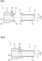
- Fig. 1 shows a longitudinal section through a media guide coupling 1 according to the invention according to a first embodiment in the separated state.
- Fig. 2 shows the representation of the Figure 1 in the connected state.
- the media guide coupling 1 is considered using the example of a hose coupling 1 in the form of a quick coupling 1.
- the hose coupling 1 has a first coupling element 10 with a flow opening 10a through which a medium such as in particular a fluid can flow along the longitudinal direction X.
- the first coupling element 10 has a first connecting element 10b and opposite it an inwardly directed second connecting element 10c.
- the first coupling element 10 also has a sensor receptacle 10d which is radially accessible from the outside and protrudes like a pin radially inwards into the flow opening 10a.
- the hose coupling 1 further comprises a second coupling element 11 with a flow opening 11a through which the fluid can flow along the longitudinal direction X.
- the second coupling element 11 comprises a first connecting element 11b and oppositely an inwardly directed second connecting element 11c.
- the two coupling elements 10, 11 are each manufactured separately as an injection-molded part, with the second coupling element 11 being designed as a fiber-reinforced injection-molded part. Both coupling elements 10, 11 can be connected in a fluid-tight manner to another media-conducting device 2, such as a hose 2, a pipe 2 or an aggregate, by means of their respective first connecting element 10b, 11b.
- Various mechanical connection mechanisms such as latches, clips or Screws can be used, especially in combination with an intermediate sealing element such as an O-ring.
- Both coupling elements 10, 11 can be connected to each other in a fixed and fluid-tight manner by means of their corresponding second connecting elements 10c, 11c, see Figure 2 so that the respective flow openings 10a, 11a of the coupling elements 10, 11 form a common flow opening 10a, 11a of the hose coupling 1.
- various mechanical connection mechanisms such as catches, clips or screws can also be used, in particular in combination with an intermediate sealing element such as an O-ring.
- the two coupling elements 10, 11 can be provided in different designs with regard to their first connecting elements 10b, 11b, so that the appropriate variant for the respective further media-carrying devices 2 can be selected from a large number of variants of first coupling elements 10 and second coupling elements 11 depending on the application.
- the first coupling element 10 can be adapted to the sensor 3 to be used with regard to its sensor holder 10d.
- the two selected coupling elements 10, 11 can then be connected to one another in a fixed and fluid-tight manner by means of their corresponding second connecting elements 10c, 11c in order to form the hose coupling 1.
- the hose coupling 1 can therefore also be referred to as a modular hose coupling 1.
- a hose coupling 1 can be created easily, flexibly and quickly, which is adapted to the respective application.
- an adaptation to the sensor 3 to be used can also be made.
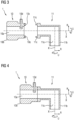
- Fig. 3 shows a longitudinal section through a media guide coupling 1 according to the invention according to a second embodiment in the separated state.
- Fig. 4 shows the representation of the Figure 3 in the connected state.
- a right-angled coupling element 11 is used as the second coupling element 11 instead of a straight coupling element 11, as is the case in the first embodiment.
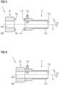
- Fig. 5 shows a longitudinal section through a media guide coupling 1 according to the invention according to a third embodiment in the separated state.
- Fig. 6 shows the representation of the Figure 5 in the connected state.
- the third embodiment corresponds to the first embodiment with the difference that the second coupling element 11 now has a sensor receptacle 11d.
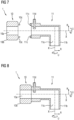
- Fig. 7 shows a longitudinal section through a media guide coupling 1 according to the invention according to a fourth embodiment in the separated state.
- Fig. 8 shows the representation of the Figure 7 in the connected state.
- the fourth embodiment represents a combination of the second and third embodiments.
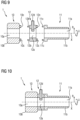
- Fig. 9 shows a longitudinal section through a media guide coupling 1 according to the invention according to a fifth embodiment in the separated state.
- Fig. 10 shows the representation of the Figure 9 in the connected state.
- the two coupling elements 10, 11 do not have any sensor receptacles 10d, 11d.
- the modular hose coupling 1 is designed in three parts, in that a corresponding sensor element 12 is arranged along the longitudinal axis X between the two external coupling elements 10, 11.
- the sensor element 12 has a corresponding flow opening 12a and a first Connecting element 12b and to the right a second connecting element 12c to be connected to the second connecting elements 10c, 11c of the two coupling elements 10, 11 as previously described.
- the sensor element 12 also has a sensor receptacle 12d.
- the two coupling elements 10, 11 can be selected to match the respective other media-carrying devices 2 depending on the application.
- the sensor element 12 can also be selected to match the respective sensor 3. This can simplify or expand the modularity options.
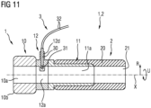
- Fig. 11 shows a longitudinal section through a media guide 1, 2 according to the invention with the media guide coupling 1 of the fifth embodiment.
- a hose 2 as the second media-conducting device 2 or its wall 20 is pulled over the first connecting element 11b of the second coupling element 11 and thus connected to the first connecting element 11b of the second coupling element 11, so that a flow opening 21 of the hose 2 coincides with the flow opening 10a, 11a, 12a of the hose coupling 1.
- a sensor 3 in the form of a temperature sensor 3 is received by the sensor receptacle 12d of the sensor element 12.
- a sensor probe 31 in the form of an NTC thermistor 31 projects all the way inwards or downwards into the sensor receptacle 12d and is held by a sensor housing 30 and connected to a sensor cable 32 in order to make the sensor values available to the outside.
Landscapes
- Engineering & Computer Science (AREA)
- General Engineering & Computer Science (AREA)
- Mechanical Engineering (AREA)
- Physics & Mathematics (AREA)
- General Physics & Mathematics (AREA)
- Quick-Acting Or Multi-Walled Pipe Joints (AREA)
Claims (9)
- Accouplement de guidage de fluide (1)avec un premier élément d'accouplement (10)avec une ouverture de passage (10a) pour guider un fluide à travers celle-ci, et avec un premier élément de liaison (10b) pour la liaison à un deuxième dispositif de guidage de fluide (2), de préférence à un tuyau (2), un tube (2) ou un groupe, etavec un deuxième élément d'accouplement (11)avec une ouverture de passage (11a) pour guider le fluide à travers celle-ci, et avec un premier élément de liaison (11b) pour la liaison à un troisième dispositif de guidage de fluide, de préférence à un tuyau, un tube ou un groupe,les deux éléments d'accouplement (10, 11) étant reliés l'un à l'autre de manière étanche au fluide de telle sorte que leurs ouvertures de passage (10a, 11a) forment une ouverture de passage commune (10a, 11a) de l'accouplement de guidage de fluide (1), etle premier élément d'accouplement (10) présentant un logement de capteur (10d) et/ou le deuxième élément d'accouplement (11) présentant un logement de capteur (11d),caractérisé en ce quele premier élément d'accouplement (10) présente un deuxième élément de liaison (10c),le deuxième élément d'accouplement (11) présentant un deuxième élément de liaison (11c), etle premier élément d'accouplement (10) et le deuxième élément d'accouplement (11) étant reliés l'un à l'autre de manière étanche au fluide au moyen de leurs deuxièmes éléments de liaison (10c, 11c) par encliquetage, clipsage ou vissage.
- Accouplement de guidage de fluide (1) selon la revendication 1,
un élément d'étanchéité, de préférence un joint torique, étant agencé entre les deux deuxièmes éléments de liaison (10c, 11c). - Accouplement de guidage de fluide (1) selon l'une quelconque des revendications précédentes,
l'élément d'accouplement (10, 11) sans logement de capteur (10d, 11d) étant réalisé sous forme de pièce moulée par injection renforcée par des fibres. - Accouplement de guidage de fluide (1)avec un premier élément d'accouplement (10)avec une ouverture de passage (10a) pour guider un fluide à travers celle-ci, et avec un premier élément de liaison (10b) pour la liaison à un deuxième dispositif de guidage de fluide (2), de préférence à un tuyau (2), un tube (2) ou un groupe, avec un deuxième élément d'accouplement (11)avec une ouverture de passage (11a) pour guider le fluide à travers celle-ci, et avec un premier élément de liaison (11b) pour la liaison à un troisième dispositif de guidage de fluide, de préférence à un tuyau, un tube ou un groupe, etavec un élément capteur (12)avec une ouverture de passage (12a) pour guider le fluide à travers celle-ci,le premier élément d'accouplement (10) avec l'élément capteur (12) et l'élément capteur (12) avec le deuxième élément d'accouplement (11) étant reliés l'un à l'autre de manière étanche au fluide de telle sorte que leurs passages (10a, 11a, 12a) forment une ouverture de passage commune (10a, 11a, 12a) de l'accouplement de guidage de fluide (1), etl'élément capteur (12) présentant un logement de capteur (12d),caractérisé en ce quele premier élément d'accouplement (10) et/ou le deuxième élément d'accouplement (11) présentent un deuxième élément de liaison (10c, 11c), l'élément capteur (12) présentant un premier élément de liaison (12b), de préférence et un deuxième élément de liaison (12c), et le premier élément d'accouplement (10) et/ou le deuxième élément d'accouplement (11) étant reliés de manière étanche au fluide à l'élément ou aux éléments de liaison (12b, 12c) de l'élément capteur (12) au moyen de leurs deuxièmes éléments de liaison (10c, 11c) par encliquetage, clipsage ou vissage.
- Accouplement de guidage de fluide (1) selon la revendication 4,
un élément d'étanchéité, de préférence un joint torique, étant agencé entre les éléments de liaison (10c, 11c, 12b, 12c) (respectivement). - Accouplement de guidage de fluide (1) selon l'une quelconque des revendications 4 à 5,
le premier élément d'accouplement (10) et/ou le deuxième élément d'accouplement (11) étant réalisé(s) sous forme de pièce moulée par injection renforcée par des fibres. - Accouplement de guidage de fluide (1) selon l'une quelconque des revendications précédentes,
le premier élément de liaison (10b) du premier élément d'accouplement (10) et le premier élément de liaison (11b) du deuxième élément d'accouplement (11) étant réalisés avec des mécanismes de liaison identiques ou différents. - Accouplement de guidage de fluide (1) selon l'une quelconque des revendications précédentes,
le logement de capteur (10d, 11d, 12d) pénétrant au moins par sections, de préférence complètement, de préférence perpendiculairement à l'ouverture de passage (10a, 11a, 12a), dans l'ouverture de passage (10a, 11a, 12a). - Guide de fluide (1,2)avec un accouplement de guidage de fluide (1) selon l'une quelconque des revendications précédentes etavec un deuxième dispositif de guidage de fluide (2), de préférence avec un tuyau (2), un tube (2) ou un groupe.
Applications Claiming Priority (1)
| Application Number | Priority Date | Filing Date | Title |
|---|---|---|---|
| DE102021213687.7A DE102021213687A1 (de) | 2021-12-02 | 2021-12-02 | Medienführungskupplung |
Publications (2)
| Publication Number | Publication Date |
|---|---|
| EP4191111A1 EP4191111A1 (fr) | 2023-06-07 |
| EP4191111B1 true EP4191111B1 (fr) | 2024-12-11 |
Family
ID=83898035
Family Applications (1)
| Application Number | Title | Priority Date | Filing Date |
|---|---|---|---|
| EP22201816.0A Active EP4191111B1 (fr) | 2021-12-02 | 2022-10-17 | Couplage de guidage de média et guidage de média |
Country Status (2)
| Country | Link |
|---|---|
| EP (1) | EP4191111B1 (fr) |
| DE (1) | DE102021213687A1 (fr) |
Family Cites Families (3)
| Publication number | Priority date | Publication date | Assignee | Title |
|---|---|---|---|---|
| DE102010006766A1 (de) * | 2010-02-04 | 2011-08-04 | A. Raymond Et Cie | Fluidleitungselement |
| DE102014005817A1 (de) * | 2014-04-24 | 2015-10-29 | Voss Automotive Gmbh | Mehrteilige beheizbare Medienleitung, Leitungsverbindungseinrichtung für eine solche sowie Verfahren zum Herstellen einer solchen |
| DE102019208375A1 (de) * | 2019-06-07 | 2020-12-10 | CONTITECH KüHNER GMBH & CIE KG | Rohr mit Flansch |
-
2021
- 2021-12-02 DE DE102021213687.7A patent/DE102021213687A1/de active Pending
-
2022
- 2022-10-17 EP EP22201816.0A patent/EP4191111B1/fr active Active
Also Published As
| Publication number | Publication date |
|---|---|
| EP4191111A1 (fr) | 2023-06-07 |
| DE102021213687A1 (de) | 2023-06-07 |
Similar Documents
| Publication | Publication Date | Title |
|---|---|---|
| DE69634011T2 (de) | Verbindungsherstellung und herstellungsverfahren | |
| DE10029186C2 (de) | Temperatur-Messvorrichtung | |
| EP1169202B1 (fr) | Dispositif pour mesurer une pression de fluide | |
| DE3903551C2 (de) | Verbindungsteil einer Leitungskupplung | |
| DE102012018423A1 (de) | Verbindungselement für einen beheizbaren Schlauch | |
| DE102005002907A1 (de) | Magnetisch-induktives Durchflussmessgerät | |
| DE112006003344T5 (de) | Anschluss für eine Kopplungsvorrichtung für Fluidtransfer | |
| EP0876564B1 (fr) | Raccord de tuyaux | |
| EP4191111B1 (fr) | Couplage de guidage de média et guidage de média | |
| EP2072967A1 (fr) | Capteur électronique et procédé de fabrication d'un capteur | |
| DE102011088736A1 (de) | Einbauarmatur mit einer Dichtungsvorrichtung | |
| EP4038352B1 (fr) | Adaptateur hygiénique pour instrument de terrain | |
| DE102008051303A1 (de) | Verschlusskupplung | |
| EP3591268B1 (fr) | Connecteur de conduite de fluide pourvu de pièce d'insertion fixe destinée à l'étranglement | |
| EP2895779B1 (fr) | Dispositif pour relier deux conduites transportant du fluide | |
| WO2023051880A1 (fr) | Système de guidage de milieu comportant un guide de milieu et doté d'un capteur de température | |
| DE202020106224U1 (de) | Sensorsystem | |
| DE102018129781A1 (de) | Messrohr für ein Messgerät sowie Verfahren zu dessen Herstellung | |
| DE20318857U1 (de) | Fluidleitungsverbindungsanordnung | |
| DE102009017335A1 (de) | Vorrichtung zur Messung des Volumen- oder Massestromes eines Mediums, Maschine mit entsprechender Vorrichtung | |
| DE102014001640B4 (de) | Druck- und Temperatursensor-Element | |
| DE102018115854A1 (de) | Metallische Rohrleitungsanordnung mit generativ hergestelltem Anschlussteil | |
| DE10227373B4 (de) | Rohrförmige Staudrucksonde | |
| EP4113082B1 (fr) | Capteur de température | |
| EP4399494B1 (fr) | Dispositif d'écoulement devant être agencé sur une ligne de conduite de fluide et fixé à un débitmètre, et utilisation d'un dispositif d'écoulement |
Legal Events
| Date | Code | Title | Description |
|---|---|---|---|
| PUAI | Public reference made under article 153(3) epc to a published international application that has entered the european phase |
Free format text: ORIGINAL CODE: 0009012 |
|
| STAA | Information on the status of an ep patent application or granted ep patent |
Free format text: STATUS: THE APPLICATION HAS BEEN PUBLISHED |
|
| AK | Designated contracting states |
Kind code of ref document: A1 Designated state(s): AL AT BE BG CH CY CZ DE DK EE ES FI FR GB GR HR HU IE IS IT LI LT LU LV MC ME MK MT NL NO PL PT RO RS SE SI SK SM TR |
|
| STAA | Information on the status of an ep patent application or granted ep patent |
Free format text: STATUS: REQUEST FOR EXAMINATION WAS MADE |
|
| 17P | Request for examination filed |
Effective date: 20231207 |
|
| RBV | Designated contracting states (corrected) |
Designated state(s): AL AT BE BG CH CY CZ DE DK EE ES FI FR GB GR HR HU IE IS IT LI LT LU LV MC ME MK MT NL NO PL PT RO RS SE SI SK SM TR |
|
| GRAP | Despatch of communication of intention to grant a patent |
Free format text: ORIGINAL CODE: EPIDOSNIGR1 |
|
| STAA | Information on the status of an ep patent application or granted ep patent |
Free format text: STATUS: GRANT OF PATENT IS INTENDED |
|
| RIC1 | Information provided on ipc code assigned before grant |
Ipc: G01K 13/02 20210101ALI20240424BHEP Ipc: G01K 1/14 20210101ALI20240424BHEP Ipc: F16L 41/00 20060101ALI20240424BHEP Ipc: F16L 37/084 20060101ALI20240424BHEP Ipc: F16L 33/30 20060101ALI20240424BHEP Ipc: F16L 13/10 20060101ALI20240424BHEP Ipc: F16L 13/02 20060101AFI20240424BHEP |
|
| INTG | Intention to grant announced |
Effective date: 20240513 |
|
| P01 | Opt-out of the competence of the unified patent court (upc) registered |
Free format text: CASE NUMBER: APP_44358/2024 Effective date: 20240730 |
|
| GRAS | Grant fee paid |
Free format text: ORIGINAL CODE: EPIDOSNIGR3 |
|
| GRAA | (expected) grant |
Free format text: ORIGINAL CODE: 0009210 |
|
| STAA | Information on the status of an ep patent application or granted ep patent |
Free format text: STATUS: THE PATENT HAS BEEN GRANTED |
|
| AK | Designated contracting states |
Kind code of ref document: B1 Designated state(s): AL AT BE BG CH CY CZ DE DK EE ES FI FR GB GR HR HU IE IS IT LI LT LU LV MC ME MK MT NL NO PL PT RO RS SE SI SK SM TR |
|
| REG | Reference to a national code |
Ref country code: GB Ref legal event code: FG4D Free format text: NOT ENGLISH |
|
| REG | Reference to a national code |
Ref country code: CH Ref legal event code: EP |
|
| REG | Reference to a national code |
Ref country code: DE Ref legal event code: R096 Ref document number: 502022002366 Country of ref document: DE |
|
| REG | Reference to a national code |
Ref country code: IE Ref legal event code: FG4D Free format text: LANGUAGE OF EP DOCUMENT: GERMAN |
|
| REG | Reference to a national code |
Ref country code: LT Ref legal event code: MG9D |
|
| PG25 | Lapsed in a contracting state [announced via postgrant information from national office to epo] |
Ref country code: HR Free format text: LAPSE BECAUSE OF FAILURE TO SUBMIT A TRANSLATION OF THE DESCRIPTION OR TO PAY THE FEE WITHIN THE PRESCRIBED TIME-LIMIT Effective date: 20241211 |
|
| PG25 | Lapsed in a contracting state [announced via postgrant information from national office to epo] |
Ref country code: FI Free format text: LAPSE BECAUSE OF FAILURE TO SUBMIT A TRANSLATION OF THE DESCRIPTION OR TO PAY THE FEE WITHIN THE PRESCRIBED TIME-LIMIT Effective date: 20241211 |
|
| PG25 | Lapsed in a contracting state [announced via postgrant information from national office to epo] |
Ref country code: BG Free format text: LAPSE BECAUSE OF FAILURE TO SUBMIT A TRANSLATION OF THE DESCRIPTION OR TO PAY THE FEE WITHIN THE PRESCRIBED TIME-LIMIT Effective date: 20241211 |
|
| REG | Reference to a national code |
Ref country code: NL Ref legal event code: MP Effective date: 20241211 |
|
| PG25 | Lapsed in a contracting state [announced via postgrant information from national office to epo] |
Ref country code: ES Free format text: LAPSE BECAUSE OF FAILURE TO SUBMIT A TRANSLATION OF THE DESCRIPTION OR TO PAY THE FEE WITHIN THE PRESCRIBED TIME-LIMIT Effective date: 20241211 |
|
| PG25 | Lapsed in a contracting state [announced via postgrant information from national office to epo] |
Ref country code: NO Free format text: LAPSE BECAUSE OF FAILURE TO SUBMIT A TRANSLATION OF THE DESCRIPTION OR TO PAY THE FEE WITHIN THE PRESCRIBED TIME-LIMIT Effective date: 20250311 |
|
| PG25 | Lapsed in a contracting state [announced via postgrant information from national office to epo] |
Ref country code: LV Free format text: LAPSE BECAUSE OF FAILURE TO SUBMIT A TRANSLATION OF THE DESCRIPTION OR TO PAY THE FEE WITHIN THE PRESCRIBED TIME-LIMIT Effective date: 20241211 Ref country code: GR Free format text: LAPSE BECAUSE OF FAILURE TO SUBMIT A TRANSLATION OF THE DESCRIPTION OR TO PAY THE FEE WITHIN THE PRESCRIBED TIME-LIMIT Effective date: 20250312 |
|
| PG25 | Lapsed in a contracting state [announced via postgrant information from national office to epo] |
Ref country code: RS Free format text: LAPSE BECAUSE OF FAILURE TO SUBMIT A TRANSLATION OF THE DESCRIPTION OR TO PAY THE FEE WITHIN THE PRESCRIBED TIME-LIMIT Effective date: 20250311 |
|
| PG25 | Lapsed in a contracting state [announced via postgrant information from national office to epo] |
Ref country code: NL Free format text: LAPSE BECAUSE OF FAILURE TO SUBMIT A TRANSLATION OF THE DESCRIPTION OR TO PAY THE FEE WITHIN THE PRESCRIBED TIME-LIMIT Effective date: 20241211 |
|
| PG25 | Lapsed in a contracting state [announced via postgrant information from national office to epo] |
Ref country code: SM Free format text: LAPSE BECAUSE OF FAILURE TO SUBMIT A TRANSLATION OF THE DESCRIPTION OR TO PAY THE FEE WITHIN THE PRESCRIBED TIME-LIMIT Effective date: 20241211 |
|
| PG25 | Lapsed in a contracting state [announced via postgrant information from national office to epo] |
Ref country code: PL Free format text: LAPSE BECAUSE OF FAILURE TO SUBMIT A TRANSLATION OF THE DESCRIPTION OR TO PAY THE FEE WITHIN THE PRESCRIBED TIME-LIMIT Effective date: 20241211 |
|
| PG25 | Lapsed in a contracting state [announced via postgrant information from national office to epo] |
Ref country code: IS Free format text: LAPSE BECAUSE OF FAILURE TO SUBMIT A TRANSLATION OF THE DESCRIPTION OR TO PAY THE FEE WITHIN THE PRESCRIBED TIME-LIMIT Effective date: 20250411 |
|
| PG25 | Lapsed in a contracting state [announced via postgrant information from national office to epo] |
Ref country code: PT Free format text: LAPSE BECAUSE OF FAILURE TO SUBMIT A TRANSLATION OF THE DESCRIPTION OR TO PAY THE FEE WITHIN THE PRESCRIBED TIME-LIMIT Effective date: 20250411 |
|
| PG25 | Lapsed in a contracting state [announced via postgrant information from national office to epo] |
Ref country code: EE Free format text: LAPSE BECAUSE OF FAILURE TO SUBMIT A TRANSLATION OF THE DESCRIPTION OR TO PAY THE FEE WITHIN THE PRESCRIBED TIME-LIMIT Effective date: 20241211 |
|
| PG25 | Lapsed in a contracting state [announced via postgrant information from national office to epo] |
Ref country code: RO Free format text: LAPSE BECAUSE OF FAILURE TO SUBMIT A TRANSLATION OF THE DESCRIPTION OR TO PAY THE FEE WITHIN THE PRESCRIBED TIME-LIMIT Effective date: 20241211 |
|
| PG25 | Lapsed in a contracting state [announced via postgrant information from national office to epo] |
Ref country code: SK Free format text: LAPSE BECAUSE OF FAILURE TO SUBMIT A TRANSLATION OF THE DESCRIPTION OR TO PAY THE FEE WITHIN THE PRESCRIBED TIME-LIMIT Effective date: 20241211 |
|
| PG25 | Lapsed in a contracting state [announced via postgrant information from national office to epo] |
Ref country code: CZ Free format text: LAPSE BECAUSE OF FAILURE TO SUBMIT A TRANSLATION OF THE DESCRIPTION OR TO PAY THE FEE WITHIN THE PRESCRIBED TIME-LIMIT Effective date: 20241211 |
|
| PG25 | Lapsed in a contracting state [announced via postgrant information from national office to epo] |
Ref country code: IT Free format text: LAPSE BECAUSE OF FAILURE TO SUBMIT A TRANSLATION OF THE DESCRIPTION OR TO PAY THE FEE WITHIN THE PRESCRIBED TIME-LIMIT Effective date: 20241211 |
|
| PG25 | Lapsed in a contracting state [announced via postgrant information from national office to epo] |
Ref country code: SE Free format text: LAPSE BECAUSE OF FAILURE TO SUBMIT A TRANSLATION OF THE DESCRIPTION OR TO PAY THE FEE WITHIN THE PRESCRIBED TIME-LIMIT Effective date: 20241211 |
|
| REG | Reference to a national code |
Ref country code: DE Ref legal event code: R097 Ref document number: 502022002366 Country of ref document: DE |
|
| PG25 | Lapsed in a contracting state [announced via postgrant information from national office to epo] |
Ref country code: DK Free format text: LAPSE BECAUSE OF FAILURE TO SUBMIT A TRANSLATION OF THE DESCRIPTION OR TO PAY THE FEE WITHIN THE PRESCRIBED TIME-LIMIT Effective date: 20241211 |
|
| PLBE | No opposition filed within time limit |
Free format text: ORIGINAL CODE: 0009261 |
|
| STAA | Information on the status of an ep patent application or granted ep patent |
Free format text: STATUS: NO OPPOSITION FILED WITHIN TIME LIMIT |
|
| 26N | No opposition filed |
Effective date: 20250912 |
|
| PGFP | Annual fee paid to national office [announced via postgrant information from national office to epo] |
Ref country code: DE Payment date: 20251020 Year of fee payment: 4 |
|
| PGFP | Annual fee paid to national office [announced via postgrant information from national office to epo] |
Ref country code: AT Payment date: 20260113 Year of fee payment: 4 |
|
| PGFP | Annual fee paid to national office [announced via postgrant information from national office to epo] |
Ref country code: FR Payment date: 20251029 Year of fee payment: 4 |