EP2242146A2 - Clamp structure and load connecting block or separator with clamp structure - Google Patents
Clamp structure and load connecting block or separator with clamp structure Download PDFInfo
- Publication number
- EP2242146A2 EP2242146A2 EP10160092A EP10160092A EP2242146A2 EP 2242146 A2 EP2242146 A2 EP 2242146A2 EP 10160092 A EP10160092 A EP 10160092A EP 10160092 A EP10160092 A EP 10160092A EP 2242146 A2 EP2242146 A2 EP 2242146A2
- Authority
- EP
- European Patent Office
- Prior art keywords
- cage
- clamping
- yoke
- clamping structure
- recess
- Prior art date
- Legal status (The legal status is an assumption and is not a legal conclusion. Google has not performed a legal analysis and makes no representation as to the accuracy of the status listed.)
- Granted
Links
Images


Classifications
-
- H—ELECTRICITY
- H01—ELECTRIC ELEMENTS
- H01R—ELECTRICALLY-CONDUCTIVE CONNECTIONS; STRUCTURAL ASSOCIATIONS OF A PLURALITY OF MUTUALLY-INSULATED ELECTRICAL CONNECTING ELEMENTS; COUPLING DEVICES; CURRENT COLLECTORS
- H01R4/00—Electrically-conductive connections between two or more conductive members in direct contact, i.e. touching one another; Means for effecting or maintaining such contact; Electrically-conductive connections having two or more spaced connecting locations for conductors and using contact members penetrating insulation
- H01R4/28—Clamped connections, spring connections
- H01R4/30—Clamped connections, spring connections utilising a screw or nut clamping member
- H01R4/36—Conductive members located under tip of screw
- H01R4/363—Conductive members located under tip of screw with intermediate part between tip and conductive member
- H01R4/366—Conductive members located under tip of screw with intermediate part between tip and conductive member intermediate part attached to the tip of the screw
-
- H—ELECTRICITY
- H01—ELECTRIC ELEMENTS
- H01R—ELECTRICALLY-CONDUCTIVE CONNECTIONS; STRUCTURAL ASSOCIATIONS OF A PLURALITY OF MUTUALLY-INSULATED ELECTRICAL CONNECTING ELEMENTS; COUPLING DEVICES; CURRENT COLLECTORS
- H01R9/00—Structural associations of a plurality of mutually-insulated electrical connecting elements, e.g. terminal strips or terminal blocks; Terminals or binding posts mounted upon a base or in a case; Bases therefor
- H01R9/22—Bases, e.g. strip, block, panel
- H01R9/24—Terminal blocks
Definitions
- the present invention relates to a clamping structure for connecting cables to connecting rails and load-switching strips or disconnectors with such a clamping structure.
- Such a clamp construction is known, for example from the DE 44 35 057 ,
- the clamping structure described there has a closed clamping cage, through the bridge of a pressure pin accesses a pressure piece, so that with the help of the pressure piece after both terminal rail and cable have been arranged in the terminal cage, the cable can be pressed against the terminal rail.
- This clamping structure is intended for use on V-shaped connecting rails. It can not be used on flat connecting rails.
- the insertion of the cable in the terminal cage is very difficult to accomplish, especially for large cable cross-sections.
- the clamping cage To connect a cable to the connecting rail, the clamping cage must first be pushed onto the connecting rail or onto the cable. Then the corresponding cable must be brought in the direction of the axis of the connecting rail in the clamping cage. Only then you can clamp the pressure piece with the help of the pressure bolt on the one hand, and connecting rail on the other hand in the clamping cage.
- cables with large cross sections often have a very large bending radius. If these cables have already been assembled and routed, they usually can not be different in the longitudinal direction.
- the cable Although they can be moved transversely to the cable direction, e.g. However, a longitudinal displacement is usually not possible. Therefore, in order to connect with the aid of the described clamping structure, the cable must first be raised in the transverse direction and then bent accordingly in order to thread the cable end into the clamping cage. This bending, however, is difficult or impossible to accomplish with cables having large cable cross-sections.
- Another disadvantage of the known clamping structure is that the axial position of the clamping structure is not fixed. In other words, the clamping structure can be moved in the direction of the busbar axis or the cable axis during assembly. This can cause the terminal structure with other adjacent components comes into undesirable contact or that connecting rail or cable are no longer optimally clamped in the clamping cage. This is the case, for example, with some connection bars for disconnectors or safety edges customary to provide the connecting rail with a V-shaped connecting portion, which adjoins a substantially flat band-shaped portion.
- the clamping structure for this purpose has a substantially U-shaped cage bracket, which has two leg portions and a bottom portion connecting the leg portions, a cage yoke which substantially at the side facing away from the bottom portion of the leg portions connects to each other, so that between the cage yoke on the one hand and cage bracket on the other a cage cell is formed, a clamping piece disposed between the two leg portions in the cage cell, and a clamping plate disposed within the cage cell between the cage yoke and clamping piece, the clamping plate being reciprocable between an open position and a clamping position, and wherein the cage yoke from the cage bracket is removable.
- the clamping plate is connected to a threaded pin and the cage yoke has a threaded bore for receiving the threaded pin, so that when recorded in the threaded bore of the cage yoke threaded pin, the clamping plate can be brought by turning the threaded pin from the open position to a clamping position.
- This measure has the advantage that the clamping plate can be moved perpendicular to the cable axis by simply turning the threaded pin, which may be formed for example as a screw.
- by connecting the clamping plate with the threaded pin ensures that during disassembly by turning the grub screw in the opposite direction, the clamping plate can be easily detached from the cable.
- the pressure piece is not connected to the corresponding pressure pin, so that the pressure piece from the cable can not be solved by means of the pressure bolt, but must be removed manually during disassembly of this from the clamping cage.
- a terminal space for receiving a connecting rail is provided between the clamping piece and the bottom portion of the cage bracket.
- the clamping piece divides the cage cell into a terminal space and a cable space so that the clamping piece is arranged between the cable and the terminal rail.
- the clamping piece may be concave on its side facing the cable, so that the clamping piece better adapts to the outer contour of the cable, while the side facing away from the cable of the clamping piece can be adapted to the shape of the connecting rail.
- the clamping structure it is possible with the aid of the clamping structure to fix a cable to a connecting rail, which is originally provided for connection to the cable via corresponding pole shoes, which are screwed to the connecting rail.
- the two leg portions are formed cranked, so that the two leg sections at the end facing away from the bottom portion each have a projecting in the direction of the other leg portion portion, wherein the distance between the two projecting portions of the leg portions is smaller than the length of Käfigjochs, so that the cage yoke can not be removed or only by a bending apart of the leg portions of the bottom portion away from the cage bracket.
- This embodiment facilitates for some applications, the assembly and disassembly of the cable to the connecting rails.
- At least one leg section has a projection on its side facing the other leg section. This projection serves to hold the cage yoke in its substantially opposite to the bottom portion position of the leg portions. The cage yoke can be easily removed if the leg sections are bent slightly outwards.
- a leg portion may have a substantially U-shaped through hole surrounding a tongue portion, with the tongue portion toward the other Leg portion is bent and forms the projection.
- This can be formed in a cost effective manner, the projection. It is possible, for example, to form the cage bracket as a stamped and bent part.
- the object is achieved in that a corresponding terminal structure is provided in the load switch bar or the disconnector.
- the load switch bar or the separator may have a connection rail associated recess into which a push insert is inserted, wherein the push insert has a recess for receiving the clamping structure.
- the clamping structure is first inserted into the recess of the push insert.
- the push insert is inserted together with the terminal structure in the corresponding recess of the load switch bar or the disconnector.
- the recess in the connecting rail is designed such that when inserting the push insert, the connecting rail extends into the terminal space of the clamping structure. Now, only the cable must be applied to the clamping piece and the clamping plate are brought into the clamping position.
- the push insert on a stop element, which prevents a displacement of the clamping structure relative to the push insert in the direction of the recess or in the opposite direction.
- a stop element which prevents a displacement of the clamping structure relative to the push insert in the direction of the recess or in the opposite direction.
- two stop elements are provided which receive the clamping structure such that a relative movement in the direction of the recess and in the opposite direction is prevented.
- the push insert and / or the recess in the load switch bar or the separator has a movable or deformable locking element and the recess in the load switch bar or the separator and / or the push insert has a recess for receiving the latching element.
- the push insert is pushed into the corresponding recess until the locking element engages in the recess. Now the push insert is in the exact position and the assembly can be done.
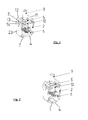
- FIG. 1 a first embodiment of a clamping structure according to the invention is shown.
- the clamping structure has a substantially U-shaped cage bracket 1, which has two leg sections 2, 3 and a bottom section 4 connecting the leg sections 2, 3. Furthermore, a cage yoke 5 is provided, which substantially at the side facing away from the bottom portion 4 of the leg sections 2, 3 connects to each other, so that between the cage yoke 5 on the one hand and cage bracket 1 on the other hand, a space is formed, which is also called cage cell below.
- a clamping piece 6 is arranged between the two leg sections 2, 3. This clamping piece 6 divides the cage cell into a terminal space 7 for a connecting rail and a cable space 8 for receiving the cable.
- connection space 7 is essentially limited by the clamping piece 6 and the bottom portion 4, while the cable space 8 is bounded by the clamping piece 6, the two leg portions 2, 3 and the cage yoke 5.
- the cage yoke 5 has a threaded through bore through which a threaded pin 9 is connected to a clamping plate 10 which is arranged in the cable space 8. By turning the threaded pin 9, the clamping plate 10 can be moved in the direction of the clamping piece 6 or away from it.
- the two leg sections 2, 3 have two cranked sections 11, 12 at their end facing away from the bottom section 4. These cranked portions 11, 12 are formed such that the distance between them is slightly smaller than the corresponding extent of the cage yoke 5, so that in the in FIG.
- both legs have an approximately U-shaped recess 13 which surrounds a corresponding tongue portion 14.
- This tongue portion 14 has been bent in the production something in the direction of the cage cell, so that in the in FIG. 1 shown position the cage yoke 5 on both sides of the corresponding tongue portion 14 is supported.
- the leg sections must be bent slightly outwards, or the cage yoke must be pushed forward (or rearward).
- the in FIG. 1 shown embodiment is provided for connection to substantially flat connecting rails, therefore, the terminal compartment 7 is formed according to the rail shape.
- FIG. 2 therefore, another embodiment is shown which differs from the embodiment of FIG. 1 essentially differs in that clamping piece 6 on the one hand and bottom section 4 on the other hand are deviating shaped to receive a substantially V-shaped connecting rail.
- the clamping piece 6 is provided between the connecting rail and cable, so that the clamping piece 6 may be formed concave on its side facing the cable space to adapt to the shape of the cable, and at the terminal space side facing the expected shape of the Connecting rail can be formed.
- FIG. 3 an embodiment of a push insert is shown.
- the push insert 15 has a recess 16, in which the bottom portion 4 of the clamping structure can be used.
- the recess 16 is bounded by lateral cheeks 18, 19 and a front stop surface 17.
- the push insert on two locking elements 20 which are elastically deformable.
- the push insert 15 has a recess 21 for receiving a fastening nut. If the push insert together with the in FIG. 1 used clamp construction, so it is not necessary to arrange a nut in the recess 21.
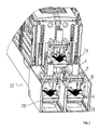
- FIG. 4 is a perspective view of a corresponding switching strip 22 is shown.
- This switching strip 22 has three connecting rails, which must be connected with appropriate cables. Therefore, refer to the corresponding connection bars in the in FIG. 4 already shown the corresponding U-shaped cage bracket 1, 1 'and 1 "placed
- FIG. 5 is another perspective view of the switching strip 22 can be seen. In this view, the substantially band-shaped connecting rails 23 are clearly visible. These are already arranged in the corresponding connection space 7 of the clamping structure.
- the cage yoke 5 is mounted on the cage bracket 1.
- the cables can either be in the in FIG. 5 shown position or in the FIG. 4 Position are introduced into the cage cell.
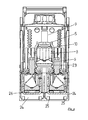
- FIG. 6 shows a sectional view through the embodiment of FIG.
- the insertion direction is in FIG. 3 marked with an arrow.
- the corresponding locking elements 20 then engage in corresponding recesses 25 in the recess 24 of the switching strip 22, so that the push insert 15 is positioned relative to the switching strip 22.
- the clamping structure has exactly the correct position in the FIGS. 4 to 6 is shown.
- the cable if necessary, after previous removal of the cage yoke 5, are easily introduced into the cable space 8.
- the clamping plate 10 can then be moved in the direction of the clamping piece 6, so that the cable is securely clamped securely in the cable compartment 8 and the connecting rail 23 in the terminal compartment 7.
- the connecting rails are designed to be used with pole pieces.
- the clamping structure 1 together with the push insert 15 is pulled out of the recess 24.
- the clamp assembly is removed and a nut inserted into the corresponding recess 21 of the drawer insert 15.
- the push insert 15 can be inserted again into the corresponding recess 24.
- the connecting rails 23 already have through holes 26, so that it is easily possible to put the pole pieces on the nut received in the recess 21 and by means of a screw which passes through both pole piece and through hole 26 in the connecting rail 23, with the mother in connect the recess 21 and thus to connect the cable lugs firmly to the connecting rail.
Landscapes
- Installation Of Indoor Wiring (AREA)
- Connections Arranged To Contact A Plurality Of Conductors (AREA)
- Details Of Indoor Wiring (AREA)
Abstract
Description
Die vorliegende Erfindung betrifft einen Klemmaufbau zum Anschließen von Kabeln an Anschlußschienen sowie Lastschaltleisten oder Trenner mit einem solchen Klemmaufbau.The present invention relates to a clamping structure for connecting cables to connecting rails and load-switching strips or disconnectors with such a clamping structure.
Ein solcher Klemmaufbau ist beispielsweise bekannt aus der
Dieser Klemmaufbau ist für die Verwendung an V-förmigen Anschlußschienen vorgesehen. Er kann nicht an flach ausgebildeten Anschlußschienen verwendet werden. Zudem ist das Einlegen des Kabels in den Klemmkäfig insbesondere bei großen Kabelquerschnitten nur sehr schwer zu bewerkstelligen. Für den Anschluß eines Kabels an die Anschlußschiene muß zunächst der Klemmkäfig auf die Anschlußschiene oder auf das Kabel geschoben werden. Dann muß das entsprechende Kabel in Richtung der Achse der Anschlußschiene in den Klemmkäfig gebracht werden. Erst dann kann man das Druckstück mit Hilfe des Druckbolzens an Kabel einerseits und Anschlußschiene andererseits im Klemmkäfig festklemmen. Kabel mit großen Querschnitten haben jedoch häufig einen sehr großen Biegeradius. Sind diese Kabel bereits entsprechend konfektioniert und verlegt, lassen sie sich in Längsrichtung in der Regel nicht mehr verschieden. Sie können zwar quer zur Kabelrichtung bewegt, z.B. angehoben werden, eine Längsverschiebung ist jedoch in der Regel nicht möglich. Daher muß das Kabel, um es mit Hilfe des beschriebenen Klemmaufbaus anzuschließen, zunächst in Querrichtung angehoben werden und dann entsprechend gebogen werden, um das Kabelende in den Klemmkäfig einzufädeln. Dieses Verbiegen ist jedoch bei Kabeln mit großen Kabelquerschnitten schwer bis gar nicht zu bewerkstelligen.This clamping structure is intended for use on V-shaped connecting rails. It can not be used on flat connecting rails. In addition, the insertion of the cable in the terminal cage is very difficult to accomplish, especially for large cable cross-sections. To connect a cable to the connecting rail, the clamping cage must first be pushed onto the connecting rail or onto the cable. Then the corresponding cable must be brought in the direction of the axis of the connecting rail in the clamping cage. Only then you can clamp the pressure piece with the help of the pressure bolt on the one hand, and connecting rail on the other hand in the clamping cage. However, cables with large cross sections often have a very large bending radius. If these cables have already been assembled and routed, they usually can not be different in the longitudinal direction. Although they can be moved transversely to the cable direction, e.g. However, a longitudinal displacement is usually not possible. Therefore, in order to connect with the aid of the described clamping structure, the cable must first be raised in the transverse direction and then bent accordingly in order to thread the cable end into the clamping cage. This bending, however, is difficult or impossible to accomplish with cables having large cable cross-sections.
Ein weiterer Nachteil des bekannten Klemmaufbaus besteht darin, daß die axiale Position des Klemmaufbaus nicht festgelegt ist. Mit anderen Worten kann der Klemmaufbau in Richtung der Anschlußschienenachse bzw. der Kabelachse bei der Montage verschoben werden. Dies kann dazu führen, daß der Klemmaufbau mit anderen benachbarten Bauteilen in unerwünschten Kontakt kommt oder daß Anschlußschiene oder Kabel nicht mehr optimal im Klemmkäfig geklemmt werden. So ist es beispielsweise bei manchen Anschlußschienen für Trenner oder Schaltleisten üblich, die Anschlußschiene mit einem V-förmigen Anschlußabschnitt zu versehen, der sich an eine im wesentlichen ebene bandförmigen Abschnitt anschließt. Wird nun der Klemmaufbau in axialer Richtung zu weit in Richtung des Trenners bzw. der Schaltleiste verschoben, so kann es vorkommen, daß bereits der bandförmige Abschnitt der Anschlußschiene in den Klemmkäfig gerät, so daß das Kabel mit Hilfe des Druckstücks nicht mehr sicher im Klemmkäfig gehalten wird. Wird diese axiale Fehlanpassung während der Montage übersehen, so kann dies bei der späteren Verwendung der Schaltleiste oder des Trenners zu einem hochohmigen Kontakt und damit zu einer unerwünschten Wärmeentwicklung bis hin zu Entladungsfunken führen.Another disadvantage of the known clamping structure is that the axial position of the clamping structure is not fixed. In other words, the clamping structure can be moved in the direction of the busbar axis or the cable axis during assembly. This can cause the terminal structure with other adjacent components comes into undesirable contact or that connecting rail or cable are no longer optimally clamped in the clamping cage. This is the case, for example, with some connection bars for disconnectors or safety edges customary to provide the connecting rail with a V-shaped connecting portion, which adjoins a substantially flat band-shaped portion. Now, if the clamping structure in the axial direction too far moved in the direction of the disconnector or the switching strip, it may happen that already the band-shaped portion of the connecting rail device in the terminal cage, so that the cable no longer securely held in the clamping cage with the help of the pressure piece becomes. If this axial mismatch is overlooked during assembly, this can lead to a high-resistance contact and thus to undesirable heat generation up to discharge sparks in the later use of the safety edge or the disconnector.
Es ist daher Aufgabe der vorliegenden Erfindung, einen Klemmaufbau zum Anschließen von Kabeln an Anschlußschienen bereitzustellen, der auch bei Kabeln mit großem Kabelquerschnitt einen einfachen Anschluß des Kabels an die Anschlußschiene ermöglicht.It is therefore an object of the present invention to provide a clamping structure for connecting cables to connecting rails, which also allows for cables with a large cable cross-section easy connection of the cable to the connecting rail.
Erfindungsgemäß hat der Klemmaufbau dazu einen im wesentlichen U-förmigen Käfigbügel, der zwei Schenkelabschnitte und einen die Schenkelabschnitte verbindenden Bodenabschnitt aufweist, ein Käfigjoch, welches im wesentlichen an der dem Bodenabschnitt abgewandten Seite der Schenkelabschnitte diese miteinander verbindet, so daß zwischen Käfigjoch einerseits und Käfigbügel andererseits eine Käfigzelle gebildet wird, ein zwischen den beiden Schenkelabschnitten in der Käfigzelle angeordnetes Klemmstück und eine Klemmplatte, die innerhalb der Käfigzelle zwischen Käfigjoch und Klemmstück angeordnet ist, wobei die Klemmplatte zwischen einer offenen Position und einer Klemmposition hin- und herbewegt werden kann und wobei das Käfigjoch vom Käfigbügel abnehmbar ist.According to the invention, the clamping structure for this purpose has a substantially U-shaped cage bracket, which has two leg portions and a bottom portion connecting the leg portions, a cage yoke which substantially at the side facing away from the bottom portion of the leg portions connects to each other, so that between the cage yoke on the one hand and cage bracket on the other a cage cell is formed, a clamping piece disposed between the two leg portions in the cage cell, and a clamping plate disposed within the cage cell between the cage yoke and clamping piece, the clamping plate being reciprocable between an open position and a clamping position, and wherein the cage yoke from the cage bracket is removable.
Dadurch, daß das Käfigjoch vom Käfigbügel abgenommen werden kann, ist es insbesondere beim Anschluß von Kabeln mit großem Kabelquerschnitt nun einfach möglich, nach Abnahme des Käfigjochs vom Käfigbügel das Kabel von oben, d.h. durch die normalerweise vom Käfigjoch verschlossene Öffnung, in die Käfigzelle zu bringen. Diese Art der Montage hat zudem den Vorteil, daß beim Einfädeln des Kabels in die Käfigzelle der Klemmaufbau im allgemeinen nicht versehentlich in axialer Richtung verschoben wird, so daß die Gefahr einer axialen Fehlausrichtung des Klemmaufbaus verringert wird.The fact that the cage yoke can be removed from the cage bracket, it is now easily possible in particular when connecting cables with a large cable cross-section, after removal of the cage yoke from the cage bracket, the cable from above, i. through the normally closed by the cage yoke opening to bring into the cage cell. This type of assembly also has the advantage that when threading the cable into the cage cell, the clamping structure is generally not accidentally displaced in the axial direction, so that the risk of axial misalignment of the clamping structure is reduced.
In einer bevorzugten Ausführungsform ist die Klemmplatte mit einem Gewindestift verbunden und das Käfigjoch weist eine Gewindebohrung zur Aufnahme des Gewindestifts auf, so daß bei in der Gewindebohrung des Käfigjochs aufgenommenem Gewindestift die Klemmplatte durch Drehen des Gewindestifts von der offenen Position in eine Klemmposition gebracht werden kann. Diese Maßnahme hat zum einen den Vorteil, daß die Klemmplatte durch einfaches Drehen des Gewindestifts, der beispielsweise auch als Schraube ausgebildet sein kann, senkrecht zur Kabelachse bewegt werden kann. Zum anderen wird durch die Verbindung der Klemmplatte mit dem Gewindestift gewährleistet, daß bei der Demontage durch Drehen des Gewindestifts in die entgegengesetzte Richtung die Klemmplatte einfach von dem Kabel gelöst werden kann. Im Gegensatz dazu ist beispielsweise bei der in der eingangs erwähnten
In einer weiteren bevorzugten Ausführungsform ist zwischen Klemmstück und Bodenabschnitt des Käfigbügels ein Anschlußraum zur Aufnahme einer Anschlußschiene vorgesehen. Mit anderen Worten teilt das Klemmstück die Käfigzelle in einen Anschlußraum und einen Kabelraum, so dass das Klemmstück zwischen Kabel und Anschlußschiene angeordnet ist.In a further preferred embodiment, a terminal space for receiving a connecting rail is provided between the clamping piece and the bottom portion of the cage bracket. In other words, the clamping piece divides the cage cell into a terminal space and a cable space so that the clamping piece is arranged between the cable and the terminal rail.
So kann beispielsweise das Klemmstück an seiner dem Kabel zugewandten Seite konkav ausgebildet sein, so daß sich das Klemmstück besser an die Außenkontur des Kabels anpaßt, während die dem Kabel abgewandte Seite des Klemmstücks an die Form der Anschlußschiene angepaßt sein kann.For example, the clamping piece may be concave on its side facing the cable, so that the clamping piece better adapts to the outer contour of the cable, while the side facing away from the cable of the clamping piece can be adapted to the shape of the connecting rail.
Beispielsweise ist es möglich, mit Hilfe des Klemmaufbaus ein Kabel an einer Anschlußschiene zu befestigen, die ursprünglich für eine Verbindung mit dem Kabel über entsprechende Polschuhe, die mit der Anschlußschiene verschraubt werden, vorgesehen ist.For example, it is possible with the aid of the clamping structure to fix a cable to a connecting rail, which is originally provided for connection to the cable via corresponding pole shoes, which are screwed to the connecting rail.
In einer weiteren bevorzugten Ausführungsform sind die beiden Schenkelabschnitte gekröpft ausgebildet, so daß die beiden Schenkelabschnitte an dem dem Bodenabschnitt abgewandten Ende jeweils einen in Richtung des anderen Schenkelabschnitts vorspringenden Abschnitt aufweisen, wobei der Abstand zwischen den beiden vorspringenden Abschnitten der Schenkelabschnitte kleiner ist als die Länge des Käfigjochs, so daß das Käfigjoch nicht oder nur durch ein Auseinanderbiegen der Schenkelabschnitte von dem Bodenabschnitt weg aus dem Käfigbügel entfernt werden kann. Diese Ausführungsform erleichtert für manche Anwendungsfälle die Montage und Demontage der Kabel an den Anschlußschienen.In a further preferred embodiment, the two leg portions are formed cranked, so that the two leg sections at the end facing away from the bottom portion each have a projecting in the direction of the other leg portion portion, wherein the distance between the two projecting portions of the leg portions is smaller than the length of Käfigjochs, so that the cage yoke can not be removed or only by a bending apart of the leg portions of the bottom portion away from the cage bracket. This embodiment facilitates for some applications, the assembly and disassembly of the cable to the connecting rails.
In einer weiteren bevorzugten Ausführungsform weist zumindest ein Schenkelabschnitt an seiner dem anderen Schenkelabschnitt zugewandten Seite einen Vorsprung auf. Dieser Vorsprung dient dazu, das Käfigjoch in seiner im wesentlichen an der dem Bodenabschnitt abgewandten Position der Schenkelabschnitte zu halten. Das Käfigjoch kann leicht entfernt werden, wenn die Schenkelabschnitte leicht nach außen gebogen werden.In a further preferred embodiment, at least one leg section has a projection on its side facing the other leg section. This projection serves to hold the cage yoke in its substantially opposite to the bottom portion position of the leg portions. The cage yoke can be easily removed if the leg sections are bent slightly outwards.
Beispielsweise kann ein Schenkelabschnitt eine im wesentlichen U-förmige Durchgangsöffnung aufweisen, die einen Zungenabschnitt umgibt, wobei der Zungenabschnitt in Richtung des anderen Schenkelabschnitts gebogen ist und den Vorsprung bildet. Dadurch kann auf kostengünstige Weise der Vorsprung ausgebildet werden. Es ist beispielsweise möglich, den Käfigbügel als Stanzbiegeteil auszubilden.For example, a leg portion may have a substantially U-shaped through hole surrounding a tongue portion, with the tongue portion toward the other Leg portion is bent and forms the projection. This can be formed in a cost effective manner, the projection. It is possible, for example, to form the cage bracket as a stamped and bent part.
Hinsichtlich der eingangs genannten Lastschaltleiste oder des Trenners wird die Aufgabe dadurch gelöst, daß in der Lastschaltleiste oder dem Trenner ein entsprechender Klemmaufbau vorgesehen ist.With regard to the load switch bar or the disconnector mentioned above, the object is achieved in that a corresponding terminal structure is provided in the load switch bar or the disconnector.
Dabei kann die Lastschaltleiste oder der Trenner eine der Anschlußschiene zugeordnete Ausnehmung aufweisen, in die ein Schubeinsatz einschiebbar ist, wobei der Schubeinsatz eine Ausnehmung zur Aufnahme der Klemmaufbaus aufweist. Mit anderen Worten wird bei der Montage der Klemmaufbau zunächst in die Ausnehmung des Schubeinsatzes eingesetzt. Dann wird der Schubeinsatz zusammen mit dem Klemmaufbau in die entsprechende Ausnehmung der Lastschaltleiste oder des Trenners eingeschoben. Dabei ist die Ausnehmung in der Anschlußschiene derart ausgebildet, daß beim Einschieben des Schubeinsatzes die Anschlußschiene sich in den Anschlußraum des Klemmaufbaus erstreckt. Nun muß lediglich das Kabel auf das Klemmstück aufgebracht werden und die Klemmplatte in die Klemmposition gebracht werden. In einer bevorzugten Ausführungsform weist der Schubeinsatz ein Anschlagelement auf, das eine Verschiebung des Klemmaufbaus relativ zum Schubeinsatz in Richtung der Ausnehmung oder in der Gegenrichtung verhindert. Vorzugsweise sind zwei Anschlagelemente vorgesehen, die den Klemmaufbau derart aufnehmen, daß eine Relativbewegung in Richtung der Ausnehmung und in der Gegenrichtung verhindert wird. Beim Einschieben des Schubeinsatzes wird daher sichergestellt, daß der Klemmaufbau in der exakten Position in Bezug auf die Anschlußschiene angeordnet ist.In this case, the load switch bar or the separator may have a connection rail associated recess into which a push insert is inserted, wherein the push insert has a recess for receiving the clamping structure. In other words, during assembly, the clamping structure is first inserted into the recess of the push insert. Then the push insert is inserted together with the terminal structure in the corresponding recess of the load switch bar or the disconnector. The recess in the connecting rail is designed such that when inserting the push insert, the connecting rail extends into the terminal space of the clamping structure. Now, only the cable must be applied to the clamping piece and the clamping plate are brought into the clamping position. In a preferred embodiment, the push insert on a stop element, which prevents a displacement of the clamping structure relative to the push insert in the direction of the recess or in the opposite direction. Preferably, two stop elements are provided which receive the clamping structure such that a relative movement in the direction of the recess and in the opposite direction is prevented. When inserting the push insert is therefore ensured that the clamping structure is arranged in the exact position with respect to the connecting rail.
Um ein versehentliches Verschieben des Schubeinsatzes innerhalb der Ausnehmung zu verhindern, ist in einer weiteren bevorzugten Ausführungsform vorgesehen, daß das Schubeinsatz und/oder die Ausnehmung in der Lastschaltleiste oder dem Trenner ein bewegliches oder verformbares Rastelement aufweist und die Ausnehmung in der Lastschaltleiste oder dem Trenner und/oder das Schubeinsatz eine Vertiefung zur Aufnahme des Rastelements aufweist. Mit anderen Worten wird der Schubeinsatz in die entsprechende Ausnehmung geschoben, bis das Rastelement in die Vertiefung einrastet. Nun ist der Schubeinsatz in der exakten Position und die Montage kann erfolgen.In order to prevent accidental displacement of the pusher insert within the recess is provided in a further preferred embodiment that the push insert and / or the recess in the load switch bar or the separator has a movable or deformable locking element and the recess in the load switch bar or the separator and / or the push insert has a recess for receiving the latching element. In other words, the push insert is pushed into the corresponding recess until the locking element engages in the recess. Now the push insert is in the exact position and the assembly can be done.
Weitere Vorteile, Merkmale und Anwendungsmöglichkeiten werden deutlich anhand der folgenden Beschreibung einiger bevorzugter Ausführungsformen. Es zeigen:
Figur 1- eine perspektivische Ansicht einer ersten Ausführungsform eines Klemmaufbaus,
Figur 2- eine perspektivische Ansicht einer zweiten Ausführungsform eines Klemmeinsat- zes,
- Figur 3
- eine perspektivische Ansicht einer Ausführungsform eines Schubeinsatzes,
Figur 4- eine perspektivische Ansicht einer Lastschaltleiste mit entsprechendem Klemm- aufbau ohne Käfigjoch,
Figur 5- eine perspektivische Ansicht einer Lastschaltleiste mit einer Ausführungsform des Klemmaufbaus mit Käfigjoch und
Figur 6- eine Schnittansicht durch die Ausführungsform von
Figur 5
- FIG. 1
- a perspective view of a first embodiment of a clamping structure,
- FIG. 2
- a perspective view of a second embodiment of a Klemmeinsat- ZES,
- FIG. 3
- a perspective view of an embodiment of a push insert,
- FIG. 4
- a perspective view of a load switch bar with a corresponding clamping structure without cage yoke,
- FIG. 5
- a perspective view of a load switch bar with an embodiment of the clamping structure with Käfigjoch and
- FIG. 6
- a sectional view through the embodiment of
FIG. 5 ,
In
In
Zur Verbindung eines Kabels an eine entsprechende Anschlußschiene wird daher zunächst der Klemmaufbau, wie er beispielsweise in
In
In
In einigen Fällen weisen die Kabel, die an die Schaltleiste angeschlossen werden sollen, an ihren Enden Polschuhe auf, die dafür vorgesehen sind, mit der Anschlußschiene verschraubt zu werden.In some cases, the cables which are to be connected to the switching strip at their ends on pole pieces, which are intended to be screwed to the connecting rail.
Bei den bislang bekannten Ausführungsformen einer Schaltleiste muß dann eine andere Schaltleiste verwendet werden, deren Anschlußschienen entsprechend ausgebildet sind, um mit Polschuhen verwendet zu werden.In the previously known embodiments of a switching strip then another switching strip must be used, the connecting rails are designed to be used with pole pieces.
Bei der in den Figuren gezeigten Ausführungsform ist dies nicht notwendig. Sollen Polschuhe verwendet werden, wird der Klemmaufbau 1 samt Schubeinsatz 15 aus der Ausnehmung 24 herausgezogen. Der Klemmaufbau wird entfernt und eine Mutter in die entsprechende Ausnehmung 21 des Schubeinsatzes 15 eingesetzt. Nun kann der Schubeinsatz 15 wieder in die entsprechende Ausnehmung 24 eingeschoben werden. Die Anschlußschienen 23 haben bereits Durchgangslöcher 26, so daß es leicht möglich ist, die Polschuhe auf die in der Ausnehmung 21 aufgenommene Mutter zu legen und mit Hilfe einer Schraube, die sowohl Polschuh als auch Durchgangsbohrung 26 in der Anschlußschiene 23 durchgreift, mit der Mutter in der Ausnehmung 21 zu verbinden und somit die Kabelschuhe fest mit der Anschlußschiene zu verbinden.In the embodiment shown in the figures, this is not necessary. If pole shoes are to be used, the clamping
- 1, 1', 1"1, 1 ', 1 "
- Käfigbügelroll cage
- 2, 32, 3
- Schenkelabschnitteleg sections
- 44
- Bodenabschnittbottom section
- 55
- KäfigjochKäfigjoch
- 66
- Klemmstückclamp
- 77
- Anschlußraumconnecting space
- 88th
- Kabelraumcable space
- 99
- GewindestiftSet screw
- 1010
- Klemmplatteclamp
- 11, 1211, 12
- gekröpfte Abschnittecranked sections
- 1313
- Ausnehmungrecess
- 1414
- Zungenabschnitttongue portion
- 1515
- Schubeinsatzrailable
- 1616
- Ausnehmungrecess
- 1717
- vordere Anschlagflächefront stop surface
- 18, 1918, 19
- seitliche Wangenlateral cheeks
- 2020
- Rastelementelocking elements
- 2121
- Ausnehmungrecess
- 2222
- SchaltleisteSafety Edge
- 2323
- Anschlußschienenconnecting rails
- 2424
- Ausnehmungenrecesses
- 2525
- Vertiefungenwells
- 2626
- DurchgangslöcherThrough holes
Claims (13)
einem Käfigjoch, welches im wesentlichen an der dem Bodenabschnitt abgewandten Seite der Schenkelabschnitte diese miteinander verbindet, so dass zwischen Käfigjoch einerseits und Käfigbügel andererseits eine Käfigzelle gebildet wird,
einem zwischen den beiden Schenkelabschnitten in der Käfigzelle angeordneten Klemmstück und
einer Klemmplatte, die innerhalb der Käfigzelle zwischen Käfigjoch und Klemmstück angeordnet ist,
wobei die Klemmplatte zwischen einer offenen Position und einer Klemmposition hin und her bewegt werden kann und
wobei das Käfigjoch vom Käfigbügel abnehmbar ist.A clamping structure for connecting cables to connecting rails having a substantially U-shaped cage bracket, which has two leg sections and a bottom section connecting the leg sections,
a cage yoke, which essentially connects to one another at the side of the leg sections facing away from the bottom section, so that a cage cell is formed between the cage yoke on the one hand and the cage yoke on the other hand,
an arranged between the two leg portions in the cage cell clamping piece and
a clamping plate, which is arranged within the cage cell between the cage yoke and clamping piece,
wherein the clamping plate between an open position and a clamping position can be moved back and forth and
wherein the cage yoke is removable from the cage bracket.
Applications Claiming Priority (1)
| Application Number | Priority Date | Filing Date | Title |
|---|---|---|---|
| DE102009002470A DE102009002470A1 (en) | 2009-04-17 | 2009-04-17 | Clamp construction as well as load switch bar or isolator with clamp construction |
Publications (3)
| Publication Number | Publication Date |
|---|---|
| EP2242146A2 true EP2242146A2 (en) | 2010-10-20 |
| EP2242146A3 EP2242146A3 (en) | 2014-04-16 |
| EP2242146B1 EP2242146B1 (en) | 2016-06-29 |
Family
ID=42320065
Family Applications (1)
| Application Number | Title | Priority Date | Filing Date |
|---|---|---|---|
| EP10160092.2A Active EP2242146B1 (en) | 2009-04-17 | 2010-04-15 | Load connecting block or separator with clamp structure |
Country Status (4)
| Country | Link |
|---|---|
| EP (1) | EP2242146B1 (en) |
| DE (1) | DE102009002470A1 (en) |
| ES (1) | ES2589379T3 (en) |
| PL (1) | PL2242146T3 (en) |
Cited By (3)
| Publication number | Priority date | Publication date | Assignee | Title |
|---|---|---|---|---|
| CN105375136A (en) * | 2015-10-28 | 2016-03-02 | 国家电网公司 | Rapid connector for power cables |
| EP3018759A1 (en) | 2014-11-10 | 2016-05-11 | Elektro-Bauelemente GmbH | Clamping frame, electrical contact terminal and production method for same |
| CN106911054A (en) * | 2017-04-01 | 2017-06-30 | 菲尼克斯亚太电气(南京)有限公司 | A kind of external switch screw adapter assembly |
Citations (1)
| Publication number | Priority date | Publication date | Assignee | Title |
|---|---|---|---|---|
| DE4435057A1 (en) | 1994-09-30 | 1996-04-04 | Efen Elektrotech Fab | Clamp structure for connecting cables to rails |
Family Cites Families (12)
| Publication number | Priority date | Publication date | Assignee | Title |
|---|---|---|---|---|
| DE1200407B (en) * | 1958-09-26 | 1965-09-09 | Siemens Ag | Terminal for electrical conductors |
| FR1229919A (en) * | 1959-03-25 | 1960-09-12 | Cie De Construction Electr | Connection terminal |
| FR77617E (en) * | 1960-04-26 | 1962-03-30 | Materiel Electr Soc Ind De | Connection for electric cables |
| SE346427B (en) * | 1968-02-20 | 1972-07-03 | Asea Ab | |
| FR2058441A5 (en) * | 1969-09-04 | 1971-05-28 | Sicame Sa | |
| DE7317383U (en) * | 1973-05-09 | 1973-09-13 | Geyer Ch | Cable clamp |
| FR2427698A1 (en) * | 1978-05-30 | 1979-12-28 | Arnould App Electr | Electrical conductors fastener and connector - has conductors sandwiched between spring washer and moving block inside U=shaped bracket |
| DE19833150C1 (en) * | 1998-07-23 | 1999-10-14 | Moeller Gmbh | Connection terminal for electrical apparatus, such as power switch |
| DE59907062D1 (en) * | 1998-12-18 | 2003-10-23 | Moeller Gmbh | TERMINAL |
| DE10013157B4 (en) * | 2000-03-17 | 2008-02-14 | Aeg Niederspannungstechnik Gmbh & Co Kg | Connection contact system |
| DE20318855U1 (en) * | 2003-12-05 | 2004-02-26 | Moeller Gmbh | Connection module for circuit breakers |
| EP2063491B1 (en) * | 2007-11-23 | 2012-01-11 | Jean Müller GmbH Elektrotechnische Fabrik | Connecting terminal for a transformer |
-
2009
- 2009-04-17 DE DE102009002470A patent/DE102009002470A1/en active Pending
-
2010
- 2010-04-15 PL PL10160092.2T patent/PL2242146T3/en unknown
- 2010-04-15 ES ES10160092.2T patent/ES2589379T3/en active Active
- 2010-04-15 EP EP10160092.2A patent/EP2242146B1/en active Active
Patent Citations (1)
| Publication number | Priority date | Publication date | Assignee | Title |
|---|---|---|---|---|
| DE4435057A1 (en) | 1994-09-30 | 1996-04-04 | Efen Elektrotech Fab | Clamp structure for connecting cables to rails |
Cited By (5)
| Publication number | Priority date | Publication date | Assignee | Title |
|---|---|---|---|---|
| EP3018759A1 (en) | 2014-11-10 | 2016-05-11 | Elektro-Bauelemente GmbH | Clamping frame, electrical contact terminal and production method for same |
| DE102014116353A1 (en) | 2014-11-10 | 2016-05-12 | Elektro-Bauelemente Gmbh | Clamping frame, electrical contact terminal and manufacturing method thereof |
| CN105375136A (en) * | 2015-10-28 | 2016-03-02 | 国家电网公司 | Rapid connector for power cables |
| CN106911054A (en) * | 2017-04-01 | 2017-06-30 | 菲尼克斯亚太电气(南京)有限公司 | A kind of external switch screw adapter assembly |
| CN106911054B (en) * | 2017-04-01 | 2024-03-19 | 菲尼克斯亚太电气(南京)有限公司 | External switch screw switching assembly |
Also Published As
| Publication number | Publication date |
|---|---|
| PL2242146T3 (en) | 2016-12-30 |
| DE102009002470A1 (en) | 2010-10-21 |
| ES2589379T3 (en) | 2016-11-14 |
| EP2242146A3 (en) | 2014-04-16 |
| EP2242146B1 (en) | 2016-06-29 |
Similar Documents
| Publication | Publication Date | Title |
|---|---|---|
| EP1956684B1 (en) | Universal contact | |
| EP2729991B1 (en) | Electrical connection clamp | |
| EP2019449B1 (en) | Screw-clamp and method for manufacturing thereof | |
| DE10161248B4 (en) | Box-type terminal of an electrical device | |
| DE4408985B4 (en) | Electrical device, in particular terminal block, with a terminal for a quick connection | |
| EP0334975B1 (en) | Conductor terminal | |
| EP0823752A2 (en) | Spring connector for an electrical conductor | |
| DE1083888B (en) | Electrical terminal block | |
| DE102006037720A1 (en) | Device for electrically connecting at least two main conductors of a power supply cable, in particular cable branch terminal | |
| DE102020128775B4 (en) | Conductor connection terminal in the form of a distribution terminal block | |
| DE2619035C2 (en) | Screwless connection and / or connecting clamp | |
| EP2242146B1 (en) | Load connecting block or separator with clamp structure | |
| DE112008001919B4 (en) | Insulated cable connector | |
| DE102018206849B4 (en) | Device for clamping fastening | |
| DE4138547C1 (en) | Pole terminal clamp esp. for car battery - has inclined surface formed on small end face of at least one bowed flange extending in parallel to axis of recess in flat material part | |
| WO2011128205A1 (en) | Connecting apparatus | |
| EP0809325A1 (en) | Electrical installation device with clamping terminal for the device | |
| EP0704931B1 (en) | Clamping device for connecting cables to bars | |
| DE102007030061A1 (en) | Electrical auxiliary connection for connecting at least two terminal blocks | |
| EP3995705A1 (en) | Device for fixing to an elongated element | |
| EP3855572A1 (en) | Connecting terminal | |
| DE102020008160A1 (en) | Conductor connection terminal in the form of a distribution terminal block | |
| DE102021105362A1 (en) | Front screw terminal | |
| EP3826113B1 (en) | Conductor connecting terminal | |
| DE202014101428U1 (en) | Contact socket for a socket or coupling |
Legal Events
| Date | Code | Title | Description |
|---|---|---|---|
| PUAI | Public reference made under article 153(3) epc to a published international application that has entered the european phase |
Free format text: ORIGINAL CODE: 0009012 |
|
| AK | Designated contracting states |
Kind code of ref document: A2 Designated state(s): AT BE BG CH CY CZ DE DK EE ES FI FR GB GR HR HU IE IS IT LI LT LU LV MC MK MT NL NO PL PT RO SE SI SK SM TR |
|
| AX | Request for extension of the european patent |
Extension state: AL BA ME RS |
|
| PUAL | Search report despatched |
Free format text: ORIGINAL CODE: 0009013 |
|
| AK | Designated contracting states |
Kind code of ref document: A3 Designated state(s): AT BE BG CH CY CZ DE DK EE ES FI FR GB GR HR HU IE IS IT LI LT LU LV MC MK MT NL NO PL PT RO SE SI SK SM TR |
|
| AX | Request for extension of the european patent |
Extension state: AL BA ME RS |
|
| RIC1 | Information provided on ipc code assigned before grant |
Ipc: H01R 4/36 20060101AFI20140310BHEP Ipc: H01R 9/24 20060101ALN20140310BHEP |
|
| 17P | Request for examination filed |
Effective date: 20141009 |
|
| RBV | Designated contracting states (corrected) |
Designated state(s): AT BE BG CH CY CZ DE DK EE ES FI FR GB GR HR HU IE IS IT LI LT LU LV MC MK MT NL NO PL PT RO SE SI SK SM TR |
|
| GRAP | Despatch of communication of intention to grant a patent |
Free format text: ORIGINAL CODE: EPIDOSNIGR1 |
|
| INTG | Intention to grant announced |
Effective date: 20160122 |
|
| GRAS | Grant fee paid |
Free format text: ORIGINAL CODE: EPIDOSNIGR3 |
|
| GRAA | (expected) grant |
Free format text: ORIGINAL CODE: 0009210 |
|
| AK | Designated contracting states |
Kind code of ref document: B1 Designated state(s): AT BE BG CH CY CZ DE DK EE ES FI FR GB GR HR HU IE IS IT LI LT LU LV MC MK MT NL NO PL PT RO SE SI SK SM TR |
|
| REG | Reference to a national code |
Ref country code: GB Ref legal event code: FG4D Free format text: NOT ENGLISH |
|
| REG | Reference to a national code |
Ref country code: CH Ref legal event code: EP |
|
| REG | Reference to a national code |
Ref country code: AT Ref legal event code: REF Ref document number: 809754 Country of ref document: AT Kind code of ref document: T Effective date: 20160715 |
|
| REG | Reference to a national code |
Ref country code: IE Ref legal event code: FG4D Free format text: LANGUAGE OF EP DOCUMENT: GERMAN |
|
| REG | Reference to a national code |
Ref country code: CH Ref legal event code: NV Representative=s name: ISLER AND PEDRAZZINI AG, CH |
|
| REG | Reference to a national code |
Ref country code: DE Ref legal event code: R096 Ref document number: 502010011899 Country of ref document: DE |
|
| REG | Reference to a national code |
Ref country code: NL Ref legal event code: FP |
|
| REG | Reference to a national code |
Ref country code: SE Ref legal event code: TRGR |
|
| REG | Reference to a national code |
Ref country code: LT Ref legal event code: MG4D |
|
| PG25 | Lapsed in a contracting state [announced via postgrant information from national office to epo] |
Ref country code: FI Free format text: LAPSE BECAUSE OF FAILURE TO SUBMIT A TRANSLATION OF THE DESCRIPTION OR TO PAY THE FEE WITHIN THE PRESCRIBED TIME-LIMIT Effective date: 20160629 Ref country code: LT Free format text: LAPSE BECAUSE OF FAILURE TO SUBMIT A TRANSLATION OF THE DESCRIPTION OR TO PAY THE FEE WITHIN THE PRESCRIBED TIME-LIMIT Effective date: 20160629 Ref country code: NO Free format text: LAPSE BECAUSE OF FAILURE TO SUBMIT A TRANSLATION OF THE DESCRIPTION OR TO PAY THE FEE WITHIN THE PRESCRIBED TIME-LIMIT Effective date: 20160929 |
|
| REG | Reference to a national code |
Ref country code: ES Ref legal event code: FG2A Ref document number: 2589379 Country of ref document: ES Kind code of ref document: T3 Effective date: 20161114 |
|
| PG25 | Lapsed in a contracting state [announced via postgrant information from national office to epo] |
Ref country code: HR Free format text: LAPSE BECAUSE OF FAILURE TO SUBMIT A TRANSLATION OF THE DESCRIPTION OR TO PAY THE FEE WITHIN THE PRESCRIBED TIME-LIMIT Effective date: 20160629 Ref country code: LV Free format text: LAPSE BECAUSE OF FAILURE TO SUBMIT A TRANSLATION OF THE DESCRIPTION OR TO PAY THE FEE WITHIN THE PRESCRIBED TIME-LIMIT Effective date: 20160629 Ref country code: GR Free format text: LAPSE BECAUSE OF FAILURE TO SUBMIT A TRANSLATION OF THE DESCRIPTION OR TO PAY THE FEE WITHIN THE PRESCRIBED TIME-LIMIT Effective date: 20160930 |
|
| PG25 | Lapsed in a contracting state [announced via postgrant information from national office to epo] |
Ref country code: IT Free format text: LAPSE BECAUSE OF FAILURE TO SUBMIT A TRANSLATION OF THE DESCRIPTION OR TO PAY THE FEE WITHIN THE PRESCRIBED TIME-LIMIT Effective date: 20160629 Ref country code: IS Free format text: LAPSE BECAUSE OF FAILURE TO SUBMIT A TRANSLATION OF THE DESCRIPTION OR TO PAY THE FEE WITHIN THE PRESCRIBED TIME-LIMIT Effective date: 20161029 Ref country code: CZ Free format text: LAPSE BECAUSE OF FAILURE TO SUBMIT A TRANSLATION OF THE DESCRIPTION OR TO PAY THE FEE WITHIN THE PRESCRIBED TIME-LIMIT Effective date: 20160629 Ref country code: EE Free format text: LAPSE BECAUSE OF FAILURE TO SUBMIT A TRANSLATION OF THE DESCRIPTION OR TO PAY THE FEE WITHIN THE PRESCRIBED TIME-LIMIT Effective date: 20160629 Ref country code: RO Free format text: LAPSE BECAUSE OF FAILURE TO SUBMIT A TRANSLATION OF THE DESCRIPTION OR TO PAY THE FEE WITHIN THE PRESCRIBED TIME-LIMIT Effective date: 20160629 Ref country code: SK Free format text: LAPSE BECAUSE OF FAILURE TO SUBMIT A TRANSLATION OF THE DESCRIPTION OR TO PAY THE FEE WITHIN THE PRESCRIBED TIME-LIMIT Effective date: 20160629 |
|
| PG25 | Lapsed in a contracting state [announced via postgrant information from national office to epo] |
Ref country code: SM Free format text: LAPSE BECAUSE OF FAILURE TO SUBMIT A TRANSLATION OF THE DESCRIPTION OR TO PAY THE FEE WITHIN THE PRESCRIBED TIME-LIMIT Effective date: 20160629 Ref country code: PT Free format text: LAPSE BECAUSE OF FAILURE TO SUBMIT A TRANSLATION OF THE DESCRIPTION OR TO PAY THE FEE WITHIN THE PRESCRIBED TIME-LIMIT Effective date: 20161031 |
|
| REG | Reference to a national code |
Ref country code: DE Ref legal event code: R097 Ref document number: 502010011899 Country of ref document: DE |
|
| PLBE | No opposition filed within time limit |
Free format text: ORIGINAL CODE: 0009261 |
|
| STAA | Information on the status of an ep patent application or granted ep patent |
Free format text: STATUS: NO OPPOSITION FILED WITHIN TIME LIMIT |
|
| PG25 | Lapsed in a contracting state [announced via postgrant information from national office to epo] |
Ref country code: DK Free format text: LAPSE BECAUSE OF FAILURE TO SUBMIT A TRANSLATION OF THE DESCRIPTION OR TO PAY THE FEE WITHIN THE PRESCRIBED TIME-LIMIT Effective date: 20160629 |
|
| 26N | No opposition filed |
Effective date: 20170330 |
|
| PG25 | Lapsed in a contracting state [announced via postgrant information from national office to epo] |
Ref country code: SI Free format text: LAPSE BECAUSE OF FAILURE TO SUBMIT A TRANSLATION OF THE DESCRIPTION OR TO PAY THE FEE WITHIN THE PRESCRIBED TIME-LIMIT Effective date: 20160629 Ref country code: BG Free format text: LAPSE BECAUSE OF FAILURE TO SUBMIT A TRANSLATION OF THE DESCRIPTION OR TO PAY THE FEE WITHIN THE PRESCRIBED TIME-LIMIT Effective date: 20160929 |
|
| GBPC | Gb: european patent ceased through non-payment of renewal fee |
Effective date: 20170415 |
|
| REG | Reference to a national code |
Ref country code: IE Ref legal event code: MM4A |
|
| REG | Reference to a national code |
Ref country code: FR Ref legal event code: ST Effective date: 20171229 |
|
| PG25 | Lapsed in a contracting state [announced via postgrant information from national office to epo] |
Ref country code: FR Free format text: LAPSE BECAUSE OF NON-PAYMENT OF DUE FEES Effective date: 20170502 Ref country code: MC Free format text: LAPSE BECAUSE OF FAILURE TO SUBMIT A TRANSLATION OF THE DESCRIPTION OR TO PAY THE FEE WITHIN THE PRESCRIBED TIME-LIMIT Effective date: 20160629 |
|
| PG25 | Lapsed in a contracting state [announced via postgrant information from national office to epo] |
Ref country code: LU Free format text: LAPSE BECAUSE OF NON-PAYMENT OF DUE FEES Effective date: 20170415 Ref country code: GB Free format text: LAPSE BECAUSE OF NON-PAYMENT OF DUE FEES Effective date: 20170415 |
|
| REG | Reference to a national code |
Ref country code: BE Ref legal event code: MM Effective date: 20170430 |
|
| PG25 | Lapsed in a contracting state [announced via postgrant information from national office to epo] |
Ref country code: IE Free format text: LAPSE BECAUSE OF NON-PAYMENT OF DUE FEES Effective date: 20170415 |
|
| PG25 | Lapsed in a contracting state [announced via postgrant information from national office to epo] |
Ref country code: BE Free format text: LAPSE BECAUSE OF NON-PAYMENT OF DUE FEES Effective date: 20170430 |
|
| PG25 | Lapsed in a contracting state [announced via postgrant information from national office to epo] |
Ref country code: MT Free format text: LAPSE BECAUSE OF FAILURE TO SUBMIT A TRANSLATION OF THE DESCRIPTION OR TO PAY THE FEE WITHIN THE PRESCRIBED TIME-LIMIT Effective date: 20160629 |
|
| PG25 | Lapsed in a contracting state [announced via postgrant information from national office to epo] |
Ref country code: HU Free format text: LAPSE BECAUSE OF FAILURE TO SUBMIT A TRANSLATION OF THE DESCRIPTION OR TO PAY THE FEE WITHIN THE PRESCRIBED TIME-LIMIT; INVALID AB INITIO Effective date: 20100415 |
|
| PG25 | Lapsed in a contracting state [announced via postgrant information from national office to epo] |
Ref country code: CY Free format text: LAPSE BECAUSE OF NON-PAYMENT OF DUE FEES Effective date: 20160629 |
|
| PG25 | Lapsed in a contracting state [announced via postgrant information from national office to epo] |
Ref country code: MK Free format text: LAPSE BECAUSE OF FAILURE TO SUBMIT A TRANSLATION OF THE DESCRIPTION OR TO PAY THE FEE WITHIN THE PRESCRIBED TIME-LIMIT Effective date: 20160629 |
|
| PGFP | Annual fee paid to national office [announced via postgrant information from national office to epo] |
Ref country code: TR Payment date: 20240321 Year of fee payment: 15 |
|
| PGFP | Annual fee paid to national office [announced via postgrant information from national office to epo] |
Ref country code: ES Payment date: 20240503 Year of fee payment: 15 |
|
| PGFP | Annual fee paid to national office [announced via postgrant information from national office to epo] |
Ref country code: AT Payment date: 20240320 Year of fee payment: 15 |
|
| PGFP | Annual fee paid to national office [announced via postgrant information from national office to epo] |
Ref country code: SE Payment date: 20240427 Year of fee payment: 15 |
|
| PGFP | Annual fee paid to national office [announced via postgrant information from national office to epo] |
Ref country code: PL Payment date: 20250324 Year of fee payment: 16 |
|
| PGFP | Annual fee paid to national office [announced via postgrant information from national office to epo] |
Ref country code: NL Payment date: 20250427 Year of fee payment: 16 |
|
| PGFP | Annual fee paid to national office [announced via postgrant information from national office to epo] |
Ref country code: DE Payment date: 20250429 Year of fee payment: 16 |
|
| PGFP | Annual fee paid to national office [announced via postgrant information from national office to epo] |
Ref country code: CH Payment date: 20250501 Year of fee payment: 16 |
|
| REG | Reference to a national code |
Ref country code: SE Ref legal event code: EUG |
|
| REG | Reference to a national code |
Ref country code: AT Ref legal event code: MM01 Ref document number: 809754 Country of ref document: AT Kind code of ref document: T Effective date: 20250415 |
|
| PG25 | Lapsed in a contracting state [announced via postgrant information from national office to epo] |
Ref country code: AT Free format text: LAPSE BECAUSE OF NON-PAYMENT OF DUE FEES Effective date: 20250415 |
|
| PG25 | Lapsed in a contracting state [announced via postgrant information from national office to epo] |
Ref country code: SE Free format text: LAPSE BECAUSE OF NON-PAYMENT OF DUE FEES Effective date: 20250416 |