EP2242387B1 - Verfahren und vorrichtung zur anordnung von trägern mit einem achter-ring - Google Patents
Verfahren und vorrichtung zur anordnung von trägern mit einem achter-ring Download PDFInfo
- Publication number
- EP2242387B1 EP2242387B1 EP09710832.8A EP09710832A EP2242387B1 EP 2242387 B1 EP2242387 B1 EP 2242387B1 EP 09710832 A EP09710832 A EP 09710832A EP 2242387 B1 EP2242387 B1 EP 2242387B1
- Authority
- EP
- European Patent Office
- Prior art keywords
- ring
- band
- upstream
- downstream
- ribbon
- Prior art date
- Legal status (The legal status is an assumption and is not a legal conclusion. Google has not performed a legal analysis and makes no representation as to the accuracy of the status listed.)
- Active
Links
Images


Classifications
-
- A—HUMAN NECESSITIES
- A41—WEARING APPAREL
- A41H—APPLIANCES OR METHODS FOR MAKING CLOTHES, e.g. FOR DRESS-MAKING OR FOR TAILORING, NOT OTHERWISE PROVIDED FOR
- A41H37/00—Machines, appliances or methods for setting fastener-elements on garments
- A41H37/08—Setting buckles
Definitions
- the present invention relates to methods and devices for assembling loops and ribbons to form an adjustable garment strap such as a women's underwear strap, such as a bra strap.
- the bras straps generally comprise a main segment of sling whose length is adjustable, and a secondary segment of sling whose length is fixed, the two segments being connected to each other by a loop.
- the main segment of the shoulder strap comprises, for the adjustment of its length, a rule with two transverse slots separated by a cross member.
- a ribbon passes a first time in the ruler crossing both of the two slots and passing around the central cross separating them, then goes into the loop and returns to the ruler to pass again, in the same direction, around the central cross of the rule and to form a loop secured to itself around the central crossbar.
- the difficulty comes from the fact that it is necessary to pass several times the ribbon in the slots of the ruler to achieve this main segment of ramp adjustable length. Ribbon passes are long and tedious operations.
- documents FR 2 515 009 A and FR 2 631 788 A disclose methods and devices for automatically threading the tape into a ruler, employing at least three separate introductory fingers successively, a plurality of tape clamping fingers, and a device for holding and rotating 180 ° the rule.
- the devices are relatively complex, requiring several fingers of introduction, which increases their production cost, the difficulty of adjustments, and the risk of malfunctions.
- the problem proposed by the present invention is to design a method and a device for mounting the main segment of a shoulder strap which avoids the mounting defects encountered with the known devices, namely ribbon misalignment in the loop. fastening around the central beam of the rule, and the variations in length of the fastening loop around the central beam of the rule.
- the invention provides a method and a device which assures the mounting of the main strapless segment with the aid of only one threading finger, constituting a simpler, more reliable and less expensive device.
- Another object of the invention is to design a mounting device which is much simpler to adjust for adaptation to shoulder straps of different sizes, allowing use by a less experienced staff.
- the present method avoids the mounting defects mentioned above, and can be implemented on a simpler device than the known devices mentioned above.
- the present method provides for a step of simultaneously introducing the ribbon into the ruler and in the ring, and can be implemented on a device having only one input finger.
- the transfer clamp holds the tape upstream of the rule and, during step b), the downstream end portion of the ribbon is guided by guiding means. downstream of the transfer clamp and pushed downstream by the transfer clamp.
- the transfer clamp blocks the upstream section of tape near the rule, and centering means guide the free end of the tape to engage against the upstream section of ribbon.
- the taking of the ribbon by the transfer clamp can be constant and perfectly controlled, to avoid further defects resulting from a variation in the length of the ribbon loops.
- the free end of the ribbon can be secured to the upstream ribbon web by ultrasonic welding between a sonotrode and an anvil welding.
- the tape can be ultrasonically cut between a sonotrode and a cross-cutting cutting anvil.
- Such a device makes it possible to achieve the desired purpose, in particular by the fact that the support means thus formed ensure good lateral guidance of the tape during the various steps of the method.
- the particular structure of the first support means enables them to ensure good guidance of the free ribbon section during the ribbon insertion steps in the rule, and this guidance is particularly effective during the step preceding the fastening the ribbon on itself, the anvil then participating itself in this guidance.
- the transfer clamp ensures a constant grip of the tape during the process steps, ensuring good control of the length of the tape loops during the process.
- this particular structure ribbon handling means with a clamp which remains upstream of the rule and which therefore pushes the downstream section of ribbon instead of pulling it, and with a telescopic guide, ensure a smooth handling that avoids apply to the downstream section of ribbon transient mechanical tensile stresses. Such tensile stresses, which occur in known devices, would induce random remanent deformations of the ribbon and uncertainty in the length and centering of the ribbon strips. These defects are thus avoided.
- the second support means for holding a ring comprise moving and holding means able to hold the second support means and the ring in a fixed engagement position facing the first support means for the engagement. simultaneous ribbon in the ring and in the rule by the introduction finger.
- the device is both simpler and more effective than known devices.
- the synchronized displacement operations of the ring and the ribbon are avoided, operations which, in the known devices, induce a cooperation between the ring and the ribbon and require a perfect coordination of the movements, while undergoing the hazards. due to the often irregular shape of the ribbons.
- the invention thus makes it possible to guarantee a good result with rings and ribbons of any shape.
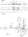
- the Figures 1 and 2 represent a bra strap that can be assembled by a device and according to a method of the present invention.
- This ramp comprises a main segment of ramp 1 and a segment 2.
- the secondary segment of strap 2 has a fixed length, and is formed of a length of tape 3 closed in a fastening loop 4 on a connecting ring 5.
- the main segment of ramp 1 has a variable length its length can be modified by sliding a ruler 6 along a section of ribbon 7.
- the rule 6, as illustrated in the figures, is a double ring 8 flattened, defining a first slot 8 and a second slot 9, both oriented transversely, and separated from each other by a central cross member 10.
- a first end 11 of the tape 7 is looped integrally on itself around the central web 10, then the tape 7 is formed according to a control loop 12 passing in the connecting ring 5.
- the ribbon 7 then passes into the second slot 9 and into the first slot 8 to exit in an upstream section 13.
- a transfer clamp 20, an insertion finger 21, a sonotrode 22, a welding anvil 23, a retractable anvil support 24, a cutting anvil 25, a stretching finger 26, means of rotation are thus distinguished.
- guide comprising a telescopic guide 27 associated with the transfer clamp 20, and a clamping shoe 28.
- first support means 29 capable of holding the rule 6 in appropriate positions for the various steps of the method.
- a direction of longitudinal progression is defined, illustrated by the arrow 30, or direction in which the ribbon 7 is unwound from a reserve ribbon not illustrated on these Figures 3 to 34 .
- the ribbon 7 is brought in a substantially horizontal plane, the insertion finger 21 and the sonotrode 22 being disposed above the general progression plane of the ribbon 7, while the anvil 23, the cutting anvil 25, the retractable anvil support 24 and the first support means 29 are arranged below the general plane of progression of the ribbon 7.
- the first support means 29 comprise a first cross member 29a and a second cross member 29b, generally perpendicular to the direction of progression 30, and between which the rule 6 engages and is held.
- the first crosspiece 29a has an upper face which constitutes the welding anvil 23, adapted to cooperate with the sonotrode 22.
- the first support means 29 are fixed in longitudinal position in the direction of progression 30, but are pivotally mounted about a transverse axis collinear with the crossbar 10. It will be considered that the first support means 29 can pivot around the cross member 10, according to an amplitude of 360 °.
- the insertion finger 21, the clamping shoe 28 and the sonotrode 22 are mounted on a common support 31, schematically illustrated in dashed lines, which is itself displaceable in the direction of progression between three positions: in a first position, illustrated on the figure 3 , the insertion finger 21 is facing the downstream slot of the rule 6 (the first slot 8 in the case of the figure 3 ); in a second position, illustrated on the figure 12 , the sonotrode 22 is facing the upstream cross member of the first support means 29 (the first crossbar 29a anvil 23 on the figure 12 ), the insertion finger 21 being offset downstream in the direction of progression 30; in a third position, illustrated on the figure 17 , the insertion finger 21 is facing the upstream slot of the rule 6 (the second slot 9 in the case of the figure 17 ).
- the transfer clip 20 can take two states, namely a relaxed state illustrated on the figure 3 , in which it releases the ribbon 7 for its progression in the direction of progression 30, and a tight state illustrated on the figure 4 in which it is in rubbing contact with the ribbon 7.
- the transfer tong 20 is movable longitudinally along the advancing direction 30, between a retracted position illustrated in FIG. figure 3 in which it is upstream and away from the first support means 29, and a close position illustrated on the figure 4 in which it is moved to the vicinity of the first support means 29 while remaining upstream of said first support means 29.
- the telescopic guide 27 is associated with the transfer clip 20, that is to say that it moves in longitudinal movement with the transfer clip 20 during its movements between the retracted position ( figure 3 ) and the close position ( figure 4 ).
- the telescopic guide 27 can be selectively deployed and retracted longitudinally vis-à-vis the transfer clamp 20, which can take an extended position illustrated on the figures 3 and 4 for example, then an intermediate position illustrated on the figures 5 and 6 for example, and finally a retracted position illustrated on the figures 11 and 12 for example.
- the telescopic guide 27 When the transfer clamp 20 is in the retracted position, the telescopic guide 27 is in all cases upstream of the first support means 29.
- the telescopic guide 27 When the transfer clamp 20 is in the close position, the telescopic guide 27 has its downstream end 27a located with regard to the downstream cross member of the first support means 29 (the cross member 29b on the figure 4 for example), its downstream end 27a facing the upstream cross member of the first support means 29 (the cross member 29a on the figure 5 for example) when in the intermediate position, and its downstream end 27a is still upstream of the first support means 29 when in the retracted position as illustrated on the figure 11 .
- the retractable anvil support 24 is for example a pivotally mounted piece about a transverse lower axis 24a, between a retracted position illustrated on the figure 3 in which it is away from the upstream cross member 29a, and a support position as illustrated on the figure 14 in which it bears against the underside of the upstream cross member 29a.
- the clamping shoe 28, mounted on the common support 31, is movable vertically between a retracted position, illustrated in FIG. figure 3 , in which it is away from the first support means 29, and a clamping position, illustrated for example on the figures 23 and 24 , in which he is close to the first support means 29 bearing on the upper face of the ring 5 to tighten the ribbon 7 against the ring 5.
- the telescopic guide 27 is designed as a gutter to support a ribbon end portion and to guide it laterally from the transfer clip 20 to its downstream end 27a, while being able to slide along the ribbon 7 in the direction of the ribbon. progression 30.
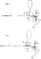
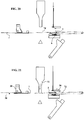
- the transfer clamp 20 is released and in the retracted position, the telescopic guide 27 is deployed, the sonotrode 22, the insertion finger 21 and the clamping shoe 28 are retracted, the common support 31 is in the first position, the anvil support 24 is retracted, the cutting anvil 25 is retracted, and the first support means 29 hold a ruler 6 in a horizontal position, with the first crossbar 29a upstream of the ruler 6, and with the second crossbar 29b downstream of the rule 6.
- the ribbon 7 extends to the downstream end 27a of the telescopic guide 27, its free end 7a may protrude slightly downstream. The first step a) of the method is thus carried out.
- step b) is carried out to transfer the ribbon.
- the transfer clamp 20 is lowered to the tightened state to engage the ribbon 7, then the transfer clamp 20, the telescopic guide 27 and the ribbon 7 are moved downstream until the transfer clamp 20 reaches its close position.
- the downstream end portion 7b of the ribbon 7 is thus guided by the telescopic guide 27 forming guide means, downstream of the transfer clip 20, and is pushed downstream by the transfer clip 20
- the free end 7a of the ribbon 7, held in the downstream end 27a of the telescopic guide 27, is then located at the right of the second crossmember 29b of the first support means 29, the ribbon 7 having a section d the downstream end 7b deployed above and parallel to the assembly formed by the first support means 29 and the rule 6.
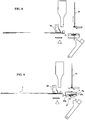
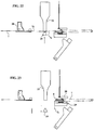
- the telescopic guide 27 is retracted to the intermediate position, its downstream end 27a being at the right of the first cross member 29a of the first support means 29, the transfer clamp 20 always being in a tight state to oppose the simultaneous withdrawal ribbon 7 with the telescopic guide 27.
- the tape 7 is thus held by the telescopic guide 27 near the rule 6 for the next operation, and the downstream end portion 7b of the ribbon 7 remains on the first support means 29 and rule 6.
- step c) of first penetration by the insertion finger 21 is illustrated: the insertion finger 21 is lowered until it passes through the first slot 8 of the rule 6, driving with it the downstream end portion 7b of the ribbon 7 which then hangs down.
- step d) of the method during which the insertion finger 21 is retracted into its retracted position, and the ruler 6 is rotated by 180 degrees in a first direction of rotation 32 around its central cross member 10, so as to go up while moving downstream the downstream end portion 7b of the ribbon 7.
- the downstream end portion 7b of the ribbon 7 is then found above the crossbar 29a, which she -Even is downstream of the rule 6, while the crossbar 29b is found upstream of the rule 6.
- the second transverse slot 9 of the rule 6 is in front of the insertion finger 21.
- the transfer clamp 20 is always lowered on the ribbon 7 to block it.
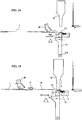
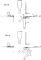
- step e) of the method in which the downstream end portion 7b is introduced into the second slot 9 of the rule 6, is illustrated by means of the insertion finger 21 which is lowered and which traverses the second slot 9.
- the transfer clip 20 always blocks the strip 7 upstream of the rule 6.
- step f) of the method during which the insertion finger 21 is withdrawn to its retracted position, the rule 6 is returned by pivoting the first support means 29 in the second direction 33 of rotation around the central cross member 10, and at the same time the common support 31 is moved downstream to bring the sonotrode 22 facing the welding anvil 23 which is again upstream of the rule 6.
- the transfer clip 20 the free end 7a of the ribbon 7 is engaged between the upstream ply 7d and the welding anvil 23.
- the first support means 29 provide a function of means for centering the free end 7a of the ribbon 7 7, guiding it perfectly to engage it against the upstream segment 7d of ribbon without risk of lateral overshoot and formation of a lateral protrusion 11a ( figure 2 ).
- the tilting anvil support 24 is tilted to bear under the upstream beam 29a comprising the welding anvil 23.
- step g the sonotrode 22 is lowered by activating it, and the transfer clip 20 and the telescopic guide 27 associated with it are moved upstream, away from the rule 6.
- the sonotrode 22 then ensures the welding of the downstream end section portion 7b of the ribbon 7 adjacent to the free end 7a on the upstream ply 7d which is juxtaposed between the sonotrode 22 and the welding anvil 23.
- step h in which the sonotrode 22 is withdrawn to its retracted position, and the transverse stretching finger 26 is moved downstream beyond the first support means 29, the stretching finger 26 being engaged on an intermediate portion 7c of the ribbon 7 and engaged between the rule 6 and the upstream ply 7d of the ribbon 7.
- the transfer clip 20 remains loose, allowing the unwinding of a necessary length of the tape 7 to make the adjustment loop 12 by following the displacement of the transverse stretching finger 26. It is understood that the displacement of the transverse stretching finger 26 determines the length of the adjustment loop 12.
- the figure 17 illustrates a next step during which the common support 31 is moved upstream to the third position in which the insertion finger 21 is facing the second slot 9 of the rule 6.
- the transfer clamp 20 is tightened to lock the ribbon 7 upstream of the first support means 29.
- step i) of the method is carried out by moving the ring 5 to bring it above the rule 6 between the rule 6 and the upstream upper ply 7d of the ribbon 7.
- the clamping shoe 28 is lowered to clamp a section of the upper web 7d of ribbon 7 between the clamping shoe 28 and the ring 5, and the sonotrode 22 is lowered, while keeping the transfer clamp 20 in a longitudinal position fixed along the direction of progression 30.
- step j) is illustrated, during which, while holding the transfer clamp 20 tight, the upper web 7d of ribbon 7 is cut by feeding the sonotrode 22 and applying the cutting anvil 25. , realizing an upstream end portion 7e ribbon.
- step k) of the method is carried out by lowering the insertion finger 21 so that it simultaneously passes through the ring 5 and the second slot 9 of the rule 6, simultaneously driving the upstream end portion 7e of the ribbon 7 which then passes through the ring 5 and the rule 6.
- the insertion finger 21 is removed, and on the figure 27 the insertion finger 21 and the clamping shoe 28 are moved towards their retracted position away from the ring 5, and the retractable anvil support 24 is tilted towards its support position, which anvil support 24 then pushes upstream the upstream end portion 7e of the ribbon 7 and keeps it tight under the crossbar 29a.
- step m) of the method is carried out, during which the first support means 29 are pivoted by 180 degrees around the cross member 10, in the second direction of rotation 33 illustrated by the arrows.
- the first support means 29 guide the upstream end portion 7e ribbon, which straddles above the crossbar 29b which itself is upstream of the rule 6.
- the first slot 8 of the rule 6 is then found facing the insertion finger 21, which is still in its third longitudinal position.
- step n) of the method is carried out by lowering the insertion finger 21 which then passes through the first slot 8 of the rule 6 and carries with it the upstream end section 7e of the ribbon. Simultaneously, the stretching finger 26 can be brought upstream to an intermediate position to relax the adjustment loop 12.
- the clamping shoe 28 is retracted.
- the main strap segment 1 is then entirely constituted and can be removed from the device.
- the figure 35 illustrates the essential means of a device for implementing the method illustrated above in connection with the Figures 3 to 34 .
- a frame 100 which may comprise a ribbon supply, a reserve of loops, a reserve of rules, and means for holding and placing the various active elements of the device.
- the transfer clamp 20 is tightened or loosened by a jack 20a.
- the telescopic guide 27 is moved longitudinally, relative to the transfer clamp 20, by the actuation of a longitudinal cylinder 27b.
- the assembly constituted by the transfer clamp 20 and the telescopic guide 27 is moved longitudinally with respect to the frame 100 by the actuation of a longitudinal jack 34.
- the first support means 29 are urged in rotation by rotation means such that a motor 29c carried by the frame 100.
- the common support 31 is moved longitudinally by a jack 31a. On the common support 31, the assembly formed by the sonotrode 22, the clamping shoe 28 and the insertion finger 21 is moved vertically by a jack 22a.
- the insertion finger 21 is moved vertically by a jack 21a.
- the cutting anvil 25 is moved vertically by a jack 25a.
- the retractable anvil support 24 is pivoted by the actuation of a jack 24b.
- the ring 5 is held by a ring support 35 displaceable by displacement and holding means 135 able to move the ring support 35 and the ring 5 between an upstream retracted position ( Figures 1 to 18 ), an upstream upward position ( figure 19 ), a commitment position ( Figures 20 to 27 ) facing the first support means 29, and a downstream position ( Figures 28 to 34 ).
- the displacement and holding means 135 are able to hold the ring support 35 and the ring 5 in the fixed position of engagement with the first support means 29 to allow simultaneous engagement of the strip 7 in the ring 5 and in rule 6 ( figure 25 ) by the single finger of introduction 21.
- the stretching finger 26 is displaced by drive means 26a in longitudinal translation in the direction of progression 30.
Landscapes
- Engineering & Computer Science (AREA)
- Textile Engineering (AREA)
- Impression-Transfer Materials And Handling Thereof (AREA)
- Absorbent Articles And Supports Therefor (AREA)
- Purses, Travelling Bags, Baskets, Or Suitcases (AREA)
Claims (10)
- Verfahren zur Montage eines Hauptabschnittes (1) eines Trägerbandes mit Schnalle, umfassend die folgenden Schritte:a) Halten einer Verstellschnalle (6) mit zwei Fenstern (8, 9) in einer festen Ausgangsposition, in der ein erstes Fenster (8) quer und bezüglich der Arbeitsrichtung (30) nach vorn weist, während ein zweites Fenster (9) quer und bezüglich der Arbeitsrichtung (30) nach hinten ausgerichtet ist,b) Erfassen eines Zwischenabschnittes eines Bandes (7) mittels einer beweglichen Vorschubkluppe (20) hinter der Schnalle (6) und Verschieben des Bandes (7) mittels der Vorschubkluppe (20) nach vorn, um den voreilenden Endabschnitt (7b) des Bandes gegenüber der Schnalle (6) und parallel zu dieser vorzuschieben, bis das freie Ende (7a) des Bandes vor der Schnalle (6) liegt,c) Einführen des vorderen Endabschnittes (7b) des Bandes (7) in das erste Fenster (8) der Schnalle (6), durch Schubkraft mittels eines Einführfingers (21),d) Zurückziehen des Einführfingers (21) und Schwenken der Schnalle (6) um 180° in einer ersten Drehrichtung (32) um den Mittelsteg (10) der Schnalle (6), um den voreilenden Endabschnitt (7b) des Bandes (7) vor die Schnalle (6) zu führen,e) Einführen des vorderen Endabschnittes (7b) des Bandes (7) in das zweite Fenster (9) der Schnalle (6) durch Schubkraft mittels des Einführfingers (21),f) Zurückziehen des Einführfingers (21) und Schwenken der Schnalle (6) um ihren Mittelsteg (10) in der zweiten Drehrichtung (33) um 180°, so dass das freie Ende (7a) des Bandes (7) an dem nacheilenden Bandabschnitt (7d) hinter der Schnalle (6) anliegt,g) Verbinden des freien Endes (7a) des Bandes (7) mit dem hinteren Bandabschnitt (7d),h) Abziehen einer Bandlänge nach vorn mittels eines quer angeordneten Zugfingers (26), der einen Zwischenabschnitt (7c) des Bandes zwischen der Schnalle (6) und dem hinteren Bandabschnitt (7d) erfasst,i) Einführen eines Verbindungsringes (5) parallel zwischen die Schnalle (6) und den hinteren Bandabschnitt (7d) und Festhalten gegenüber der Schnalle (6),j) Durchtrennen des Bandes (7) hinter der Schnalle (6), wodurch ein hinterer Endabschnitt (7e) des Bandes gebildet wird,k) Einführen des hinteren Endabschnittes (7e) des Bandes in den Verbindungsring (5) und in das zweite Fenster (9) der Schnalle (6) mittels des Einführfingers (21),l) Zurückziehen des Einführfingers (21), Blockieren des hinteren Endabschnittes (7e) des Bandes und Vorschieben des Ringes (5) durch eine Gleitbewegung auf dem Band (7),m) Schwenken der Schnalle (6) um ihren Mittelsteg (10) in der zweiten Drehrichtung (33) um 180°,n) Einführen des hinteren Endabschnittes (7e) des Bandes in das erste Fenster (8) der Schnalle (6) mittels des Einführfingers (21) und Freigabe des auf diese Weise erzeugten Hauptabschnittes (1) des Trägerbandes.
- Verfahren nach Anspruch 1, dadurch gekennzeichnet, dass bei allen Verfahrensschritten die Vorschubkluppe (20) das Band (7) hinter der Schnalle (6) hält und dass während des Verfahrensschrittes b) der voreilende Endabschnitt (7b) des Bandes (7) durch Überführungsmittel (27) vor der Vorschubkluppe (20) geführt und durch diese nach vorn geschoben wird.
- Verfahren nach Anspruch 1 oder 2, dadurch gekennzeichnet, dass während des Schrittes f) die Vorschubkluppe (20) den nacheilenden Bandabschnitt (7d) nahe bei der Schnalle (6) festhält und dass Zentriermittel (29) das freie Ende (7a) des Bandes so führen, dass es zur Anlage an dem nacheilenden Bandabschnitt (7d) kommt.
- Verfahren nach einem der Ansprüche 1 bis 3, dadurch gekennzeichnet, dass in dem Verfahrensschritt g) das freie Ende (7a) des Bandes (7) mit dem hinteren Bandabschnitt (7d) durch Ultraschall zwischen einer Sonotrode (22) und einer Schweißbacke (23) verschweißt wird.
- Verfahren nach einem der Ansprüche 1 bis 4, dadurch gekennzeichnet, dass im Verfahrensschritt j) das Band (7) zwischen der Sonotrode (22) und einer Schneidbacke (25) über eine in Querrichtung verlaufende Schnittlinie durchtrennt wird.
- Vorrichtung zur Durchführung des Verfahrens nach einem der Ansprüche 1 bis 5, umfassend ein Gestell (100), einen Bandvorrat, einen Vorrat von Halteschlaufen, einen Vorrat von Verstellschnallen, erste Tragmittel (29) zum Halten einer Schnalle (6) in der Ausgangsposition, zweite Tragmittel (35) zum Halten eines Verbindungsringes (5), einen Einführfinger (21) mit seinen Betätigungsmitteln (21a), die ihn durch ein Fenster (8, 9) der Schnalle (6) schieben, Mittel zum Halten (20, 27, 29) des Bandes (7), Schneidmittel (22, 25) zum Durchtrennen des Bandes (7), Mittel (22, 23) zum Verbinden des Bandes (7) mit sich selbst, Schwenkmittel (29c) zum Drehen der ersten Tragmittel (29) um den Mittelsteg (10) der Schnalle (6), einen Zugfinger (26) mit seinen Betätigungsmitteln (26a) für die Längsverschiebung in Arbeitsrichtung (30), dadurch gekennzeichnet, dass:- die ersten Tragmittel (29) eine erste Traverse (29a) und eine zweite Traverse (29b) haben, die parallel zueinander ausgerichtet sind und zwischen die die Schnalle (6) eingreift und zwischen denen sie gehalten ist,- die erste Traverse (29a) eine Schweißbacke (23) bildet, die mit einer Sonotrode (22) in Wirkverbindung ist, um das Band (7) während des Verbindungsschrittes mit sich selbst zu vereinigen.
- Vorrichtung nach Anspruch 6, dadurch gekennzeichnet, dass die Mittel zum Halten des Bandes (7) umfassen:- eine Vorschubkluppe (20) sowie Mittel (34) für die Längsverschiebung der Vorschubkluppe (20) in Arbeitsrichtung (30) von hinten nach vorn, so dass diese immer hinter den ersten Tragmitteln (29) bleibt,- eine Teleskopführung (27), die mit der Vorschubkluppe (20) verbunden ist und dazu dient, den vorderen Endabschnitt (7b) des Bandes (7) über die ersten Tragmittel (29) hinaus nach vorn zu verschieben und sich hinter die ersten Tragmittel (29) zurückzuziehen.
- Vorrichtung nach Anspruch 6 oder 7, dadurch gekennzeichnet, dass- die ersten Tragmittel (29) eine in Arbeitsrichtung (30) feste Längsposition haben,- der Einführfinger (21) und die Sonotrode (22) auf einem gemeinsamen Träger (31) angebracht sind, der in Arbeitsrichtung (30) verschiebbar ist zwischen einer ersten Stellung, in der der Einführfinger (21) dem vorderen Fenster (8) der Schnalle (6) gegenüberliegt, einer zweiten Stellung, in der die Sonotrode (22) hinter der Schnalle (6) der ersten Traverse (29a) gegenüberliegt, und einer dritten Stellung, in der der Einführfinger (21) dem hinteren Fenster (9) der Schnalle (6) gegenüberliegt.
- Vorrichtung nach einem der Ansprüche 6 bis 8, dadurch gekennzeichnet, dass die zweiten Tragmittel (35) zum Halten eines Verbindungsrings (5) Mittel (135) zum Verstellen und Halten haben, die so ausgebildet sind, dass sie die zweiten Tragmittel (35) und den Verbindungsring (5) in einer festen Eingriffsstellung gegenüber den ersten Tragmitteln (29) halten, um für einen gleichzeitigen Eingriff des Bandes (7) in den Verbindungsring (5) und in die Schnalle (6) durch den Einführfinger (21) zu sorgen.
- Vorrichtung nach einem der Ansprüche 6 bis 9, dadurch gekennzeichnet, dass diese nur einen Einführfinger (21) aufweist.
Applications Claiming Priority (2)
| Application Number | Priority Date | Filing Date | Title |
|---|---|---|---|
| FR0850936A FR2927509B1 (fr) | 2008-02-14 | 2008-02-14 | Procede et dispositif pour le montage de bretelles a reglet |
| PCT/IB2009/050606 WO2009101601A2 (fr) | 2008-02-14 | 2009-02-13 | Procede et dispositif pour le montage de bretelles a reglet |
Publications (2)
| Publication Number | Publication Date |
|---|---|
| EP2242387A2 EP2242387A2 (de) | 2010-10-27 |
| EP2242387B1 true EP2242387B1 (de) | 2016-12-14 |
Family
ID=39885002
Family Applications (1)
| Application Number | Title | Priority Date | Filing Date |
|---|---|---|---|
| EP09710832.8A Active EP2242387B1 (de) | 2008-02-14 | 2009-02-13 | Verfahren und vorrichtung zur anordnung von trägern mit einem achter-ring |
Country Status (3)
| Country | Link |
|---|---|
| EP (1) | EP2242387B1 (de) |
| FR (1) | FR2927509B1 (de) |
| WO (1) | WO2009101601A2 (de) |
Family Cites Families (3)
| Publication number | Priority date | Publication date | Assignee | Title |
|---|---|---|---|---|
| FR2515009A1 (fr) * | 1981-10-23 | 1983-04-29 | Mecanique Ste Forezienne | Procede et moyens d'enfilage des boucles sur des bretelles, et notamment des bretelles de soutiens-gorge et autres sous-vetements et vetements |
| FR2631788B1 (fr) * | 1988-05-31 | 1990-09-07 | Atamec Crozet Fourneyron | Procede et dispositif pour fabriquer des bretelles pour sous-vetements feminins |
| FR2638069B1 (fr) * | 1988-10-21 | 1991-11-08 | Cera France | Procede et dispositif pour realiser une bretelle de vetement telle qu'une bretelle de soutien-gorge |
-
2008
- 2008-02-14 FR FR0850936A patent/FR2927509B1/fr not_active Expired - Fee Related
-
2009
- 2009-02-13 EP EP09710832.8A patent/EP2242387B1/de active Active
- 2009-02-13 WO PCT/IB2009/050606 patent/WO2009101601A2/fr not_active Ceased
Non-Patent Citations (1)
| Title |
|---|
| None * |
Also Published As
| Publication number | Publication date |
|---|---|
| EP2242387A2 (de) | 2010-10-27 |
| FR2927509B1 (fr) | 2010-03-26 |
| WO2009101601A3 (fr) | 2009-10-08 |
| FR2927509A1 (fr) | 2009-08-21 |
| WO2009101601A2 (fr) | 2009-08-20 |
Similar Documents
| Publication | Publication Date | Title |
|---|---|---|
| EP0419299A2 (de) | Wagen zum Abwickeln von einem Film zu einer Verpackungsmaschine | |
| EP0875476A1 (de) | Wickler mit zwei Spindeln zum Aufwickeln einer Bahn | |
| FR2491527A1 (fr) | Machine portative pour realiser automatiquement les ligatures sur des armatures de beton arme, et procede de fonctionnement | |
| EP2242387B1 (de) | Verfahren und vorrichtung zur anordnung von trägern mit einem achter-ring | |
| CA2790180C (fr) | Procede d'exploitation d'une machine de tressage de fibres renforcantes | |
| CA1253528A (fr) | Procede et dispositif de prehension de couches souples en particulier textiles et machine pour la prehension et le transfert desdites couches | |
| FR2573030A1 (fr) | Procede et machine d'emballage d'une charge dans un troncon de gaine en un materiau souple | |
| FR2565892A1 (fr) | Appareil pour l'application automatique sous pression de bandes de caoutchouc ou matiere de revetement similaire sur des surfaces etendues de parois | |
| EP2629960B1 (de) | Vorrichtung zum dehnen einer folie aus synthetischem material in querrichtung und zur gesteuerten relaxation in längsrichtung | |
| FR2878241A1 (fr) | Machine automatique pour la formation d'un noeud a l'aide d'une ficelle en extremite d'une gaine tubulaire en vue de l'obturer par constriction sous l'effet du serrage du noeud | |
| EP4159656B1 (de) | System zur befestigung des freien endes eines spulenfadens | |
| FR2761864A1 (fr) | Procede et dispositif servant a former des espaces vides dans une chaine de fermeture a glissiere | |
| EP2730527B1 (de) | Abwickelvorrichtung mit einer Bandanhebevorrichtung | |
| EP2671698B1 (de) | Werkbank zur Herstellung von Balken durch Fließpressen | |
| EP0945351A1 (de) | Werkzeug zum Entfernen eines Umreifungsbandes | |
| EP0369898A1 (de) | Verfahren und Vorrichtung zur Herstellung von Schulterträgern für Bekleidung, insbesondere von Schulterträgern für Büstenhalter | |
| EP4433639B1 (de) | Verfahren zum schneiden eines dreidimensionalen gewebes mit zwei durch streben miteinander verbundenen stoffbahnen | |
| FR2723361A1 (fr) | Dispositif de coupe et d'application, sans colle, du debut de bande d'une nouvelle bobine sur un mandrin d'un enrouleur | |
| EP0292490B1 (de) | Verfahren und vorrichtung zum greifen eines biegsamen gegenstandes auf einem stapel | |
| FR2583438A1 (fr) | Procede de placement de pieces de tissu sur une zone precedant la zone de decoupe d'une machine de decoupe, et dispositif semi-automatique pour la mise en oeuvre de ce procede | |
| FR2464108A1 (fr) | Procede et appareil pour detacher une bande d'une bobine de tole metallique enroulee | |
| FR2503593A1 (fr) | Dispositif de bobinages supplementaires dans une installation de refendage de toles | |
| EP0211749A1 (de) | Verfahren und Vorrichtung zur Herstellung eines Gegenstandes, der eine flache Spirale aus Metalldraht enthält | |
| FR2709200A1 (fr) | Appareil pour ligaturer une anche de hautbois ou cor anglais. | |
| BE571321A (de) |
Legal Events
| Date | Code | Title | Description |
|---|---|---|---|
| PUAI | Public reference made under article 153(3) epc to a published international application that has entered the european phase |
Free format text: ORIGINAL CODE: 0009012 |
|
| 17P | Request for examination filed |
Effective date: 20100803 |
|
| AK | Designated contracting states |
Kind code of ref document: A2 Designated state(s): AT BE BG CH CY CZ DE DK EE ES FI FR GB GR HR HU IE IS IT LI LT LU LV MC MK MT NL NO PL PT RO SE SI SK TR |
|
| AX | Request for extension of the european patent |
Extension state: AL BA RS |
|
| DAX | Request for extension of the european patent (deleted) | ||
| GRAP | Despatch of communication of intention to grant a patent |
Free format text: ORIGINAL CODE: EPIDOSNIGR1 |
|
| INTG | Intention to grant announced |
Effective date: 20160719 |
|
| GRAS | Grant fee paid |
Free format text: ORIGINAL CODE: EPIDOSNIGR3 |
|
| GRAA | (expected) grant |
Free format text: ORIGINAL CODE: 0009210 |
|
| AK | Designated contracting states |
Kind code of ref document: B1 Designated state(s): AT BE BG CH CY CZ DE DK EE ES FI FR GB GR HR HU IE IS IT LI LT LU LV MC MK MT NL NO PL PT RO SE SI SK TR |
|
| REG | Reference to a national code |
Ref country code: GB Ref legal event code: FG4D Free format text: NOT ENGLISH |
|
| REG | Reference to a national code |
Ref country code: CH Ref legal event code: EP |
|
| REG | Reference to a national code |
Ref country code: IE Ref legal event code: FG4D Free format text: LANGUAGE OF EP DOCUMENT: FRENCH |
|
| REG | Reference to a national code |
Ref country code: AT Ref legal event code: REF Ref document number: 852753 Country of ref document: AT Kind code of ref document: T Effective date: 20170115 |
|
| RAP2 | Party data changed (patent owner data changed or rights of a patent transferred) |
Owner name: CERA ENGINEERING |
|
| REG | Reference to a national code |
Ref country code: DE Ref legal event code: R096 Ref document number: 602009043039 Country of ref document: DE |
|
| REG | Reference to a national code |
Ref country code: FR Ref legal event code: PLFP Year of fee payment: 9 |
|
| PG25 | Lapsed in a contracting state [announced via postgrant information from national office to epo] |
Ref country code: LV Free format text: LAPSE BECAUSE OF FAILURE TO SUBMIT A TRANSLATION OF THE DESCRIPTION OR TO PAY THE FEE WITHIN THE PRESCRIBED TIME-LIMIT Effective date: 20161214 |
|
| REG | Reference to a national code |
Ref country code: LT Ref legal event code: MG4D |
|
| REG | Reference to a national code |
Ref country code: NL Ref legal event code: MP Effective date: 20161214 |
|
| PG25 | Lapsed in a contracting state [announced via postgrant information from national office to epo] |
Ref country code: GR Free format text: LAPSE BECAUSE OF FAILURE TO SUBMIT A TRANSLATION OF THE DESCRIPTION OR TO PAY THE FEE WITHIN THE PRESCRIBED TIME-LIMIT Effective date: 20170315 Ref country code: NO Free format text: LAPSE BECAUSE OF FAILURE TO SUBMIT A TRANSLATION OF THE DESCRIPTION OR TO PAY THE FEE WITHIN THE PRESCRIBED TIME-LIMIT Effective date: 20170314 Ref country code: SE Free format text: LAPSE BECAUSE OF FAILURE TO SUBMIT A TRANSLATION OF THE DESCRIPTION OR TO PAY THE FEE WITHIN THE PRESCRIBED TIME-LIMIT Effective date: 20161214 Ref country code: LT Free format text: LAPSE BECAUSE OF FAILURE TO SUBMIT A TRANSLATION OF THE DESCRIPTION OR TO PAY THE FEE WITHIN THE PRESCRIBED TIME-LIMIT Effective date: 20161214 |
|
| REG | Reference to a national code |
Ref country code: AT Ref legal event code: MK05 Ref document number: 852753 Country of ref document: AT Kind code of ref document: T Effective date: 20161214 |
|
| PG25 | Lapsed in a contracting state [announced via postgrant information from national office to epo] |
Ref country code: FI Free format text: LAPSE BECAUSE OF FAILURE TO SUBMIT A TRANSLATION OF THE DESCRIPTION OR TO PAY THE FEE WITHIN THE PRESCRIBED TIME-LIMIT Effective date: 20161214 Ref country code: HR Free format text: LAPSE BECAUSE OF FAILURE TO SUBMIT A TRANSLATION OF THE DESCRIPTION OR TO PAY THE FEE WITHIN THE PRESCRIBED TIME-LIMIT Effective date: 20161214 |
|
| PGFP | Annual fee paid to national office [announced via postgrant information from national office to epo] |
Ref country code: BE Payment date: 20170131 Year of fee payment: 9 |
|
| PG25 | Lapsed in a contracting state [announced via postgrant information from national office to epo] |
Ref country code: NL Free format text: LAPSE BECAUSE OF FAILURE TO SUBMIT A TRANSLATION OF THE DESCRIPTION OR TO PAY THE FEE WITHIN THE PRESCRIBED TIME-LIMIT Effective date: 20161214 |
|
| PG25 | Lapsed in a contracting state [announced via postgrant information from national office to epo] |
Ref country code: RO Free format text: LAPSE BECAUSE OF FAILURE TO SUBMIT A TRANSLATION OF THE DESCRIPTION OR TO PAY THE FEE WITHIN THE PRESCRIBED TIME-LIMIT Effective date: 20161214 Ref country code: IS Free format text: LAPSE BECAUSE OF FAILURE TO SUBMIT A TRANSLATION OF THE DESCRIPTION OR TO PAY THE FEE WITHIN THE PRESCRIBED TIME-LIMIT Effective date: 20170414 Ref country code: EE Free format text: LAPSE BECAUSE OF FAILURE TO SUBMIT A TRANSLATION OF THE DESCRIPTION OR TO PAY THE FEE WITHIN THE PRESCRIBED TIME-LIMIT Effective date: 20161214 Ref country code: CZ Free format text: LAPSE BECAUSE OF FAILURE TO SUBMIT A TRANSLATION OF THE DESCRIPTION OR TO PAY THE FEE WITHIN THE PRESCRIBED TIME-LIMIT Effective date: 20161214 Ref country code: SK Free format text: LAPSE BECAUSE OF FAILURE TO SUBMIT A TRANSLATION OF THE DESCRIPTION OR TO PAY THE FEE WITHIN THE PRESCRIBED TIME-LIMIT Effective date: 20161214 |
|
| PGFP | Annual fee paid to national office [announced via postgrant information from national office to epo] |
Ref country code: DE Payment date: 20170425 Year of fee payment: 9 |
|
| PG25 | Lapsed in a contracting state [announced via postgrant information from national office to epo] |
Ref country code: PT Free format text: LAPSE BECAUSE OF FAILURE TO SUBMIT A TRANSLATION OF THE DESCRIPTION OR TO PAY THE FEE WITHIN THE PRESCRIBED TIME-LIMIT Effective date: 20170414 Ref country code: BG Free format text: LAPSE BECAUSE OF FAILURE TO SUBMIT A TRANSLATION OF THE DESCRIPTION OR TO PAY THE FEE WITHIN THE PRESCRIBED TIME-LIMIT Effective date: 20170314 Ref country code: AT Free format text: LAPSE BECAUSE OF FAILURE TO SUBMIT A TRANSLATION OF THE DESCRIPTION OR TO PAY THE FEE WITHIN THE PRESCRIBED TIME-LIMIT Effective date: 20161214 Ref country code: PL Free format text: LAPSE BECAUSE OF FAILURE TO SUBMIT A TRANSLATION OF THE DESCRIPTION OR TO PAY THE FEE WITHIN THE PRESCRIBED TIME-LIMIT Effective date: 20161214 Ref country code: ES Free format text: LAPSE BECAUSE OF FAILURE TO SUBMIT A TRANSLATION OF THE DESCRIPTION OR TO PAY THE FEE WITHIN THE PRESCRIBED TIME-LIMIT Effective date: 20161214 |
|
| REG | Reference to a national code |
Ref country code: DE Ref legal event code: R097 Ref document number: 602009043039 Country of ref document: DE |
|
| PG25 | Lapsed in a contracting state [announced via postgrant information from national office to epo] |
Ref country code: MC Free format text: LAPSE BECAUSE OF FAILURE TO SUBMIT A TRANSLATION OF THE DESCRIPTION OR TO PAY THE FEE WITHIN THE PRESCRIBED TIME-LIMIT Effective date: 20161214 |
|
| REG | Reference to a national code |
Ref country code: CH Ref legal event code: PL |
|
| PLBE | No opposition filed within time limit |
Free format text: ORIGINAL CODE: 0009261 |
|
| STAA | Information on the status of an ep patent application or granted ep patent |
Free format text: STATUS: NO OPPOSITION FILED WITHIN TIME LIMIT |
|
| PG25 | Lapsed in a contracting state [announced via postgrant information from national office to epo] |
Ref country code: CH Free format text: LAPSE BECAUSE OF NON-PAYMENT OF DUE FEES Effective date: 20170228 Ref country code: LI Free format text: LAPSE BECAUSE OF NON-PAYMENT OF DUE FEES Effective date: 20170228 |
|
| 26N | No opposition filed |
Effective date: 20170915 |
|
| GBPC | Gb: european patent ceased through non-payment of renewal fee |
Effective date: 20170314 |
|
| REG | Reference to a national code |
Ref country code: IE Ref legal event code: MM4A |
|
| PG25 | Lapsed in a contracting state [announced via postgrant information from national office to epo] |
Ref country code: DK Free format text: LAPSE BECAUSE OF FAILURE TO SUBMIT A TRANSLATION OF THE DESCRIPTION OR TO PAY THE FEE WITHIN THE PRESCRIBED TIME-LIMIT Effective date: 20161214 |
|
| PG25 | Lapsed in a contracting state [announced via postgrant information from national office to epo] |
Ref country code: LU Free format text: LAPSE BECAUSE OF NON-PAYMENT OF DUE FEES Effective date: 20170213 |
|
| REG | Reference to a national code |
Ref country code: FR Ref legal event code: PLFP Year of fee payment: 10 |
|
| PG25 | Lapsed in a contracting state [announced via postgrant information from national office to epo] |
Ref country code: IE Free format text: LAPSE BECAUSE OF NON-PAYMENT OF DUE FEES Effective date: 20170213 Ref country code: GB Free format text: LAPSE BECAUSE OF NON-PAYMENT OF DUE FEES Effective date: 20170314 Ref country code: SI Free format text: LAPSE BECAUSE OF FAILURE TO SUBMIT A TRANSLATION OF THE DESCRIPTION OR TO PAY THE FEE WITHIN THE PRESCRIBED TIME-LIMIT Effective date: 20161214 |
|
| REG | Reference to a national code |
Ref country code: DE Ref legal event code: R119 Ref document number: 602009043039 Country of ref document: DE |
|
| PG25 | Lapsed in a contracting state [announced via postgrant information from national office to epo] |
Ref country code: MT Free format text: LAPSE BECAUSE OF FAILURE TO SUBMIT A TRANSLATION OF THE DESCRIPTION OR TO PAY THE FEE WITHIN THE PRESCRIBED TIME-LIMIT Effective date: 20161214 |
|
| REG | Reference to a national code |
Ref country code: BE Ref legal event code: MM Effective date: 20180228 |
|
| PG25 | Lapsed in a contracting state [announced via postgrant information from national office to epo] |
Ref country code: DE Free format text: LAPSE BECAUSE OF NON-PAYMENT OF DUE FEES Effective date: 20180901 |
|
| PG25 | Lapsed in a contracting state [announced via postgrant information from national office to epo] |
Ref country code: BE Free format text: LAPSE BECAUSE OF NON-PAYMENT OF DUE FEES Effective date: 20180228 |
|
| PG25 | Lapsed in a contracting state [announced via postgrant information from national office to epo] |
Ref country code: HU Free format text: LAPSE BECAUSE OF FAILURE TO SUBMIT A TRANSLATION OF THE DESCRIPTION OR TO PAY THE FEE WITHIN THE PRESCRIBED TIME-LIMIT; INVALID AB INITIO Effective date: 20090213 |
|
| PG25 | Lapsed in a contracting state [announced via postgrant information from national office to epo] |
Ref country code: CY Free format text: LAPSE BECAUSE OF NON-PAYMENT OF DUE FEES Effective date: 20161214 |
|
| PG25 | Lapsed in a contracting state [announced via postgrant information from national office to epo] |
Ref country code: MK Free format text: LAPSE BECAUSE OF FAILURE TO SUBMIT A TRANSLATION OF THE DESCRIPTION OR TO PAY THE FEE WITHIN THE PRESCRIBED TIME-LIMIT Effective date: 20161214 |
|
| P01 | Opt-out of the competence of the unified patent court (upc) registered |
Effective date: 20230525 |
|
| PGFP | Annual fee paid to national office [announced via postgrant information from national office to epo] |
Ref country code: IT Payment date: 20260210 Year of fee payment: 18 |
|
| PGFP | Annual fee paid to national office [announced via postgrant information from national office to epo] |
Ref country code: FR Payment date: 20260106 Year of fee payment: 18 |
|
| PGFP | Annual fee paid to national office [announced via postgrant information from national office to epo] |
Ref country code: TR Payment date: 20260211 Year of fee payment: 18 |