EP2242570B1 - Verfahren zur thermokatalytischen depolymerisation von kunststoffmaterial - Google Patents
Verfahren zur thermokatalytischen depolymerisation von kunststoffmaterial Download PDFInfo
- Publication number
- EP2242570B1 EP2242570B1 EP07866775.5A EP07866775A EP2242570B1 EP 2242570 B1 EP2242570 B1 EP 2242570B1 EP 07866775 A EP07866775 A EP 07866775A EP 2242570 B1 EP2242570 B1 EP 2242570B1
- Authority
- EP
- European Patent Office
- Prior art keywords
- plastic material
- during
- heating
- depolymerisation
- reactor
- Prior art date
- Legal status (The legal status is an assumption and is not a legal conclusion. Google has not performed a legal analysis and makes no representation as to the accuracy of the status listed.)
- Active
Links
Images


Classifications
-
- B—PERFORMING OPERATIONS; TRANSPORTING
- B01—PHYSICAL OR CHEMICAL PROCESSES OR APPARATUS IN GENERAL
- B01J—CHEMICAL OR PHYSICAL PROCESSES, e.g. CATALYSIS OR COLLOID CHEMISTRY; THEIR RELEVANT APPARATUS
- B01J19/00—Chemical, physical or physico-chemical processes in general; Their relevant apparatus
- B01J19/18—Stationary reactors having moving elements inside
-
- B—PERFORMING OPERATIONS; TRANSPORTING
- B01—PHYSICAL OR CHEMICAL PROCESSES OR APPARATUS IN GENERAL
- B01F—MIXING, e.g. DISSOLVING, EMULSIFYING OR DISPERSING
- B01F27/00—Mixers with rotary stirring devices in fixed receptacles; Kneaders
- B01F27/05—Stirrers
- B01F27/11—Stirrers characterised by the configuration of the stirrers
- B01F27/112—Stirrers characterised by the configuration of the stirrers with arms, paddles, vanes or blades
- B01F27/1123—Stirrers characterised by the configuration of the stirrers with arms, paddles, vanes or blades sickle-shaped, i.e. curved in at least one direction
-
- B—PERFORMING OPERATIONS; TRANSPORTING
- B01—PHYSICAL OR CHEMICAL PROCESSES OR APPARATUS IN GENERAL
- B01F—MIXING, e.g. DISSOLVING, EMULSIFYING OR DISPERSING
- B01F27/00—Mixers with rotary stirring devices in fixed receptacles; Kneaders
- B01F27/05—Stirrers
- B01F27/11—Stirrers characterised by the configuration of the stirrers
- B01F27/113—Propeller-shaped stirrers for producing an axial flow, e.g. shaped like a ship or aircraft propeller
-
- B—PERFORMING OPERATIONS; TRANSPORTING
- B01—PHYSICAL OR CHEMICAL PROCESSES OR APPARATUS IN GENERAL
- B01F—MIXING, e.g. DISSOLVING, EMULSIFYING OR DISPERSING
- B01F27/00—Mixers with rotary stirring devices in fixed receptacles; Kneaders
- B01F27/05—Stirrers
- B01F27/11—Stirrers characterised by the configuration of the stirrers
- B01F27/114—Helically shaped stirrers, i.e. stirrers comprising a helically shaped band or helically shaped band sections
- B01F27/1142—Helically shaped stirrers, i.e. stirrers comprising a helically shaped band or helically shaped band sections of the corkscrew type
-
- B—PERFORMING OPERATIONS; TRANSPORTING
- B01—PHYSICAL OR CHEMICAL PROCESSES OR APPARATUS IN GENERAL
- B01F—MIXING, e.g. DISSOLVING, EMULSIFYING OR DISPERSING
- B01F27/00—Mixers with rotary stirring devices in fixed receptacles; Kneaders
- B01F27/05—Stirrers
- B01F27/11—Stirrers characterised by the configuration of the stirrers
- B01F27/114—Helically shaped stirrers, i.e. stirrers comprising a helically shaped band or helically shaped band sections
- B01F27/1145—Helically shaped stirrers, i.e. stirrers comprising a helically shaped band or helically shaped band sections ribbon shaped with an open space between the helical ribbon flight and the rotating axis
-
- B—PERFORMING OPERATIONS; TRANSPORTING
- B01—PHYSICAL OR CHEMICAL PROCESSES OR APPARATUS IN GENERAL
- B01F—MIXING, e.g. DISSOLVING, EMULSIFYING OR DISPERSING
- B01F27/00—Mixers with rotary stirring devices in fixed receptacles; Kneaders
- B01F27/80—Mixers with rotary stirring devices in fixed receptacles; Kneaders with stirrers rotating about a substantially vertical axis
-
- B—PERFORMING OPERATIONS; TRANSPORTING
- B01—PHYSICAL OR CHEMICAL PROCESSES OR APPARATUS IN GENERAL
- B01F—MIXING, e.g. DISSOLVING, EMULSIFYING OR DISPERSING
- B01F35/00—Accessories for mixers; Auxiliary operations or auxiliary devices; Parts or details of general application
- B01F35/90—Heating or cooling systems
- B01F35/92—Heating or cooling systems for heating the outside of the receptacle, e.g. heated jackets or burners
-
- B—PERFORMING OPERATIONS; TRANSPORTING
- B01—PHYSICAL OR CHEMICAL PROCESSES OR APPARATUS IN GENERAL
- B01F—MIXING, e.g. DISSOLVING, EMULSIFYING OR DISPERSING
- B01F35/00—Accessories for mixers; Auxiliary operations or auxiliary devices; Parts or details of general application
- B01F35/90—Heating or cooling systems
- B01F35/95—Heating or cooling systems using heated or cooled stirrers
-
- B—PERFORMING OPERATIONS; TRANSPORTING
- B01—PHYSICAL OR CHEMICAL PROCESSES OR APPARATUS IN GENERAL
- B01J—CHEMICAL OR PHYSICAL PROCESSES, e.g. CATALYSIS OR COLLOID CHEMISTRY; THEIR RELEVANT APPARATUS
- B01J19/00—Chemical, physical or physico-chemical processes in general; Their relevant apparatus
- B01J19/0053—Details of the reactor
- B01J19/0066—Stirrers
-
- B—PERFORMING OPERATIONS; TRANSPORTING
- B01—PHYSICAL OR CHEMICAL PROCESSES OR APPARATUS IN GENERAL
- B01J—CHEMICAL OR PHYSICAL PROCESSES, e.g. CATALYSIS OR COLLOID CHEMISTRY; THEIR RELEVANT APPARATUS
- B01J19/00—Chemical, physical or physico-chemical processes in general; Their relevant apparatus
- B01J19/008—Processes for carrying out reactions under cavitation conditions
-
- B—PERFORMING OPERATIONS; TRANSPORTING
- B01—PHYSICAL OR CHEMICAL PROCESSES OR APPARATUS IN GENERAL
- B01J—CHEMICAL OR PHYSICAL PROCESSES, e.g. CATALYSIS OR COLLOID CHEMISTRY; THEIR RELEVANT APPARATUS
- B01J19/00—Chemical, physical or physico-chemical processes in general; Their relevant apparatus
- B01J19/18—Stationary reactors having moving elements inside
- B01J19/20—Stationary reactors having moving elements inside in the form of helices, e.g. screw reactors
-
- B—PERFORMING OPERATIONS; TRANSPORTING
- B01—PHYSICAL OR CHEMICAL PROCESSES OR APPARATUS IN GENERAL
- B01J—CHEMICAL OR PHYSICAL PROCESSES, e.g. CATALYSIS OR COLLOID CHEMISTRY; THEIR RELEVANT APPARATUS
- B01J4/00—Feed or outlet devices; Feed or outlet control devices
- B01J4/001—Feed or outlet devices as such, e.g. feeding tubes
-
- B—PERFORMING OPERATIONS; TRANSPORTING
- B29—WORKING OF PLASTICS; WORKING OF SUBSTANCES IN A PLASTIC STATE IN GENERAL
- B29B—PREPARATION OR PRETREATMENT OF THE MATERIAL TO BE SHAPED; MAKING GRANULES OR PREFORMS; RECOVERY OF PLASTICS OR OTHER CONSTITUENTS OF WASTE MATERIAL CONTAINING PLASTICS
- B29B7/00—Mixing; Kneading
- B29B7/02—Mixing; Kneading non-continuous, with mechanical mixing or kneading devices, i.e. batch type
- B29B7/06—Mixing; Kneading non-continuous, with mechanical mixing or kneading devices, i.e. batch type with movable mixing or kneading devices
- B29B7/10—Mixing; Kneading non-continuous, with mechanical mixing or kneading devices, i.e. batch type with movable mixing or kneading devices rotary
- B29B7/12—Mixing; Kneading non-continuous, with mechanical mixing or kneading devices, i.e. batch type with movable mixing or kneading devices rotary with single shaft
- B29B7/14—Mixing; Kneading non-continuous, with mechanical mixing or kneading devices, i.e. batch type with movable mixing or kneading devices rotary with single shaft with screw or helix
-
- B—PERFORMING OPERATIONS; TRANSPORTING
- B29—WORKING OF PLASTICS; WORKING OF SUBSTANCES IN A PLASTIC STATE IN GENERAL
- B29B—PREPARATION OR PRETREATMENT OF THE MATERIAL TO BE SHAPED; MAKING GRANULES OR PREFORMS; RECOVERY OF PLASTICS OR OTHER CONSTITUENTS OF WASTE MATERIAL CONTAINING PLASTICS
- B29B7/00—Mixing; Kneading
- B29B7/02—Mixing; Kneading non-continuous, with mechanical mixing or kneading devices, i.e. batch type
- B29B7/06—Mixing; Kneading non-continuous, with mechanical mixing or kneading devices, i.e. batch type with movable mixing or kneading devices
- B29B7/10—Mixing; Kneading non-continuous, with mechanical mixing or kneading devices, i.e. batch type with movable mixing or kneading devices rotary
- B29B7/12—Mixing; Kneading non-continuous, with mechanical mixing or kneading devices, i.e. batch type with movable mixing or kneading devices rotary with single shaft
- B29B7/16—Mixing; Kneading non-continuous, with mechanical mixing or kneading devices, i.e. batch type with movable mixing or kneading devices rotary with single shaft with paddles or arms
-
- C—CHEMISTRY; METALLURGY
- C08—ORGANIC MACROMOLECULAR COMPOUNDS; THEIR PREPARATION OR CHEMICAL WORKING-UP; COMPOSITIONS BASED THEREON
- C08J—WORKING-UP; GENERAL PROCESSES OF COMPOUNDING; AFTER-TREATMENT NOT COVERED BY SUBCLASSES C08B, C08C, C08F, C08G or C08H
- C08J11/00—Recovery or working-up of waste materials
- C08J11/04—Recovery or working-up of waste materials of polymers
- C08J11/10—Recovery or working-up of waste materials of polymers by chemically breaking down the molecular chains of polymers or breaking of crosslinks, e.g. devulcanisation
-
- C—CHEMISTRY; METALLURGY
- C10—PETROLEUM, GAS OR COKE INDUSTRIES; TECHNICAL GASES CONTAINING CARBON MONOXIDE; FUELS; LUBRICANTS; PEAT
- C10G—CRACKING HYDROCARBON OILS; PRODUCTION OF LIQUID HYDROCARBON MIXTURES, e.g. BY DESTRUCTIVE HYDROGENATION, OLIGOMERISATION, POLYMERISATION; RECOVERY OF HYDROCARBON OILS FROM OIL-SHALE, OIL-SAND, OR GASES; REFINING MIXTURES MAINLY CONSISTING OF HYDROCARBONS; REFORMING OF NAPHTHA; MINERAL WAXES
- C10G1/00—Production of liquid hydrocarbon mixtures from oil-shale, oil-sand, or non-melting solid carbonaceous or similar materials, e.g. wood, coal
- C10G1/02—Production of liquid hydrocarbon mixtures from oil-shale, oil-sand, or non-melting solid carbonaceous or similar materials, e.g. wood, coal by distillation
-
- C—CHEMISTRY; METALLURGY
- C10—PETROLEUM, GAS OR COKE INDUSTRIES; TECHNICAL GASES CONTAINING CARBON MONOXIDE; FUELS; LUBRICANTS; PEAT
- C10G—CRACKING HYDROCARBON OILS; PRODUCTION OF LIQUID HYDROCARBON MIXTURES, e.g. BY DESTRUCTIVE HYDROGENATION, OLIGOMERISATION, POLYMERISATION; RECOVERY OF HYDROCARBON OILS FROM OIL-SHALE, OIL-SAND, OR GASES; REFINING MIXTURES MAINLY CONSISTING OF HYDROCARBONS; REFORMING OF NAPHTHA; MINERAL WAXES
- C10G1/00—Production of liquid hydrocarbon mixtures from oil-shale, oil-sand, or non-melting solid carbonaceous or similar materials, e.g. wood, coal
- C10G1/08—Production of liquid hydrocarbon mixtures from oil-shale, oil-sand, or non-melting solid carbonaceous or similar materials, e.g. wood, coal with moving catalysts
-
- C—CHEMISTRY; METALLURGY
- C10—PETROLEUM, GAS OR COKE INDUSTRIES; TECHNICAL GASES CONTAINING CARBON MONOXIDE; FUELS; LUBRICANTS; PEAT
- C10G—CRACKING HYDROCARBON OILS; PRODUCTION OF LIQUID HYDROCARBON MIXTURES, e.g. BY DESTRUCTIVE HYDROGENATION, OLIGOMERISATION, POLYMERISATION; RECOVERY OF HYDROCARBON OILS FROM OIL-SHALE, OIL-SAND, OR GASES; REFINING MIXTURES MAINLY CONSISTING OF HYDROCARBONS; REFORMING OF NAPHTHA; MINERAL WAXES
- C10G1/00—Production of liquid hydrocarbon mixtures from oil-shale, oil-sand, or non-melting solid carbonaceous or similar materials, e.g. wood, coal
- C10G1/10—Production of liquid hydrocarbon mixtures from oil-shale, oil-sand, or non-melting solid carbonaceous or similar materials, e.g. wood, coal from rubber or rubber waste
-
- B—PERFORMING OPERATIONS; TRANSPORTING
- B01—PHYSICAL OR CHEMICAL PROCESSES OR APPARATUS IN GENERAL
- B01F—MIXING, e.g. DISSOLVING, EMULSIFYING OR DISPERSING
- B01F35/00—Accessories for mixers; Auxiliary operations or auxiliary devices; Parts or details of general application
- B01F35/90—Heating or cooling systems
- B01F2035/99—Heating
-
- B—PERFORMING OPERATIONS; TRANSPORTING
- B01—PHYSICAL OR CHEMICAL PROCESSES OR APPARATUS IN GENERAL
- B01J—CHEMICAL OR PHYSICAL PROCESSES, e.g. CATALYSIS OR COLLOID CHEMISTRY; THEIR RELEVANT APPARATUS
- B01J2219/00—Chemical, physical or physico-chemical processes in general; Their relevant apparatus
- B01J2219/00002—Chemical plants
- B01J2219/00004—Scale aspects
- B01J2219/00006—Large-scale industrial plants
-
- B—PERFORMING OPERATIONS; TRANSPORTING
- B01—PHYSICAL OR CHEMICAL PROCESSES OR APPARATUS IN GENERAL
- B01J—CHEMICAL OR PHYSICAL PROCESSES, e.g. CATALYSIS OR COLLOID CHEMISTRY; THEIR RELEVANT APPARATUS
- B01J2219/00—Chemical, physical or physico-chemical processes in general; Their relevant apparatus
- B01J2219/00049—Controlling or regulating processes
- B01J2219/00051—Controlling the temperature
- B01J2219/00074—Controlling the temperature by indirect heating or cooling employing heat exchange fluids
- B01J2219/00087—Controlling the temperature by indirect heating or cooling employing heat exchange fluids with heat exchange elements outside the reactor
- B01J2219/00094—Jackets
-
- B—PERFORMING OPERATIONS; TRANSPORTING
- B01—PHYSICAL OR CHEMICAL PROCESSES OR APPARATUS IN GENERAL
- B01J—CHEMICAL OR PHYSICAL PROCESSES, e.g. CATALYSIS OR COLLOID CHEMISTRY; THEIR RELEVANT APPARATUS
- B01J2219/00—Chemical, physical or physico-chemical processes in general; Their relevant apparatus
- B01J2219/00049—Controlling or regulating processes
- B01J2219/00051—Controlling the temperature
- B01J2219/00132—Controlling the temperature using electric heating or cooling elements
- B01J2219/00135—Electric resistance heaters
-
- B—PERFORMING OPERATIONS; TRANSPORTING
- B01—PHYSICAL OR CHEMICAL PROCESSES OR APPARATUS IN GENERAL
- B01J—CHEMICAL OR PHYSICAL PROCESSES, e.g. CATALYSIS OR COLLOID CHEMISTRY; THEIR RELEVANT APPARATUS
- B01J2219/00—Chemical, physical or physico-chemical processes in general; Their relevant apparatus
- B01J2219/00049—Controlling or regulating processes
- B01J2219/00182—Controlling or regulating processes controlling the level of reactants in the reactor vessel
-
- B—PERFORMING OPERATIONS; TRANSPORTING
- B01—PHYSICAL OR CHEMICAL PROCESSES OR APPARATUS IN GENERAL
- B01J—CHEMICAL OR PHYSICAL PROCESSES, e.g. CATALYSIS OR COLLOID CHEMISTRY; THEIR RELEVANT APPARATUS
- B01J2219/00—Chemical, physical or physico-chemical processes in general; Their relevant apparatus
- B01J2219/00761—Details of the reactor
- B01J2219/00763—Baffles
- B01J2219/00765—Baffles attached to the reactor wall
- B01J2219/0077—Baffles attached to the reactor wall inclined
-
- B—PERFORMING OPERATIONS; TRANSPORTING
- B01—PHYSICAL OR CHEMICAL PROCESSES OR APPARATUS IN GENERAL
- B01J—CHEMICAL OR PHYSICAL PROCESSES, e.g. CATALYSIS OR COLLOID CHEMISTRY; THEIR RELEVANT APPARATUS
- B01J2219/00—Chemical, physical or physico-chemical processes in general; Their relevant apparatus
- B01J2219/00761—Details of the reactor
- B01J2219/00763—Baffles
- B01J2219/00765—Baffles attached to the reactor wall
- B01J2219/00777—Baffles attached to the reactor wall horizontal
-
- B—PERFORMING OPERATIONS; TRANSPORTING
- B01—PHYSICAL OR CHEMICAL PROCESSES OR APPARATUS IN GENERAL
- B01J—CHEMICAL OR PHYSICAL PROCESSES, e.g. CATALYSIS OR COLLOID CHEMISTRY; THEIR RELEVANT APPARATUS
- B01J2219/00—Chemical, physical or physico-chemical processes in general; Their relevant apparatus
- B01J2219/00761—Details of the reactor
- B01J2219/00763—Baffles
- B01J2219/00779—Baffles attached to the stirring means
-
- B—PERFORMING OPERATIONS; TRANSPORTING
- B01—PHYSICAL OR CHEMICAL PROCESSES OR APPARATUS IN GENERAL
- B01J—CHEMICAL OR PHYSICAL PROCESSES, e.g. CATALYSIS OR COLLOID CHEMISTRY; THEIR RELEVANT APPARATUS
- B01J2219/00—Chemical, physical or physico-chemical processes in general; Their relevant apparatus
- B01J2219/18—Details relating to the spatial orientation of the reactor
- B01J2219/182—Details relating to the spatial orientation of the reactor horizontal
-
- B—PERFORMING OPERATIONS; TRANSPORTING
- B01—PHYSICAL OR CHEMICAL PROCESSES OR APPARATUS IN GENERAL
- B01J—CHEMICAL OR PHYSICAL PROCESSES, e.g. CATALYSIS OR COLLOID CHEMISTRY; THEIR RELEVANT APPARATUS
- B01J2219/00—Chemical, physical or physico-chemical processes in general; Their relevant apparatus
- B01J2219/19—Details relating to the geometry of the reactor
- B01J2219/192—Details relating to the geometry of the reactor polygonal
- B01J2219/1923—Details relating to the geometry of the reactor polygonal square or square-derived
-
- B—PERFORMING OPERATIONS; TRANSPORTING
- B01—PHYSICAL OR CHEMICAL PROCESSES OR APPARATUS IN GENERAL
- B01J—CHEMICAL OR PHYSICAL PROCESSES, e.g. CATALYSIS OR COLLOID CHEMISTRY; THEIR RELEVANT APPARATUS
- B01J2219/00—Chemical, physical or physico-chemical processes in general; Their relevant apparatus
- B01J2219/19—Details relating to the geometry of the reactor
- B01J2219/194—Details relating to the geometry of the reactor round
- B01J2219/1941—Details relating to the geometry of the reactor round circular or disk-shaped
- B01J2219/1943—Details relating to the geometry of the reactor round circular or disk-shaped cylindrical
-
- B—PERFORMING OPERATIONS; TRANSPORTING
- B01—PHYSICAL OR CHEMICAL PROCESSES OR APPARATUS IN GENERAL
- B01J—CHEMICAL OR PHYSICAL PROCESSES, e.g. CATALYSIS OR COLLOID CHEMISTRY; THEIR RELEVANT APPARATUS
- B01J2219/00—Chemical, physical or physico-chemical processes in general; Their relevant apparatus
- B01J2219/19—Details relating to the geometry of the reactor
- B01J2219/194—Details relating to the geometry of the reactor round
- B01J2219/1941—Details relating to the geometry of the reactor round circular or disk-shaped
- B01J2219/1946—Details relating to the geometry of the reactor round circular or disk-shaped conical
-
- B—PERFORMING OPERATIONS; TRANSPORTING
- B01—PHYSICAL OR CHEMICAL PROCESSES OR APPARATUS IN GENERAL
- B01J—CHEMICAL OR PHYSICAL PROCESSES, e.g. CATALYSIS OR COLLOID CHEMISTRY; THEIR RELEVANT APPARATUS
- B01J2219/00—Chemical, physical or physico-chemical processes in general; Their relevant apparatus
- B01J2219/19—Details relating to the geometry of the reactor
- B01J2219/194—Details relating to the geometry of the reactor round
- B01J2219/1947—Details relating to the geometry of the reactor round oval or ellipsoidal
-
- Y—GENERAL TAGGING OF NEW TECHNOLOGICAL DEVELOPMENTS; GENERAL TAGGING OF CROSS-SECTIONAL TECHNOLOGIES SPANNING OVER SEVERAL SECTIONS OF THE IPC; TECHNICAL SUBJECTS COVERED BY FORMER USPC CROSS-REFERENCE ART COLLECTIONS [XRACs] AND DIGESTS
- Y02—TECHNOLOGIES OR APPLICATIONS FOR MITIGATION OR ADAPTATION AGAINST CLIMATE CHANGE
- Y02W—CLIMATE CHANGE MITIGATION TECHNOLOGIES RELATED TO WASTEWATER TREATMENT OR WASTE MANAGEMENT
- Y02W30/00—Technologies for solid waste management
- Y02W30/50—Reuse, recycling or recovery technologies
- Y02W30/62—Plastics recycling; Rubber recycling
Definitions
- the present invention relates to a method for the thermocatalytic depolymerisation of plastic material.
- thermocatalytic depolymerisation of plastic material during depolymerisation a heating device supplies heat to the plastic material and the plastic material is depolymerised so as to obtain relatively low-boiling compounds.
- the heating device comprises a combustion chamber inside which part of the compounds in gaseous form obtained from the depolymerisation are burnt. Combustion gases produced inside the combustion chamber and part of the relatively low-boiling compounds are released into the atmosphere passing through an outlet duct. The combustion gases and the relatively low-boiling compounds are potentially harmful for the environment.
- WO2005/087897 describes thermocatalytic depolymerisation of plastic material inside a reactor; during depolymerisation, a heating device supplies heat to the plastic material and the plastic material is depolymerised so as to obtain compounds in a gaseous form.
- the heating device supplies heat only to the outside of the reactor, which has a low production rate.
- thermocatalytic depolymerisation of plastic material which overcomes, at least partially, the drawbacks of the known art and is at the same time easy and inexpensive to implement.
- the present invention provides a method for thermocatalytic depolymerisation of plastic material according to the following independent claims and, preferably, any one of the claims depending directly or indirectly on the independent claims.
- Plastic material indicates a polymeric material, advantageously a waste polymeric material (refuse), in particular material comprising, preferably consisting mainly of, polyolefins.
- plastic material consisting mainly of polyolefins indicates a plastic material, the polyolefin content of which is at least 80% in weight (with respect to the overall weight of the plastic material), advantageously at least 90% in weight.
- relatively low-boiling compounds indicates compounds that break free (i.e. they separate from the plastic material) during the at least partial, advantageously complete, depolymerisation of at least part of the plastic material.
- the relatively low-boiling compounds have boiling temperatures lower than the boiling temperature of the plastic material.
- substantially non-condensable gases indicates substances, the boiling temperature of which is below 25°C, advantageously below 10°C, in particular propane and/or butane.
- Electrical resistance indicates a heating element that releases heat by electrical dissipation.
- 1 indicates as a whole a plant for the thermocatalytic depolymerisation of plastic material.
- the plant 1 comprises a reactor 2, for at least partially depolymerising of the plastic material so as to obtain relatively low-boiling compounds; a feed assembly 3 for feeding the plastic material to the reactor 2; an outlet assembly 4 for collecting and treating the relatively low-boiling compounds.
- the feed assembly 3 includes a conveyor belt 5 for feeding the plastic material to a grinding mill 6; a washing unit 7 for washing the plastic material; and a centrifuge 8 which is suitable for receiving the plastic material from a conveyor belt 8' positioned downstream of the washing unit 7 and for drying the plastic material.
- a filling device 9 comprising a screw conveyor 10 and a conveyor belt 11, is designed for filling two storage silos 12 with the plastic material coming from the centrifuge 8.
- the feed assembly 3 comprises, furthermore, a pair of conveyor belts 13 for feeding a converter device 14 for melting the plastic material and feeding the plastic material to the reactor 2.
- the device 14 ( figure 2 ) comprises a loading hopper 15, an outlet 16 and a duct 17, which has an internal section that tapers from the loading hopper 15 to the outlet 16.
- a screw (known per se and not shown) (according to alternative embodiments, a plurality of screws) extends longitudinally inside the duct 17 and is suitable, rotating around its own longitudinal axis, for pushing the plastic material through the outlet 16. In use, while the plastic material is pushed towards the outlet 16, said plastic material acquires heat and becomes a dense liquid.
- the liquefaction of the plastic material is promoted or produced by electrical resistances and/or other external heat sources.
- the device 14 comprises an auger or a screw.
- the reactor 2 comprises a lateral wall 18, a base wall 19 substantially transverse to the lateral wall 18 (in particular substantially horizontal), and an upper wall 20 (in particular a cover) substantially transverse to the lateral wall 18 (in particular substantially horizontal).
- the walls 18, 19 and 20 delimit at least partially a reaction chamber 21.
- At least one catalyst is placed inside the reaction chamber 21 before, simultaneously with and/or after conveying of the plastic material into said reaction chamber 21.
- the catalyst is chosen in order to favour the depolymerisation reaction.
- Non-limiting examples of catalysts that can be used for this purpose are given in US4584421 , the content of which is herein incorporated in its entirety for the sake of completeness of description.
- the wall 18 comprises an inlet aperture 22 through which, during use, the plastic material coming from the outlet 16 is conveyed to enter the reaction chamber 21, and an outlet aperture 23 through which, during use, the relatively low-boiling compounds leave the reaction chamber 21 and reach a condenser 24.
- the condenser 24 has a cooling jacket inside which a coolant runs (in particular water). During use, the internal temperature of the condenser 24 is markedly lower than the internal temperature of the reaction chamber 21. The relatively low-boiling compounds present inside the condenser 24 condense at least partially.
- the aperture 23 is shaped so as to facilitate outflow of the relatively low-boiling compounds.
- the aperture 23 is funnel-shaped.
- the reactor 2 comprises pumps and/or fans arranged inside the reaction chamber 21 at the level of the aperture 23 itself.
- the reaction chamber 21 has a substantially circular horizontal section and a height equal to or greater than a diameter of the base wall 19.
- the reaction chamber 21 has a substantially ellipsoidal, square or rectangular horizontal section.
- the wall 18 is substantially vertical. Nevertheless, according to further embodiments, the wall 18 can be slanted; consequently the horizontal section of the reaction chamber 21 can vary in shape and dimension, moving vertically.
- the plastic material is kept inside the reaction chamber 21 below a set level L.
- the distance between the level L and the outlet aperture 23 is approximately 1/3 to approximately 1/4 of the height of the reaction chamber 21.
- the base wall 19 has a slight concavity facing towards the inside of the reaction chamber 21 and a drain hole 25 to discharge the content of the reaction chamber 21 in order to proceed with washing of the reaction chamber 21 itself.
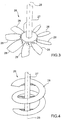
- the reactor 2 furthermore includes a mixer 26, which is suitable for mixing the plastic material and the catalyst and, in turn, comprises a shaft 27 and one or more mixing elements 28 connected integrally to the shaft 27.
- the shaft 27 is suitable for rotating around its own longitudinal axis 29 which, advantageously, extends in a substantially vertical direction.
- the shaft 27 is driven, during use, by a motor 30 (brushless) positioned on the upper wall 20.
- the mixing element 28 is so shaped that, during depolymerisation, the plastic material is lifted upwards and then drops back down again.
- the mixing element 28 is shaped so that, during depolymerisation, it pushes at least part of the plastic material away from said longitudinal axis 29.
- the mixing element 28 is shaped so that, during depolymerisation, it pushes at least part of the plastic material towards said longitudinal axis 29.
- the mixing elements 28 comprise, in particular are, a plurality of slanting blades.
- the mixing elements 28 comprise, in particular are, a plurality of (in particular two) slanting blades.
- the inclination of the blades is lesser at the level of the shaft 27 and greater at an end 28a opposite to the shaft 27.
- the mixing elements 28 are shaped so that the plastic material is lifted upwards when positioned at the level of the lateral wall 18 and drops back down again once it is positioned at the level of the shaft 27.
- the mixing element 28 has a helical shape.
- the mixing element 28 has a helical shape.
- the mixing element 28 has, at its lateral ends, substantially vertical walls 28'.
- the mixing elements 28 comprise a plurality of slanting blades and tabs 31, which project substantially vertically from the blades.
- the tabs 31 are shaped so as to push at least part of the plastic material away from said axis 29.
- the mixing elements 28 comprise a plurality of slanting blades and protrusions 32.
- the protrusions 32 are shaped so as to push at least part of the plastic material towards the axis 29.
- the mixing element 28 comprises, in particular is, a simple auger.
- the mixing element 28 comprises, in particular is, a multi-turn auger.
- the mixing elements 28 of the embodiments shown in figures 4 and 6-8 are shaped so as to push the plastic material upwards; the latter tends to drop back down in the areas of the reaction chamber 21 where the mixing elements 28 are not present.
- the reactor 2 furthermore includes a heating device 33 to supply heat to the plastic material during depolymerisation by means of electricity.
- heating of the plastic material by means of electricity and not using the combustion of hydrocarbons in furnaces permits significant reduction in the emission of gases that are harmful to the environment.
- reaction chamber 21 is substantially isolated from the external environment.
- the reaction chamber 21 is provided only with the inlet and outlet apertures 22 and 23 which connect the reaction chamber 21 itself only to the feed unit 3 and the outlet unit 4. Due to the fact that the reaction chamber 21 is substantially isolated from the external environment, the relatively low-boiling compounds released during the depolymerisation are not emitted directly into the environment.
- the heating device 33 comprises at least one heating element 34; advantageously, the heating element 34 comprises, in particular consists of, an electrical resistance.
- the heating element 34 is positioned around the reaction chamber 21, advantageously substantially in contact with the lateral and base walls 18 and/or 19.
- the heating element 34 is positioned inside the reaction chamber 21.
- the heating element 34 (an electrical resistance) is combined with the mixer 26, in particular it is positioned inside one of the mixing elements 28.
- the heating element 34 is powered by an electrical current passing through wires 34', which extend inside the shaft 27.
- the heating element 34 is positioned on an external surface of the mixing element 28.
- the heating device 33 comprises a plurality of heating elements 34, each of which is combined with a relative mixing element 28.
- the heating element 34 comprises a microwave resonator and/or an induction heater.
- the use of electricity to power the heating element 34 is advantageous also because it facilitates selection of the point or points in which the heat is transferred to the material.
- the electrical power supply makes it relatively easy both to position and maintain movement of the heating element 34 inside the reaction chamber 21.
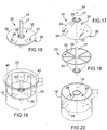
- the heating element 34 has a heating surface 35 delimited by a peripheral edge 36.
- the peripheral edge 36 extends along the lateral wall 18, in particular substantially in contact.
- the surface 35 is delimited by the lateral wall 18.
- the surface 35 has a plurality of holes 37 and/or slits 38 through which, during use, the plastic material and/or the relatively low-boiling compounds pass.
- the particular shape of the surface 35 also where not heated, limits expansion of the plastic material, reducing the production of foam and, therefore, limiting the risk of plastic material obstructing the outlet aperture 23 and/or reaching the condenser 24.
- the surface 35 is positioned immediately above and/or immediately below the level L.
- the surface 35 is substantially flat and extends crosswise to the axis 29 in a substantially horizontal manner.
- the heating element 34 is connected integrally to the shaft 27 by means of spokes 39; in this way, in use, the heating element 34 rotates about axis 29.
- the surface 35 has a substantially truncated cone shape with the vertex facing upwards ( figure 17 ) or downwards ( figure 18 ).
- the heating element 34 is connected integrally to the shaft 27 by means of the spokes 39; in this way, during use, the heating element 34 rotates around axis 29.
- the embodiment shown in figure 19 is substantially identical to the embodiment shown in figure 16 and differs from the latter only due to the fact that the heating element 34 is integrally connected by means of arms 40 to the upper wall 20 and not to the shaft 27; in this way, during use, the heating element 34 does not rotate around axis 29.
- the embodiment shown in figure 20 is substantially identical to the embodiment shown in figure 17 and differs from the latter only due to the fact that the heating element 34 is connected integrally by means of pins 41 to the lateral wall 18 and not to the shaft 27; in this way, during use, the heating element 34 does not rotate around axis 29.
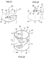
- the reactor 2 furthermore comprises a cleaning device 42 to keep the surfaces 35 clean.
- the cleaning device 42 comprises at least one scraper 43, which is designed for coming substantially into contact with the respective surface 35. During use, the scraper 43 and the surface 35 are moved with respect to each other so that the scraper 43 slides on the surface 35.
- the surface 35 is substantially flat and extends crosswise to the axis 29 in a substantially horizontal manner.
- the scraper 43 is integrally connected to the lateral wall 18 and is positioned in a substantially horizontal direction.
- the heating element 34 is integrally connected to the shaft 27 by means of the spokes 39; in this way, in use, the heating element 34 rotates around axis 29 and the surface 35 moves with respect to the scraper 43.
- the surface 35 has a substantially truncated cone shape with the vertex facing upwards.
- the scraper 43 is integrally connected to the lateral wall 18 and is positioned in an oblique direction.
- the heating element 34 is integrally connected to the shaft 27 by means of the spokes 39; in this way, in use, the heating element 34 rotates around the axis 29 and the surface 35 moves with respect to the scraper 43.
- the surfaces 35 are provided with holes and/or slits as shown in figures 16-20 .
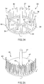
- the heating device 33 comprises a plurality of heating elements 34 arranged on a substantially circular frame 44 connected to the shaft 27 by means of spokes 45.
- the heating elements 34 have a substantially cylindrical shape with constant circular cross section. According to variations not shown, the heating elements 34 have a polygonal (in particular square) cross section.
- the frame 44 is positioned above the level L so that the heating elements 34 supply heat to the relatively low-boiling compounds present in this portion of the reaction chamber 21.
- the heating elements 34 are fixed to the upper wall 20.
- the heating device 33 comprises a heating element 34 (for example as shown in figure 5 ) positioned below the level L and a heating element 34 (for example as shown in figure 24 ) positioned above the level L.
- the heating element 34 positioned below the level L facilitates depolymerisation of the plastic material; the heating element 34 positioned above the level L facilitates outflow of the substantially low-boiling compounds via the aperture 23.
- the reactor 2 furthermore comprises a foam-reducing device 46 ( figure 25 ); the device 46 is suitable for limiting the risk of the plastic material obstructing the outlet aperture 23 and/or reaching the condenser 24.
- Device 46 (advantageously positioned below the level L) comprises a wheel 47 integrally connected to the shaft 27 by means of spokes 48, and a plurality of elements 49 for cavitation (in figure 25 only some elements 49 are shown).
- Each element 49 has a substantially vertical longitudinal extension and a V-shaped cross section.
- each element 49 is moved crosswise, in particular substantially horizontally. In this way cavitation is obtained at the rear of each element 49 which favours aggregation and elimination of the relatively low-boiling compounds.
- the cross section vertex of the element 49 is in an anterior position with respect to the direction of forward movement.
- the outlet unit 4 comprises an intermediate tank 50 positioned downstream of the condenser 24 to collect the relatively low-boiling compounds coming from the condenser 24 itself.
- substantially non-condensable gases separate from the relatively low-boiling compounds and reach a tank 51, passing through a duct 52.
- the relatively low-boiling compounds are conveyed by a system of ducts 53 to two tanks 54, at the level of which further substantially non-condensable gases can be released.
- the substantially non-condensable compounds present inside the tank 50 or coming from the tanks 54 through a duct 55 are fed to a electricity-generating assembly 56 comprising a four-stroke Otto-cycle engine which burns the substantially non-condensable gases; the engine has a high operating temperature, in particular above 1500°C.
- the electricity produced by the electricity-generating assembly 56 is usually used by the plant 1.
- the relatively low-boiling compounds present in the tanks 54 are fed through a system of ducts 57 to two electricity-generating assemblies 58, each of which comprises a respective diesel engine and is designed for producing electricity by combusting the relatively low-boiling compounds.
- the electricity-generating assemblies 58 are connected to electricity grid 59 so as to feed the excess energy produced with respect to consumption of the plant 1 into said electricity grid 59. It is important to point out that part of the energy produced by the generating sets 56 and 58 of the plant 1 is used to power the heating device 33.
- the emission of combustion gases that are potentially harmful for the environment is drastically reduced with respect to the systems described in the state of the art. In particular, an emission of NO x below 250mg/Nmc at 5% of O 2 and an emission of CO below 3250mg/Nmc at 5% of O 2 are obtained.
- the reactor 2 comprises a lateral wall 18, a bottom wall 19 and an upper wall 20; a reaction chamber 21, inside which at least part of the plastic material is at least partially depolymerised and which is delimited at least partially by the lateral, bottom and upper walls 18, 19, 20; the surface 35 for limiting expansion of the material is delimited by the lateral wall 18.
- the reactor includes a mixer 26, which in turn comprises a shaft 27 rotating about its own longitudinal axis 29 and at least one mixing element 28 connected integral with the shaft 27.
- the mixing element 28 is shaped so that, during the depolymerisation step, the plastic material is lifted upwards and then drops back down again.
- the mixing element 28 comprises a blade.
- the mixing element 28 has a substantially helical shape.
- the mixing element 28 is shaped so that, during the depolymerisation step, it pushes at least part of the plastic material away from said longitudinal axis 29.
- the mixing element 28 is shaped so that, during the depolymerisation step, it pushes at least part of the plastic material towards said longitudinal axis 29.
- the first heating element 34 is supported by the mixing element 28.
- the reaction chamber 21 has an aperture 23 shaped so as to facilitate outflow of the relatively low-boiling compounds; in particular, the aperture 23 is funnel-shaped.
- the production rate of a method in which the reactor 2 is heated externally was compared with the production rate of a method in which the same reactor 2 was heated internally.
- the test was conducted by placing inside the reactor 2 (capacity 40 litres) 30 litres of plastic with the catalyst.
- the reactor had two internal heating elements 34, one fixed and one moving combined with a mixing element 28; each heating element 34 was provided with an electrical resistance.
- the test was conducted maintaining the working conditions equal in both cases. In the first case the internal heating elements 34 were kept switched off, bringing the plastic to a temperature of 420°C by means of the external heating; an hourly production rate of approximately 2 litres of paraffinic product was achieved. In the second case, the internal heating elements 34 were switched on, recording an increase in the production of paraffinic product of 45%.
Landscapes
- Chemical & Material Sciences (AREA)
- Chemical Kinetics & Catalysis (AREA)
- Organic Chemistry (AREA)
- Engineering & Computer Science (AREA)
- Oil, Petroleum & Natural Gas (AREA)
- Life Sciences & Earth Sciences (AREA)
- Wood Science & Technology (AREA)
- General Chemical & Material Sciences (AREA)
- Mechanical Engineering (AREA)
- Polymers & Plastics (AREA)
- Medicinal Chemistry (AREA)
- Health & Medical Sciences (AREA)
- Sustainable Development (AREA)
- Aviation & Aerospace Engineering (AREA)
- Physical Or Chemical Processes And Apparatus (AREA)
- Separation, Recovery Or Treatment Of Waste Materials Containing Plastics (AREA)
Claims (15)
- Verfahren zur thermokatalytischen Depolymerisation von Kunststoffmaterial, wobei das Verfahren aufweist:einen Schritt, in dem das Kunststoffmaterial und ein Katalysator zur Depolymerisation in einen Reaktor (2), der zumindest eine Heizeinrichtung (33) aufweist, eingebracht werden;einen Depolymerisationsschritt, in dem die Heizeinrichtung (33) dem Kunststoffmaterial Wärme zuführt und wobei zumindest ein Teil des Kunststoffmaterials zumindest teilweise depolymerisiert wird, um vergleichsweise niedrigsiedende Stoffe zu erhalten; undeinen Auslassschritt, in dem zumindest ein Teil der vergleichsweise niedrigsiedenden Stoffe den Reaktor (2) verlassen; wobeider Reaktor (2) zumindest eine Außenwand (18; 19; 20) und ein Reaktionskammer (21) aufweist, die zumindest teilweise von der Außenwand (18; 19; 20) begrenzt wird und in der sich während des Depolymerisationsschritts das Kunststoffmaterial und der Katalysator befinden; unddas Verfahren dadurch gekennzeichnet ist, dass die Heizeinrichtung (33) zumindest ein erstes Heizelement (34; 34a), angeordnet in der Reaktionskammer (21), aufweist; das erste Heizelement (34, 34a) während des Depolymerisationsschritts in Bewegung gehalten wird, um dessen Position in der Reaktionskammer (21) zu verändern; das Verfahren ferner einen Elektrizitätserzeugungsschritt aufweist, der dem Auslassschritt nachfolgt und in dem zumindest ein Teil der vergleichsweise niedrigsiedenden Stoffe, die den Reaktor (2) verlassen haben, für die Erzeugung von Elektrizität verbrannt werden; und die erzeugte Elektrizität zumindest teilweise von der Heizeinrichtung (33) zum Erwärmen des Kunststoffmaterials verwendet wird.
- Verfahren nach Anspruch 1, das einen Trennungsschritt aufweist, in dem im Wesentlichen nicht kondensierbare Gase von den im Wesentlichen niedrigsiedenden Stoffen getrennt werden, wobei während des Elektrizitätserzeugungsschritts die im Wesentlichen nicht kondensierbaren Gase zumindest teilweise verbrannt werden.
- Verfahren nach Anspruch 2, bei dem während des Elektrizitätserzeugungsschritts ein Ottomotor die im Wesentlichen nicht kondensierbaren Gase verbrennt.
- Verfahren nach einem der vorigen Ansprüche, bei dem während des Elektrizitätserzeugungsschritts ein Dieselmotor die vergleichsweise niedrigsiedenden Stoffe verbrennt.
- Verfahren nach einem der vorigen Ansprüche, bei dem während des Depolymerisationsschritts das Kunststoffmaterial unterhalb eines bestimmten Niveaus (L) gehalten wird, das erste Heizelement (34; 34a) unterhalb des bestimmten Niveaus (L) positioniert wird; wobei die Heizeinrichtung (33) zumindest ein zweites Heizelement (34; 34b) aufweist, das oberhalb des bestimmten Niveaus (L) positioniert wird, um die vergleichsweise niedrigsiedenden Stoffe, positioniert oberhalb des bestimmten Niveaus (L), zu erhitzen.
- Verfahren nach Anspruch 5, bei dem das zweite Heizelement (34; 34b) eine zweite Heizfläche (35) aufweist; der Reaktor (2) eine Reinigungseinrichtung (42) aufweist, die wiederum einen zweiten Schaber (43) aufweist, der mit der zweiten Heizfläche (35) gekoppelt ist; wobei während des Depolymerisationsschritts die zweite Heizfläche (35) und der zweite Schaber (43) relativ zueinander bewegt werden.
- Verfahren nach einem der vorigen Ansprüche, bei dem das erste Heizelement (34; 34a) eine erste Heizfläche (35) aufweist; der Reaktor (2) eine Reinigungseinrichtung (42) aufweist, die wiederum einen ersten Schaber (43) aufweist, der mit der ersten Heizfläche (35) gekoppelt ist; wobei während des Depolymerisationsschritts die erste Heizfläche (35) und der erste Schaber (43) relativ zueinander bewegt werden.
- Verfahren nach Anspruch 7, bei dem der Reaktor (2) eine Drehwelle (27) aufweist, die mit dem ersten Schaber (43) oder der ersten Heizfläche (35) verbunden ist und den ersten Schaber (43) oder die erste Heizfläche (35) um die eigene Längsachse (29) dreht.
- Verfahren nach einem der vorigen Ansprüche, bei dem eine Schaumreduktionseinrichtung (46) vorgesehen ist; und die Schaumreduktionseinrichtung (46) zumindest ein Element (49) zur Kavitation aufweist, das in dem Kunststoffmaterial bewegt wird, um Kavitation zu erhalten, welche Aggregation und Elimination der vergleichsweise niedrigsiedenden Komponenten begünstigt.
- Verfahren nach Anspruch 9, bei dem das Element (49) zur Kavitation vertikal im Wesentlichen länglich ausgebildet ist und quer, insbesondere im Wesentlichen horizontal, bewegt wird.
- Verfahren nach Anspruch 9 oder 10, bei dem das Element (49) zur Kavitation einen V-förmigen Querschnitt aufweist.
- Verfahren nach einem der vorigen Ansprüche, bei dem eine Schaumreduktionseinrichtung vorgesehen ist; und die Schaumreduktionseinrichtung eine Fläche (35) zum Begrenzen einer Ausdehnung des Materials aufweist, die zumindest eine Öffnung (37; 38) aufweist, durch welche die vergleichsweise niedrigsiedenden Stoffe treten.
- Verfahren nach einem der vorigen Ansprüche, bei dem die Heizeinrichtung (33) zumindest einen elektrischen Widerstand (34) aufweist.
- Verfahren nach einem der vorigen Ansprüche, bei dem der Reaktor (2) einen Mischer (26) aufweist, der während des Depolymerisationsschritts das Kunststoffmaterial in Bewegung hält; wobei das erste Heizelement (34; 34a) mit dem Mischer (26) kombiniert ist.
- Verfahren nach einem der vorigen Ansprüche, bei dem die Heizeinrichtung (33) zumindest ein zweites Heizelement (34; 34b) aufweist, wobei das zweite Element fest angebracht ist.
Applications Claiming Priority (1)
| Application Number | Priority Date | Filing Date | Title |
|---|---|---|---|
| PCT/IT2007/000832 WO2009069161A1 (en) | 2007-11-29 | 2007-11-29 | Method for the thermocatalytic depolymerisation of plastic material |
Publications (2)
| Publication Number | Publication Date |
|---|---|
| EP2242570A1 EP2242570A1 (de) | 2010-10-27 |
| EP2242570B1 true EP2242570B1 (de) | 2018-02-14 |
Family
ID=39643845
Family Applications (1)
| Application Number | Title | Priority Date | Filing Date |
|---|---|---|---|
| EP07866775.5A Active EP2242570B1 (de) | 2007-11-29 | 2007-11-29 | Verfahren zur thermokatalytischen depolymerisation von kunststoffmaterial |
Country Status (2)
| Country | Link |
|---|---|
| EP (1) | EP2242570B1 (de) |
| WO (1) | WO2009069161A1 (de) |
Cited By (2)
| Publication number | Priority date | Publication date | Assignee | Title |
|---|---|---|---|---|
| IT202100028121A1 (it) | 2021-11-04 | 2023-05-04 | Lifenergy Italia S R L | Impianto e processo di depolimerizzazione termo-catalitica di materie plastiche poliolefiniche per la produzione di idrocarburi |
| WO2025218842A1 (en) * | 2024-04-18 | 2025-10-23 | Lebedev Igor | Pre-processing reactor for a recycled polymeric feedstock processing device and a device comprising said reactor |
Families Citing this family (21)
| Publication number | Priority date | Publication date | Assignee | Title |
|---|---|---|---|---|
| EP2269491A1 (de) * | 2009-06-30 | 2011-01-05 | Braun GmbH | Rührwerkzeug für schwere Teige |
| PL2448455T3 (pl) * | 2009-06-30 | 2015-04-30 | Delonghi Braun Household Gmbh | Narzędzie do mieszania gęstego ciasta |
| EP2941319B1 (de) * | 2013-01-07 | 2022-08-17 | 1,4 Group, Inc. | Wärmevernebler zur erzeugung stabiler aerosole |
| WO2014177727A1 (es) * | 2013-04-30 | 2014-11-06 | Aragonesa De Reciclados Plásticos, S.A. | Reactor despolimerizador en continuo |
| SG2013081963A (en) * | 2013-06-04 | 2015-12-30 | Enviro Power Pte Ltd | System and method for converting plastic/rubber to hydrocarbon fuel by thermo-catalytic process |
| PL404773A1 (pl) * | 2013-07-18 | 2015-01-19 | Ajh047 Spółka Z Ograniczoną Odpowiedzialnością | Sposób nanoszenia mikrocząstek metalu na materiał polimerowy, urządzenie do realizacji sposobu, materiał polimerowy z mikrocząsteczkami metalu oraz zastosowanie materiału polimerowego |
| KR101620177B1 (ko) * | 2013-07-18 | 2016-05-12 | 주식회사 엘지화학 | 기액 분리 장치 |
| CN103933889B (zh) * | 2013-11-25 | 2016-01-13 | 大连隆星新材料有限公司 | 石蜡生产搅拌设备用搅拌桨 |
| CN104645857B (zh) * | 2013-11-25 | 2017-12-05 | 大连隆星新材料有限公司 | 石蜡搅拌装置 |
| CN103770231B (zh) * | 2014-01-27 | 2016-04-13 | 华南理工大学 | 一种双向拉伸形变协同作用的混合方法及装置 |
| CN104190346B (zh) * | 2014-08-18 | 2016-03-02 | 华南理工大学 | 一种等离子体电解氧化陶瓷膜催化转酯化反应搅拌装置 |
| JP6927510B2 (ja) * | 2016-07-08 | 2021-09-01 | 学校法人金井学園 | 加熱撹拌装置 |
| CN106512483B (zh) * | 2016-10-31 | 2018-10-09 | 北京金风科创风电设备有限公司 | 液体脱挥器及其搅拌器 |
| CN108211964A (zh) * | 2017-12-29 | 2018-06-29 | 南阳英良石业有限公司 | 一种人造石制备用的原料混合装置 |
| JP7076091B2 (ja) * | 2018-01-04 | 2022-05-27 | 関西電力株式会社 | 加熱冷却撹拌装置 |
| FR3081732B1 (fr) * | 2018-05-29 | 2020-09-11 | Deasyl Sa | Broyeur tridimensionnel, son procede de mise en œuvre et ses utilisations |
| CN108673775A (zh) * | 2018-06-29 | 2018-10-19 | 德清意欣塑料制品有限公司 | 破碎塑料搅拌机构 |
| CN108889183A (zh) * | 2018-07-13 | 2018-11-27 | 安徽康瑞高科新材料技术工程有限公司 | 一种涂料储藏罐 |
| IT202000008245A1 (it) * | 2020-04-17 | 2021-10-17 | B4Chem S R L | Reattore chimico |
| CZ34946U1 (cs) * | 2021-02-10 | 2021-03-23 | THEODOR DESIGN, s.r.o. | Zařízení pro termický rozklad materiálů bez přístupu kyslíku |
| JP2023180932A (ja) * | 2022-06-10 | 2023-12-21 | 国立大学法人大阪大学 | 加熱撹拌装置、加熱方法 |
Family Cites Families (9)
| Publication number | Priority date | Publication date | Assignee | Title |
|---|---|---|---|---|
| CA1080147A (en) * | 1975-03-14 | 1980-06-24 | Ren W. Chambers | Obtaining hydrocarbons from rubber tires and waste plastic materials |
| US4584421A (en) * | 1983-03-25 | 1986-04-22 | Agency Of Industrial Science And Technology | Method for thermal decomposition of plastic scraps and apparatus for disposal of plastic scraps |
| DE3743051A1 (de) * | 1987-12-18 | 1989-06-29 | Davy Mckee Ag | Vorrichtung zur behandlung von hochviskosen substanzen |
| FI944244A0 (fi) * | 1994-09-13 | 1994-09-13 | Waertsilae Nsd Oy Ab | Foerfarande foer framstaellning av dieselmotorbraensle av bildaeck och liknande avfallsgummimaterial |
| FR2775621B1 (fr) * | 1998-03-03 | 2000-04-07 | Etia Evaluation Technologique | Dispositif melangeur et de traitement thermique de produits solides ou liquides |
| PL188936B1 (pl) * | 1999-04-26 | 2005-05-31 | Zmuda Henryk | Sposób przekształcania odpadów poliolefinowych w węglowodory oraz instalacja do realizacji tego sposobu |
| FR2841154B1 (fr) * | 2002-06-19 | 2005-03-25 | Electricite De France | Agitateur rotatif a surface chauffante pour milieu liquide, pulverulent ou pateux |
| MXPA06010339A (es) * | 2004-03-14 | 2007-01-23 | Ozmotech Pty Ltd | Planta y proceso para la conversion de material de desperdicio en combustible liquido. |
| EP1946829A1 (de) * | 2007-01-05 | 2008-07-23 | Sterecycle Ltd. | Prozess und Vorrichtung zur Abfallbehandlung |
-
2007
- 2007-11-29 EP EP07866775.5A patent/EP2242570B1/de active Active
- 2007-11-29 WO PCT/IT2007/000832 patent/WO2009069161A1/en not_active Ceased
Cited By (2)
| Publication number | Priority date | Publication date | Assignee | Title |
|---|---|---|---|---|
| IT202100028121A1 (it) | 2021-11-04 | 2023-05-04 | Lifenergy Italia S R L | Impianto e processo di depolimerizzazione termo-catalitica di materie plastiche poliolefiniche per la produzione di idrocarburi |
| WO2025218842A1 (en) * | 2024-04-18 | 2025-10-23 | Lebedev Igor | Pre-processing reactor for a recycled polymeric feedstock processing device and a device comprising said reactor |
Also Published As
| Publication number | Publication date |
|---|---|
| EP2242570A1 (de) | 2010-10-27 |
| WO2009069161A1 (en) | 2009-06-04 |
Similar Documents
| Publication | Publication Date | Title |
|---|---|---|
| EP2242570B1 (de) | Verfahren zur thermokatalytischen depolymerisation von kunststoffmaterial | |
| KR101229655B1 (ko) | 음식물 처리기의 건조로 | |
| KR101070437B1 (ko) | 중앙 집중형 슬러지 건조장치 | |
| CN103245182B (zh) | 间接加热式干燥装置 | |
| EP2233547A1 (de) | Procédé et réacteur chimique pour la production d'hydrocarbures gazeux dérivés de matériaux en plastique | |
| WO2007138965A1 (ja) | 油化装置 | |
| KR20200041557A (ko) | 폐식용유 회수가 가능한 튀김부스러기 기반 펠릿 제조장치 및 그 방법 | |
| KR101661282B1 (ko) | 축분 건조 장치 | |
| KR20230013446A (ko) | 슬러지 건조 장치 | |
| WO2021131026A1 (ja) | 廃棄物処理装置 | |
| EP2805932A1 (de) | Organischer Abfallkomposter und Verfahren zur Kompostierung von organischen Abfällen | |
| CN112408742A (zh) | 一种污泥烘干机 | |
| JP2012144609A (ja) | 廃プラスチックの接触分解炉および廃プラスチック連続油化装置 | |
| KR101977012B1 (ko) | 축인분을 이용한 유기질 복합 비료제조장치 | |
| EP2393875B1 (de) | Verfahren zur thermokatalytischen depolymerisation von kunststoffabfällen, system zur thermokatalytischen depolymerisation von kunststoffabfällen und reaktor zur thermokatalytischen depolymerisation von kunststoffabfällen | |
| KR20200012232A (ko) | 슬러지 건조 장치 | |
| JP2005537368A (ja) | 汚泥および炭質の変換 | |
| JP2010243032A (ja) | 乾燥装置 | |
| KR100887622B1 (ko) | 하수고도처리장의 슬러지 건조장치 | |
| CN105819651A (zh) | 底部进风的污泥干化装置 | |
| KR101667359B1 (ko) | 폐 수지제품 고형 연료의 제조 장치 및 방법 | |
| JP2013047592A (ja) | 攪拌乾燥装置 | |
| KR20100024837A (ko) | 다수의 회전날개가 구비된 교반스크류 및 상기 교반스크류를 갖는 음식물 처리기의 건조로 | |
| KR0153704B1 (ko) | 음식물찌꺼기 퇴비화 처리장치 | |
| CN206870432U (zh) | 一种肉类蛋白榨油系统 |
Legal Events
| Date | Code | Title | Description |
|---|---|---|---|
| PUAI | Public reference made under article 153(3) epc to a published international application that has entered the european phase |
Free format text: ORIGINAL CODE: 0009012 |
|
| 17P | Request for examination filed |
Effective date: 20100629 |
|
| AK | Designated contracting states |
Kind code of ref document: A1 Designated state(s): AT BE BG CH CY CZ DE DK EE ES FI FR GB GR HU IE IS IT LI LT LU LV MC MT NL PL PT RO SE SI SK TR |
|
| AX | Request for extension of the european patent |
Extension state: AL BA HR MK RS |
|
| DAX | Request for extension of the european patent (deleted) | ||
| RAP1 | Party data changed (applicant data changed or rights of an application transferred) |
Owner name: ENERGY & ECOLOGY S.R.L. |
|
| GRAP | Despatch of communication of intention to grant a patent |
Free format text: ORIGINAL CODE: EPIDOSNIGR1 |
|
| INTG | Intention to grant announced |
Effective date: 20170831 |
|
| GRAS | Grant fee paid |
Free format text: ORIGINAL CODE: EPIDOSNIGR3 |
|
| GRAA | (expected) grant |
Free format text: ORIGINAL CODE: 0009210 |
|
| AK | Designated contracting states |
Kind code of ref document: B1 Designated state(s): AT BE BG CH CY CZ DE DK EE ES FI FR GB GR HU IE IS IT LI LT LU LV MC MT NL PL PT RO SE SI SK TR |
|
| REG | Reference to a national code |
Ref country code: GB Ref legal event code: FG4D |
|
| REG | Reference to a national code |
Ref country code: CH Ref legal event code: EP |
|
| REG | Reference to a national code |
Ref country code: IE Ref legal event code: FG4D |
|
| REG | Reference to a national code |
Ref country code: DE Ref legal event code: R096 Ref document number: 602007053931 Country of ref document: DE Ref country code: AT Ref legal event code: REF Ref document number: 969525 Country of ref document: AT Kind code of ref document: T Effective date: 20180315 |
|
| REG | Reference to a national code |
Ref country code: NL Ref legal event code: MP Effective date: 20180214 |
|
| REG | Reference to a national code |
Ref country code: AT Ref legal event code: MK05 Ref document number: 969525 Country of ref document: AT Kind code of ref document: T Effective date: 20180214 |
|
| PG25 | Lapsed in a contracting state [announced via postgrant information from national office to epo] |
Ref country code: FI Free format text: LAPSE BECAUSE OF FAILURE TO SUBMIT A TRANSLATION OF THE DESCRIPTION OR TO PAY THE FEE WITHIN THE PRESCRIBED TIME-LIMIT Effective date: 20180214 Ref country code: LT Free format text: LAPSE BECAUSE OF FAILURE TO SUBMIT A TRANSLATION OF THE DESCRIPTION OR TO PAY THE FEE WITHIN THE PRESCRIBED TIME-LIMIT Effective date: 20180214 Ref country code: ES Free format text: LAPSE BECAUSE OF FAILURE TO SUBMIT A TRANSLATION OF THE DESCRIPTION OR TO PAY THE FEE WITHIN THE PRESCRIBED TIME-LIMIT Effective date: 20180214 Ref country code: NL Free format text: LAPSE BECAUSE OF FAILURE TO SUBMIT A TRANSLATION OF THE DESCRIPTION OR TO PAY THE FEE WITHIN THE PRESCRIBED TIME-LIMIT Effective date: 20180214 Ref country code: CY Free format text: LAPSE BECAUSE OF FAILURE TO SUBMIT A TRANSLATION OF THE DESCRIPTION OR TO PAY THE FEE WITHIN THE PRESCRIBED TIME-LIMIT Effective date: 20180214 |
|
| PG25 | Lapsed in a contracting state [announced via postgrant information from national office to epo] |
Ref country code: BG Free format text: LAPSE BECAUSE OF FAILURE TO SUBMIT A TRANSLATION OF THE DESCRIPTION OR TO PAY THE FEE WITHIN THE PRESCRIBED TIME-LIMIT Effective date: 20180514 Ref country code: GR Free format text: LAPSE BECAUSE OF FAILURE TO SUBMIT A TRANSLATION OF THE DESCRIPTION OR TO PAY THE FEE WITHIN THE PRESCRIBED TIME-LIMIT Effective date: 20180515 Ref country code: SE Free format text: LAPSE BECAUSE OF FAILURE TO SUBMIT A TRANSLATION OF THE DESCRIPTION OR TO PAY THE FEE WITHIN THE PRESCRIBED TIME-LIMIT Effective date: 20180214 Ref country code: LV Free format text: LAPSE BECAUSE OF FAILURE TO SUBMIT A TRANSLATION OF THE DESCRIPTION OR TO PAY THE FEE WITHIN THE PRESCRIBED TIME-LIMIT Effective date: 20180214 Ref country code: AT Free format text: LAPSE BECAUSE OF FAILURE TO SUBMIT A TRANSLATION OF THE DESCRIPTION OR TO PAY THE FEE WITHIN THE PRESCRIBED TIME-LIMIT Effective date: 20180214 |
|
| PG25 | Lapsed in a contracting state [announced via postgrant information from national office to epo] |
Ref country code: PL Free format text: LAPSE BECAUSE OF FAILURE TO SUBMIT A TRANSLATION OF THE DESCRIPTION OR TO PAY THE FEE WITHIN THE PRESCRIBED TIME-LIMIT Effective date: 20180214 Ref country code: EE Free format text: LAPSE BECAUSE OF FAILURE TO SUBMIT A TRANSLATION OF THE DESCRIPTION OR TO PAY THE FEE WITHIN THE PRESCRIBED TIME-LIMIT Effective date: 20180214 Ref country code: RO Free format text: LAPSE BECAUSE OF FAILURE TO SUBMIT A TRANSLATION OF THE DESCRIPTION OR TO PAY THE FEE WITHIN THE PRESCRIBED TIME-LIMIT Effective date: 20180214 |
|
| REG | Reference to a national code |
Ref country code: DE Ref legal event code: R097 Ref document number: 602007053931 Country of ref document: DE |
|
| PG25 | Lapsed in a contracting state [announced via postgrant information from national office to epo] |
Ref country code: CZ Free format text: LAPSE BECAUSE OF FAILURE TO SUBMIT A TRANSLATION OF THE DESCRIPTION OR TO PAY THE FEE WITHIN THE PRESCRIBED TIME-LIMIT Effective date: 20180214 Ref country code: SK Free format text: LAPSE BECAUSE OF FAILURE TO SUBMIT A TRANSLATION OF THE DESCRIPTION OR TO PAY THE FEE WITHIN THE PRESCRIBED TIME-LIMIT Effective date: 20180214 Ref country code: DK Free format text: LAPSE BECAUSE OF FAILURE TO SUBMIT A TRANSLATION OF THE DESCRIPTION OR TO PAY THE FEE WITHIN THE PRESCRIBED TIME-LIMIT Effective date: 20180214 |
|
| PLBE | No opposition filed within time limit |
Free format text: ORIGINAL CODE: 0009261 |
|
| STAA | Information on the status of an ep patent application or granted ep patent |
Free format text: STATUS: NO OPPOSITION FILED WITHIN TIME LIMIT |
|
| 26N | No opposition filed |
Effective date: 20181115 |
|
| PG25 | Lapsed in a contracting state [announced via postgrant information from national office to epo] |
Ref country code: SI Free format text: LAPSE BECAUSE OF FAILURE TO SUBMIT A TRANSLATION OF THE DESCRIPTION OR TO PAY THE FEE WITHIN THE PRESCRIBED TIME-LIMIT Effective date: 20180214 |
|
| REG | Reference to a national code |
Ref country code: DE Ref legal event code: R119 Ref document number: 602007053931 Country of ref document: DE |
|
| REG | Reference to a national code |
Ref country code: CH Ref legal event code: PL |
|
| GBPC | Gb: european patent ceased through non-payment of renewal fee |
Effective date: 20181129 |
|
| PG25 | Lapsed in a contracting state [announced via postgrant information from national office to epo] |
Ref country code: LU Free format text: LAPSE BECAUSE OF NON-PAYMENT OF DUE FEES Effective date: 20181129 Ref country code: MC Free format text: LAPSE BECAUSE OF FAILURE TO SUBMIT A TRANSLATION OF THE DESCRIPTION OR TO PAY THE FEE WITHIN THE PRESCRIBED TIME-LIMIT Effective date: 20180214 |
|
| REG | Reference to a national code |
Ref country code: BE Ref legal event code: MM Effective date: 20181130 |
|
| REG | Reference to a national code |
Ref country code: IE Ref legal event code: MM4A |
|
| PG25 | Lapsed in a contracting state [announced via postgrant information from national office to epo] |
Ref country code: LI Free format text: LAPSE BECAUSE OF NON-PAYMENT OF DUE FEES Effective date: 20181130 Ref country code: CH Free format text: LAPSE BECAUSE OF NON-PAYMENT OF DUE FEES Effective date: 20181130 |
|
| PG25 | Lapsed in a contracting state [announced via postgrant information from national office to epo] |
Ref country code: DE Free format text: LAPSE BECAUSE OF NON-PAYMENT OF DUE FEES Effective date: 20190601 Ref country code: FR Free format text: LAPSE BECAUSE OF NON-PAYMENT OF DUE FEES Effective date: 20181130 Ref country code: IE Free format text: LAPSE BECAUSE OF NON-PAYMENT OF DUE FEES Effective date: 20181129 |
|
| PG25 | Lapsed in a contracting state [announced via postgrant information from national office to epo] |
Ref country code: BE Free format text: LAPSE BECAUSE OF NON-PAYMENT OF DUE FEES Effective date: 20181130 |
|
| PG25 | Lapsed in a contracting state [announced via postgrant information from national office to epo] |
Ref country code: GB Free format text: LAPSE BECAUSE OF NON-PAYMENT OF DUE FEES Effective date: 20181129 |
|
| PG25 | Lapsed in a contracting state [announced via postgrant information from national office to epo] |
Ref country code: MT Free format text: LAPSE BECAUSE OF NON-PAYMENT OF DUE FEES Effective date: 20181129 |
|
| PG25 | Lapsed in a contracting state [announced via postgrant information from national office to epo] |
Ref country code: TR Free format text: LAPSE BECAUSE OF FAILURE TO SUBMIT A TRANSLATION OF THE DESCRIPTION OR TO PAY THE FEE WITHIN THE PRESCRIBED TIME-LIMIT Effective date: 20180214 |
|
| PG25 | Lapsed in a contracting state [announced via postgrant information from national office to epo] |
Ref country code: PT Free format text: LAPSE BECAUSE OF FAILURE TO SUBMIT A TRANSLATION OF THE DESCRIPTION OR TO PAY THE FEE WITHIN THE PRESCRIBED TIME-LIMIT Effective date: 20180214 |
|
| PG25 | Lapsed in a contracting state [announced via postgrant information from national office to epo] |
Ref country code: HU Free format text: LAPSE BECAUSE OF FAILURE TO SUBMIT A TRANSLATION OF THE DESCRIPTION OR TO PAY THE FEE WITHIN THE PRESCRIBED TIME-LIMIT; INVALID AB INITIO Effective date: 20071129 |
|
| PG25 | Lapsed in a contracting state [announced via postgrant information from national office to epo] |
Ref country code: IS Free format text: LAPSE BECAUSE OF FAILURE TO SUBMIT A TRANSLATION OF THE DESCRIPTION OR TO PAY THE FEE WITHIN THE PRESCRIBED TIME-LIMIT Effective date: 20180614 |
|
| PGFP | Annual fee paid to national office [announced via postgrant information from national office to epo] |
Ref country code: IT Payment date: 20251103 Year of fee payment: 19 |